 |
 |
 |
| Главная Журналы Популярное Audi - почему их так назвали? Как появилась марка Bmw? Откуда появился Lexus? Достижения и устремления Mercedes-Benz Первые модели Chevrolet Электромобиль Nissan Leaf |
Главная » Журналы » Simple coaxial reflectometer 1 ... 20 21 22 23 24 25 26 ... 80 This circuit is of the self-adjusting type and gives less distortion for a given degree of modulation than the more common limiter circuits. R Rj 470K, Yl wqtt r3 100K, Кг watt R4, R5 -1 megohm, Й watt Rg-3-megohm potentiometer d-0.00025 mica (approx.) Cj-0.01-Aifd. paper Cj-0.01-p,fd. popet С4-0.01-Mfd. paper D Dj-6H6, 6AL5, 7A6, or diode sections af a 6S8-GT 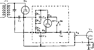 Figure 31 ALTERNATIVE NOISE LIMITER CIRCUIT cuit is useful in eliminating the grinding background noise that is the residual left by the diode clipper. In figure 33, the setting of the 470k potentiometer determines the operating level of the squelch action and should be set to eliminate the residual background noise. Because of the low inherent distortion of the TNS, it may be left in the circuit at all times. As with other limiters, the TNS requires a high signal level at the second detector for maximum limiting effect. 12-10 Special Considerations in U-H-F Receiver Design wavelength sections of parallel conductors or concentric transmission line are not only more efficient but also become of practical dimensions. Tuning Tubes and tuning capacitors con- Short Lines nected tothe open end of a transmission line provide a capacitance that makes the resonant length less than a quarter wave-length. The amount of shortening for a specified capacitive reactance is determined by the surge impedance of the line Transmission At increasingly higher frequen-Line Circuits cies, it becomes progressively more difficult to obtain a satisfactory amount of selectivity and impedance from an ordinary coil and capacitor used as a resonant circuit. On the other hand, quarter 2ND DET.-AUDIO 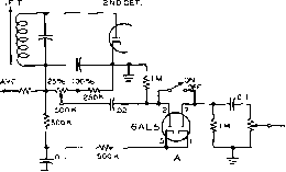 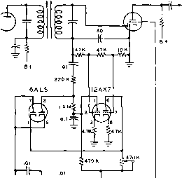 =L frrit-t-- 470 iou Figure 32 THE FULL-WAVE SERIES AUDIO NOISE LIMITER Figure 33 THE TNS AUDIO NOISE LIMITER 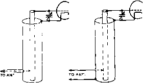 ® Figure 34 COUPLING AN ANTENNA TO A COAXIAL-RESONANT CIRCUIT (A) shows the recommended method for coup/in; i a coaxial line to a coax/of resonant circuit. (B shows an alternative method for use with an open-wire type of antenna feed line. ® ® О CONCENTRIC LINE CAVITT ELECTRON BEAM Figure 35 METHODS OF EXCITING A RESONANT CAVITY section nance: I. It is given by the equation for reso- 2 П-/С Z tan / in which 7T == 3-1416, / is the frequency, С the capacitance, the surge impedance of the line, and tan / is the tangent of the electrical length in degrees. The capacitive reactance of the capacitance across the end is 1/(27Т / С) ohms. For resonance, this must equal the surge impedance of the line times the tangent of its electrical length (in degrees, where 90° equals a quarter wave). It will be seen that twice the capacitance will resonate a line if its surge impedance is halved; also that a given capacitance has twice the loading effect when the frequency is doubled. Coupling Into Lines and Coaxial Circuits It is possible to couple into a parallel-rod line by tapping directly on one or both rods, preferably through blocking capacitors if any d.c. is present. More commonly, however, a hairpin is inductively coupled at the shorting bar end, either to the bar or to the two rods, or both. This normally will result in a balanced load. Should a loop unbalanced to ground be coupled in, any resulting unbalance reflected into the rods can be reduced with a simple Faraday screen, made of a few parallel wires placed between the haiфin loop and the rods. These should be soldered at only one end and grounded. An unbalanced tap on a coaxial resonant circuit can be made directly on the inner conductor at the point where it is properly matched (figure 34). For low impedances, such as a concentric line feeder, a small one-half turn loop can be inserted through a hole in the outer conductor of the coaxial circuit, being in effect a half of the hairpin type recommended for coupling balanced feeders to coaxial resonant lines. The size of the loop and closeness to the inner conductor determines the impedance matching and loading. Such loops coupled in near the shorting disc do not alter the tuning appreciably, if not overcoupled. Resonant A cavity is a closed resonant Cavities chamber made of metal. It is known also as a rhumbatron. The cavity, having both inductance and capacitance, supersedes coil-capacitor and capacitance-loaded transmission-line tuned circuits at extremely high frequencies where conventional L and С components, of even the most refined design, prove impractical because of the tiny electrical and physical dimensions they must have. Microwave cavities have high Q factors and are superior to conventional tuned circuits. They may be employed in the manner of an absoфtion wavemeter or as the tuned circuit in other r-f test instruments, and in microwave transmitters and receivers. Resonant cavities usually are closed on all sides and all of their walls are made of electrical conductor. However, in some forms, small openings are present for the purpose of excitation. Cavities have been produced in several shapes including the plain sphere. HANDBOOK U-H-F Circuits 233 TUNING CAVITY INPUT i OUTPU MOVEABLE DISC ->1 I CAVITY I OUTPUT ®  о о Figure 36 TUNING METHODS FOR CYLINDRICAL RESONANT CAVITIES Figure 37 THE BUTTERFLY RESONANT CIRCUIT Shown at (A) is the physical qppeorance of the butterfly circuit as used in fhe v-h-f artd lower u-h-f range. (B) shows an electrical representation of the circuit. dimpled sphere, sphere with reentrant cones of various sorts, cylinder, prism (including cube), ellipsoid, ellipsoid-hyperboloid, doughnut-shape, and various reentrant types. In appearance, they resemble in their simpler forms metal boxes or cans. The cavity actually is a linear circuit, but one which is superior to a conventional coaxial resonator in the s-h-f range. The cavity resonates in much the same manner as does a barrel or a closed room with reflecting walls. Because electromagnetic energy, and the associated electrostatic energy, oscillates to and fro inside them in one mode or another, resonant cavities resemble wave guides. The mode of operation in a cavity is affected by the manner in which micro-wave energy is injected. A cavity will resonate to a large number of frequencies, each being associated with a particular mode or standing-wave pattern. The lowest mode (lowest frequency of operation) of a cavity resonator normally is the one used. The resonant frequency of a cavity may be varied, if desired, by means of movable plungers or plugs, as shown in figure 36A, or a movable metal disc (see figure ЗбВ). A cavity that is too small for a given wavelength will not oscillate. The resonant frequencies of simple spherical, cylindrical, and cubical cavities may be calculated simply for one particular mode. Wavelength and cavity dimensions (in centimeters) are related by the following simple resonance formulae: For Cylinder Л, = 2.6 x radius Cube Л, = 2.83 X half of 1 side Sphere Aj = 2.28x radius Butterfly Unlike the cavity resonator, which Circuit in its conventional form is a device which can tune over a relatively narrow band, the butterfly circuit is a tunable resonator which permits coverage of a fairly wide u-h-f band. The butterfly circuit is very similar to a conventional coil-variable capacitor combination, except that both inductance and capacitance are provided by what appears to be a variable capacitor alone. The Q of this device is somewhat less than that of a concentric-line tuned circuit but is entirely adequate for numerous applications. Figure 37A shows construction of a single butterfly section. The butterfly-shaped rotor, from which the device derives its name, turns in relation to the unconventional stator. The two groups of stator fins or sectors are in effect joined together by a semi-circular metal band, integral with the sectors, which provides the circuit inductance. When the rotor is set to fill the loop opening (the position in which it is shown in figure 37A), the circuit inductance and capacitance are reduced to minimum. When the rotor occupies the position indicated by the dotted lines, the inductance and capacitance are at maximum. The tuning range of practical butterfly circuits is in the ratio of 1.5:1 to 3.5:1. Direct circuit connections may be made to points A and B. If balanced operation is desired, either point С or D will provide the electrical mid-point. Coupling may be effected by means of a small singleturn loop placed near point E or F. The butterfly thus permits continuous variation of both capacitance and inductance, as indicated by the equivalent circuit in figure 37B, while at the same time eliminating all pigtails and wiping contacts. Several butterfly sections may be stacked in parallel in the same way that variable capacitors are built up. In stacking these sections, the effectof adding inductances in parallel is to lower the total circuit inductance, while the addition of stators and rotors raises the total capacitance, as well as the ratio of maximum to minimum capacitance. Butterfly circuits have been applied specifically to oscillators for transmitters, superheterodyne receivers, and heterodyne frequency meters in the lOO-1000-Мс. frequency range. Receiver The types of resonant circuits de-Circuits scribed in the previous paragraphs have largely replaced conventional coil-capacitor circuits in the range above 100 Mc. Tuned short lines and butterfly circuits are used in the range from about 100 Mc. to perhaps 3500 Mc, and above about 3500 Mc. resonant cavities are used almost exclusively. The resonant cavity is also quite generally employed in the 2000-Mc. to 3500-Mc. range. In a properly designed receiver, thermal agitation in the first tuned circuit is amplified by subsequent tubes and predominates in the output. For good signal-to-set-noise ratio, therefore, one must strive for a high-gain low-noise r-f stage. Hiss can be held down by giving careful attention to this point. A mixer has about 0.3 of the gain of an r-f tube of the same type; so it is advisable to precede a mixer by an efficient r-f stage. It is also of some value to have good r-£ selectivity before the first detector in order to reduce noises produced by beating noise at one frequency against noise at another, to produce noise at the intermediate frequency in a superheterodyne. The frequency limit of a tube is reached when the shortest possible external connections are used as the tuned circuit, except for abnormal types of oscillation. Wires or sizeable components are often best considered as sections of transmission lines rather than as simple resistances, capacitances, or inductances. So long as small triodes and pentodes will operate normally, they are generally preferred as v-h-f tubes over other receiving methods that have been devised. However, the input capacitance, input conductance, and transit time of these tubes limit the upper frequency at which they may be operated. The input resistance, which drops to a low value at very short wave-lengths, limits the stage gain and broadens the tuning. V-H-F The first tube in a v-h-f receiver is Tubes most important in raising the signal above the noise generated in successive stages, for which reason small v-h-f types are definitely preferred. Tubes employing the conventional grid-controlled and diode rectifier principles have been modernized, through various expedients, for operation at frequencies as high, in some new types, as 4000 Mc. Beyond that frequency, electron transit time becomes the limiting fac- tor and new principles roust be enlisted. In general, the improvements embodied in existing tubes have consisted of (1) reducing electrode spacing to cut down electron transit time, (2) reducing electrode areas to decrease interelectrode capacitances, and (3) shortening of electrode leads either by mounting the electrode assembly close to the tube base or by bringing the leads out directly through the glass envelope at nearby points. Through reduction of lead inductance and interelectrode capacitances, input and output resonant frequencies due to tube construction have beer, increased substantially. Tubes embracing one or more of the features just outlined include the later loctal types, high-frequency acorns, button-base types, and the lighthouse types. Type 6j4 button-base triode will reach 500 Mc. Type 6F4 acorn triode is recommended for use up to 1200 Mc. Type 1A3 button-base diode has a resonant frequency of 1000 Mc, while type 9005 acorn diode resonates at 1500 Mc. Lighthouse type 2C40 can be used at frequencies up to 3500 Mc. as an oscillator. Crystal More than two decades have Rectifiers passed since the crystal (mineral) rectifier enjoyed widespread use in radio receivers. Low-priced tubes completely supplanted the fragile and relatively insensitive crystal detector, although it did continue for a few years as a simple meter rectifier in аЬ80фг1оп wavemeters after its demise as a receiver component. Today, the crystal detector is of new importance in microwave communication. It is being employed as a detector and as a mixer in receivers and test instruments used at extremely high radio frequencies. At some of the frequencies employed in microwave operations, the crystal rectifier is the only satisfactory detector or mixer. The chief advantages of the crystal rectifier are very low capacitance, relative freedom from transit-time difficulties, and its two-terminal nature. No batteries or a-c power supply are required for its operation. The crystal detector consists essentially of a small piece of silicon or germanium mounted in a base of low-melting-point alloy and contacted by means of a thin, springy feeler wire known as the cat whisker. This arrangement is shown in figure 38A. The complex physics of crystal rectification is beyond the scope of this discussion. It is sufficient to state that current flows from several hundred to several thousand times more readily in one direction through the contact of cat whisker and crystal than in the opposite direction. Consequently, an alternating current (including one of microwave frequency) will HANDBOOK Receiver Adjustment 235  -BRASS BASE CONNECTOR --CERAMIC SLEEVE BRASS CAP BRASS CONNECTOR PIN Figure 38 1N23 MICROWAVE-TYPE CRYSTAL DIODE A small silicon crystal !s attached to the base connector and a fine cat-whisker wire is set to the most sensitive spot on the crystal. After adjustment the ceramic shell is filled with compound to hold the contact wire in position. Crystals of this type are used to over 30,000 mc. be rectified by the crystal detector. The load, through which the rectified currents flow, may be connected in series or shunt with the crystal, although the former connection is most generally employed. The basic arrangement of a modern fixed crystal detector developed during World War II for microwave work, particularly radar, is shown in figure 38B. Once the cat whisker of this unit is set at the factory to the most sensitive spot on the surface of the silicon crystal and its pressure is adjusted, a -filler compound is injected through the filling hole to hold the cat whisker permanently in position. 12-11 Receiver Adjustment A simple regenerative receiver requires litde adjustment other than that necessary to insure correct tuning and smooth regeneration over some desired range. Receivers of the tuned radio-frequency type and superheterodynes require precise alignment to obtain the highest possible degree of selectivity and sensitivity. Good results can be obtained from a receiver only when it is properly aligned and adjusted. The most practical technique for making these adjustments is given below. Instruments A very small number of instruments will suffice to check and align a communications receiver, the most important of these testing units being a modulated oscillator and a d-c and a-c voltmeter. The meters are essential in checking the voltage applied at each circuit point from the power supply. If the a-c voltmeter is of the oxide-rectifier type, it can be used, in addition, as an output meter when connected across the receiver output when tuning to a modulated signal. If the signal is a steady tone, such as from a test oscillator, the output meter will indicate the value of the detected signal. In this manner, alignment results may be visually noted on the meter. T-R-F Receiver Alignment procedure in a mul-Alignment tistage t-r-f receiver is exact- ly the same as aligning a single stage. If the detector is regenerative, each preceding stage is successively aligned while keeping the detector circuit tuned to the test signal, the latter being a station signal or one locally generated by a test oscillator loosely coupled to the antenna lead. During these adjustments, the r-f amplifier gain control is adjusted for maximum sensitivity, assuming that the r-f amplifier is stable and does not oscillate. Often a sensitive receiver can be roughly aligned by tuning for maximum noise pickup. Superheterodyne Alignment Aligning a superhet is a detailed task requiring a great amount of care and patience. It should never be undertaken without a thorough understanding of the involved job to be done and then only when there is abundant time to devote to the operation. There are no short cuts; every circuit must be adjusted individually and accurately if the receiver is to give peak performance. The precision of each adjustment is dependent upon the accuracy with which the preceding one was made. Superhet alignment requires (1) a good signal generator (modulated oscillator) covering the radio and intermediate frequencies and equipped with an attenuator; (2) the necessary socket wrenches, screwdrivers, or neutralizing tools to adjust the various i-f and r-f trimmer capacitors; and (3) some convenient type of tuning indicator, such as a copper-oxide or electronic voltmeter. Throughout the alignment process, unless specifically stated otherwise, the r-f gain control must be set for maximum output, the beat oscillator switched off, and the a.v.c. turned off or shorted out. When the signal ouфut of the receiver is excessive, either the attenuator or the a-f gain control may be turned down, but never the r-f gain control. I-F Alignment After the receiver has been given a rigid electrical and mechanical inspection, and any faults which may have been found in wiring or the selection and assembly of parts corrected, the i-f amplifier may be aligned as the first step in the checking operations. With the signal generator set to give a modulated signal on the frequency at which the i-f amplifier is to operate, clip the hot output lead from the generator to the last i-f stage through a small fixed capacitor to the control grid. Adjust both trimmer capacitors in the last i-f transformer (the one between the last i-f amplifier and the second detector) to resonance as indicated by maximum deflection of the output meter. Each i-f stage is adjusted in the same manner, moving the hot lead, stage by stage, bacic toward the front end of the receiver and backing off the attenuator as the signal strength increases in each new position. The last adjustment will be made to the first i-f transformer, with the hot signal generator lead connected to the control grid of the mixer. Occasionally it is necessary to disconnect the mixer grid lead from the coil, grounding it through a 1,000- or 5,000-ohm resistor, and coupling the signal generator through a small capacitor to the grid. When the last i-f adjustment has been completed, it is good practice to go back through the i-f channel, re-peaking all of the transformers. It is imperative that this recheck be made in sets which do not include a crystal filter, and where the simple alignment of the i-f amplifier to the generator is final. I-F with There are several ways of align- Crystal Filter ing an i-f channel which contains a crystal-filter circuit. However, the following method is one which has been found to give satisfactory results in every case: An unmodulated signal generator capable of tuning to the frequency of the filter crystal in the receiver is coupled to the grid of the stage which precedes the crystal filter in the receiver. Then, with the crystal filter switched in, the signal generator is tuned slowly to find the frequency where the crystal peaks. The receiver S meter may be used as the indicator, and the sound heard from the loudspeaker will be of assistance in finding the point. When the frequency at which the crystal peaks has been found, all the i-f transformers in the receiver should be touched up to peak at that frequency. B-F-O Adjustment Adjusting the beat oscillator on a receiver that has no front panel adjustment is relatively simple. It is only necessary to tune the receiver to resonance with any signal, as indicated by the tuning indicator, and then turn on the b.f.o. and set its trimmer (or trimmers) to produce the desired beat note. Setting the beat oscillator in this way will result in the beat note being stronger on one side of the signal than on the other, which is what is desired for c-w reception. The b.f.o. should not be ser to zero beat when the receiver is tuned to I-F SIGNAL IN- .l-F SICNAL OUT о о о , о  - I-F PLUS Q MULTIPLIER 455 КС FREQUENCY Figure 39 THE Q-MULTIPLIER The loss resistance of a high-Q circuit is neutralised by regeneration in a simple feedback amplifier. A highly selective passband is produced vfhich is coupled to the i-f circuit of the receiver. resonance with the signal, as this will cause an equally strong beat to be obtained on both sides of resonance. Front-End Alignment of the front end of a Alignment home-constructed receiver is a relatively simple process, consisting of first getting the oscillator to cover the desired frequency range and then of peaking the various r-f circuits for maximum gain. However, if the frequency range covered by the receiver is very wide a fair amount of cut and try will be required to obtain satisfactory tracking between the r-f circuits and the oscillator. Manufactured communications receivers should always be tuned in accordance with the instructions given in the maintenance manual for the receiver. 12-12 Receiving Accessories The Q-Multiplier The selectivity of a receiver may be increased by raising the Q of the tuned circuits of the i-f strip. A simple way to accomplish this is to add a controlled amount of positive feedback to a tuned circuit, thus increasing its Q. This is done in the Q-multiplier, whose basic circuit is shown in figure 39- The circuit L-C1-C2 is tuned to HANDBOOK Receiving Accessories 237 UF SICNAL INh -F SICNAL OUT 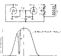 4Ь5 КС FREQUENCY TO PLATE TERMINAL OF FIRST I-F TUBE THRU 2. OF COAXIAL LINE о -i- 12AX7 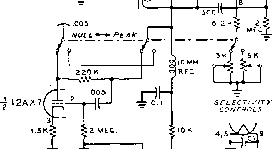 - в +200-300 v, - 6.3 v. Li = Sfl/i>-at/A/vf V6 CHOKE {о.е-б.омн) LZ=GffAySLIffNE LOOPSTICK COIL Figure 40 Q-MULTIPLIER NULL CIRCUIT Tbe addition of a second triode permits the 0-Multiplier to be userf for nu ing out an unwanted hetrodyne. the intermediate frequency, and the loss resistance of the circuit is neutralized by the positive feedback circuit composed of C3 and the vacuum tube. Too great a degree of positive feedback will cause the circuit to break into oscillation. At the resonant frequency, the impedance of the tuned circuit is very high, and when shunted across an i-f stage will have little effect upon the signal. At frequencies removed from resonance, the impedance of the circuit is low, resulting in high attenuation of the i-f signal. The resonant frequency of the Q-muItiplier may by varied by changing the value of one of the components in the tuned circuit. The Q-multiplier may also be used to null a signal by employing negative feedback to control the plate resistance of an auxiliary amplifier stage as shown in figure 40. Since the grid-cathode phase shift through the Q-multiplier is zero, the plate resistance of a second tube may be readily controlled by placing it across the Q-multiplier. At resonance, the high negative feedback drops the plate resistance of V2, shunting the i-f circuit. Off resonance, the feedback is reduced and the plate resistance of V2 rises, reducing the amount of signal attenuation in the i-f strip. A circuit combining both the peak and null features is shown in figure 41. Figure 41 SCHEMATIC OF A 455KC Q-MULTIPLIER Coil Ll is required to tune out the reactance of the coaxial line. It is adjusted for maximum signal response. Ll may be omitted if the Q-multiplier is connected to the receiver with о short length of wire, and the i-f transformer *yithin the receiver is retuned. may be used as a second detector in a receiver in place of the usual diode detector. The diode is an envelope detector (section 12-1) and develops a d-c output voltage from a single r-f signal, and audio beats from two or more input signals. A product detector (figure 42) requires that a local carrier voltage be present in order to produce an audio output signal. R-F SICNAL
> AUDIO OUTPUT The Product Detector A version of the common mixer or converter stage Figure 42 THE PRODUCT DETECTOR Audio output signal is developed only when local oscillator is on. 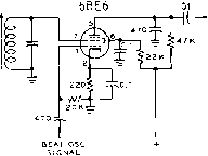 AUDIO OUT IrF SIC. 12AU7 V2 V3 12AU7  AUDIO OUT Figure 43 PENTAGRID MIXER USED AS PRODUCT DETECTOR Such a detector is useful for single sideband work, since the inter-modulation distortion is extremely low. A pentagrid product detector is shown in figure 43. The incoming signal is applied to grid 3 of the mixer tube, and the local oscillator is injected on grid 1. Grid bias is adjusted for operation over the linear portion of the tube characteristic curve. When grid 1 injection is removed, the audio output from an unmodulated signal applied to grid 3 should be reduced approximately ЗО to 40 db below normal detection level. When the frequency of the local oscillator is synchronized with the incoming carrier, amplitude modulated signals may be received by exalted carrier reception, wherein the local carrier substitutes for the transmitted carrier of the a-m signal. Three triodes may be used as a product detector (figure 44). Triodes VI and V2 act as cathode followers, delivering the sideband signal and the local oscillator signal to a grounded grid triode (V3) which functions as the mixer stage. A third version of the product detector is illustrated in figure 45- A twin triode tube is used. Section VI functions as a cathode follower amplifier. Section V2 is a Figure 44 TRIPLE-TRlODE PRODUCT DETECTOR V7 and V2 act as cathode followers, delivering sideband signal and local oscillator signal to grounded grid triode mixer (V3). 12AU7 Vi + V2 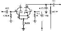 AUDIO OUT BEATOSC, + SliNAL Figure 45 DOUBLE-TRIODE PRODUCT DETECTOR plate detector, the cathode of which is common with the cathode follower amplifier. The local oscillator signal is injected into the grid circuit of tube V2.    Figure 46 EXPLODED VIEW OF COLLINS MECHANICAL FILTER  Generation of Radio Frequency Energy A radio communication or broadcast transmitter consists of a source of radio frequency power, or carrier; a system for modulating the carrier whereby voice or telegraph keying or other modulation is superimposed upon it; and an antenna system, including feed line, for radiating the intelligence-carrying radio frequency power. The power supply employed to convert primary power to the various voltages required by the r-f and modulator portions of the transmitter may also be considered part of the transmitter. Voice modulation usually is accomplished by varying either the amplitude or the frequency of the radio frequency carrier in accordance with the components of intelligence to be transmitted. Radiotelegraph modulation (keying) normally is accomplished either by interrupting, shifting the frequency of, or superimposing an audio tone on the radio-frequency carrier in accordance with the dots and dashes to be transmitted. The complexity of the radio-frequency generating portion of the transmitter is dependent upon the power, order of stability, and frequency desired. An oscillator feeding an antenna directly is the simplest form of radio-frequency generator. A modern high-frequency transmitter, on the other hand, is a very complex generator. Such an equipment usually comprises a very stable crystal-controlled or self-controlled oscillator to stabilize the output frequency, a series of frequency multipliers, one or more amplifier stages to increase the power up to the level which is desired for feeding the antenna system, and a filter system for keeping the harmonic energy generated in the transmitter from being fed to the antenna system. 13-1 Self-Controlled Oscillators In Chapter Four, it was explained that the amplifying properties of a tube having three or more elements give it the ability to generate an alternating current of a frequency determined by the components associated with it. A vacuum tube operated in such a circuit is called an oscillator, and its function is essentially to convert direct current into radio-frequency alternating current of a predetermined frequency. Oscillators for controlling the frequency of conventional radio transmitters can be divided into two general classes: self-controlled and crystal-controlled. There are a great many types of self-controlled oscillators, each of which is best suited 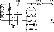 (a) shunt-fed hartley (в) shunt-fed colpitts о -в лов лов о о +в (с) TUNED plate tuned GRID 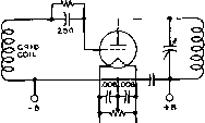 (d) tuned-plate untuned grid -Wr-\ о -b6 O+b (e) electron coupled 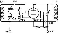 (f) colpitts electron coupled 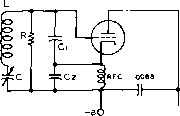 (g) clapp 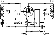 (h) clapp electron coupled Figure 1 COMMON TYPES OF SEUF-EXCITED OSCILLATORS Fixerf eapacHor values ore typical, but will vary somewhat with the application. In the Clapp oscillator circuits (G) and (H), capacitors Cj and C2 should have a reactance of 50 to 100 ohms at the operating frequency of the oscillator. Tuning of these two oscillators is accomplished by capacitor C. In the circuits of (E), (F), and (H), tuning of the fonk circuit in the plate of the oscillator tube will have relatively small effect on the frequency of oscillation. The plate tank circuit also may, if desired, be tuned to a harmonic of the osciffation frequency, or о broadly resonant circuit may be used In this circuit position. to a particular application. They can further be subdivided into the classifications of: negative-grid oscillators, electron-orbit oscillators, negative-resistance oscillators, velocity modulation oscillators, and magnetron oscillators. Negative-Grid A negative-grid oscillator is Oscillators essentially a vacuum-tube amplifier with a sufficient portion of the output energy coupled back into the input circuit to sustain oscillation. The con- trol grid is biased negatively with respect to the cathode. Common types of negative-grid oscillators are diagrammed in figure 1. The Hartley Illustrated in figure 1 (A) is the oscillator circuit which finds the most general application at the present time; this circuit is commonly called the Hartley. The operation of this oscillator will be described as an index to the operation of all negative-grid oscillators; the only real differ- 1 ... 20 21 22 23 24 25 26 ... 80 |
||||||||||||||
|
© 2026 AutoElektrix.ru
Частичное копирование материалов разрешено при условии активной ссылки |