 |
 |
 |
| Главная Журналы Популярное Audi - почему их так назвали? Как появилась марка Bmw? Откуда появился Lexus? Достижения и устремления Mercedes-Benz Первые модели Chevrolet Электромобиль Nissan Leaf |
Главная » Журналы » Simple coaxial reflectometer 1 ... 21 22 23 24 25 26 27 ... 80 HANDBOOK Oscillators ence between the various circuits is the manner in which energy for excitation is coupled from the plate to the grid circuit. When plate voltage is applied to the Hartley oscillator shown at (A), the sudden flow of plate current accompanying the application of plate voltage will cause an electro-magnetic field to be set up in the vicinity of the coil. The building-up of this field will cause a potential dr6p to appear from turn-to-turn along the coil. Due to the inductive coupling between the portion of the coil in which the plate current is flowing and the grid portion, a potential will be induced in the grid portion. Since the cathode tap is between the grid and plate ends of the coil, the induced grid voltage acts in such a manner as to increase further the plate current to the tube. This action will continue for a short period of time determined by the inductance and capacitance of the tuned circuit, until the flywheel effect of the tuned circuit causes this action to come to a maximum and then to reverse itself. The plate current then decreases, the magnetic field around the coil also decreasing, until a minimum is reached, when the action starts again in the original direction and at a greater amplitude than before. The amplitude of these oscillations, the frequency of which is determined by the coil-capacitor circuit, will increase in a very short period of time to a limit determined by the plate voltage of the oscillator tube. The Cotpitts Figure 1 (B) shows a version of the Colpitts oscillator. It can be seen that this is essentially the same circuit as the Hartley except that the ratio of a pair of capacitances in series determines the effective cathode tap, instead of actually using a tap on the tank coil. Also, the net capacitance of these two capacitors comprises the tank capacitance of the tuned circuit. This oscillator circuit is somewhat less susceptible to parasitic (spurious) oscillations than the Hartley. For best operation of the Hartley and Colpitts oscillators, the voltage from grid to cathode, determined by the tap on the coil or the setting of the two capacitors, normally should be from 1/3 to 1/5 that appearing between plate and cathode. The T.P.T.G. The tuned-plate tuned-grid oscillator illustrated at (C) has a tank circuit in both the plate and grid circuits. The feedback of energy from the plate to the grid circuits is accomplished by the plate-to-grid inter-electrode capacitance within the tube. The necessary phase reversal in feedback voltage is provided by tuning the grid tank capacitor to the low side of the de- sired frequency and the plate capacitor to the high side. A broadly resonant coil may be substituted for the grid tank to form the T.N.T. oscillator shown at (D). Electron-Coupted In any of the oscillator cir-Oscillators cuits just described it is possible to take energy from the oscillator circuit by coupling an external load to the tank circuit. Since the tank circuit determines the frequency of oscillation of the tube, any variations in the conditions of the external circuit will be coupled back into the frequency determining portion of the oscillator. These variations will result in frequency instability. The frequency determining portion of an oscillator may be coupled to the load circuit only by an electron stream, as illustrated in (E) and (F) of figure 1. When it is considered that the screen of the tube acts as the plate to the oscillator circuit, the plate merely acting as a coupler to the load, then the similarity between the cathode-grid-screen circuit of these oscillators and the cathode-grid-plate circuits of the corresponding prototype can be seen. The electron-coupled oscillator has good stability with respect to load and voltage variation. Load variations have a relatively small effect on the frequency, since the only coupling between the oscillating circuit and the load is through the electron stream flowing through the other elements to the plate. The plate is electrostatically shielded from the oscillating portion by the bypassed screen. The stability of the e.c.o. with respect to variations in supply voltages is explained as follows: The frequency will shift in one direction with an increase in screen voltage, while an increase in plate voltage will cause it to shift in the other direction. By a proper proportioning of the resistors that comprise the voltage divider supplying screen voltage, it is possible to make the frequency of the oscillator substantially independent of supply voltage variations. The Clapp A relatively new type of oscillator Oscillator circuit which is capable of giving excellent frequency stability is illustrated in figure IG. Comparison between the more standard circuits of figure lA through IF and the Clapp oscillator circuits of figures IG and IH will immediately show one marked difference: the tuned circuit which controls the operating frequency in the Clapp oscillator is series resonant, while in all the more standard oscillator circuits the frequency controlling circuit is parallel resonant. Also, the capacitors C, and Cj are relatively large in terms of the usual values for a Colpitts oscil- lator. In fact, the value of capacitors Cj and Cj will be in the vicinity of 0.001 /rfd. to 0.0025 fitd. for an oscillator which is to be operated in the 1.8-Mc. band. The Clapp oscillator operates in the following manner: at the resonant frequency of the oscillator tuned circuit (L, C) the impedance of this circuit is at minimum (since it operates in series resonance) and maximum current flows through it. Note however, that Cj and Cj also are included within the current path for the series resonant circuit, so that at the frequency of resonance an appreciable voltage drop appears across these capacitors. The voltage drop appearing across Cj is applied to the grid of the oscillator tube as excitation, while the amplified output of the oscillator tube appears across Cj as the driving power to keep the circuit in oscillation. Capacitors Cj and Cj should be made as large in value as possible, while still permitting the circuit to oscillate over the full tuning range of C. The larger these capacitors are made, the smaller will be the coupling between the oscillating circuit and the tube, and consequently the better will be oscillator stability with respect to tube variations. High tubes such as the 6AC7, 6AG7, and 6CB6 will permit the use of larger values of capacitance at Cl and Cj than will more conventional tubes such as the 6SJ7, 6V6, and such types. In general it may be said that the reactance of capacitors Cj and Cj should be on the order of 40 to 120 ohms at the operating frequency of the oscillator-with the lower values of reactance going with high-Gn, tubes and the higher values being necessary to permit oscillation with tubes having Сц, in the range of 2000 micromhos such as the 6SJ7. It will be found that the Clapp oscillator will have a tendency to vary in power оифиг over the frequency range of tuning capacitor C. The output will be greatest where С is at its largest setting, and will tend to fall off with С at minimum capacitance. In fact, if capacitors Ci and Cj have too large a value the circuit will stop oscillation near the minimum capacitance setting of C. Hence it will be necessary to use a slightly smaller value of capacitance at and Cj (to provide an increase in the capacitive reactance at this point), or else the frequency range of the oscillator musr be restricted by paralleling a fixed capacitor across С so that its effective capacitance at minimum setting will be increased to a value which will sustain oscillation. In the triode Clapp oscillator, such as shown at figure IG, оифШ voltage for excitation of an amplifier, doubter, or isolation stage normally is taken from the cathode of the oscillator tube by capacitive coupling to the grid of the next tube. However, where greater iso- lation of succeeding stages from the oscillating circuit is desired, the electron-coupled Clapp oscillator diagrammed in figure Ш may be used. Оифи1 then may be taken from the plate circuit of the tube by capacitive coupling with either a tuned circuit, as shown, or with an r-f choke or a broadly resonant circuit in the plate return. Alternatively, energy may be coupled from the ouфut circuit Lj-Cj by link coupling. The considerations with regard to Cl, Cj, and the grid tuned circuit are the same as for the triode oscillator arrangement of figure IG. Negative Resist- Negative-resistance oscil-ance Oscillators lators often are used when unusually high frequency stability is desired, as in a frequency meter. The dynatron of a few years ago and the newer transitron are examples of oscillator circuits which make use of the negative resistance characteristic between different elements in some multi-grid tubes. In the dynatron, the negative resisrance is a consequence of secondary emission of electrons from the plate of a tetrode tube. By a proper proportioning of the electrode voltage, an increase in screen voltage will cause a decrease in screen currenr, since the increased screen voltage will cause the screen to attract a larger number of the secondary electrons emitted by the plate. Since the net screen current flowing from the screen supply will be decreased by an increase in screen voltage, it is said that the screen circuit presents a negative resistance. If any type of tuned circuit, or even a resistance-capacitance circuit, is connected in series with the screen, the arrangement will oscillate-provided, of course, that the external circuit impedance is greater than the negative resistance. A negative resistance effect similar to the dynatron is obtained in the transitron circuit, which uses a pentode with the suppressor coupled to the screen. The negative resistance in this case is obtained from a combination of secondary emission and inter-electrode coupling, and is considerably more stable than that obtained from uncontrolled secondary emission alone in the dynatron. A representative transitron oscillator circuit is shown in figure 2. The chief distinction between a conventional negative grid oscillator and a negative resistance oscillator is that in the former the tank circuit must act as a phase inverter in order to permit the amplification of the tube to act as a negative resistance, while in the latter the tube acts as its own phase inverter. Thus a negative resistance oscillator requires only an untapped coil and a single capacitor HANDBOOK Oscillators 243 6SK7  0b+ 100- ijov. (a) transitron oscillator 6SN7 OR 6J6  о b+ 100- iso v. fi) CATHODE COUPLED OSCILLATOR Figure 2 TWO-TERMINAL OSCILLATOR CIRCUITS Both circuits may be used for an audio oscillator or for frequencies into fhe v-h-f ronge simply by placing a tank circuit funecf to the proper frequency where Indicated on the drawing. Recommerided values for the components are given below for both oscillators. TRANSITION OSCILLATOI Cj 0.01-/ifd. mica for r.f. 10./ifd. elect, {or o.f. Cj-0.00005-Mid. mico for r.f. O.l-ifd. poper for o.f. Cj-0.003-/j.fd. mica for r.f. 0.5-Mfd. paper for o.f. -0.01-/ifd. mica for r.f. B/ifd. elect, for o.f. Rj-220K H-watt carbon Rj-1800 ahms -watt carbon Rj-22K 2-watt carbon R4-22K 2-woft eorbon CATHODE-COUPLED OSCILLATOR Cl-0.00005-Atfd. mica for r.f. O.l-ifd. paper for oudio Cj-0.003-/ifd. mica for r.f. 8-MM. efeet. for audio Rl-47K й-wott carbon Rj-1K 1-wott carbon as the frequency determining tank circuit, and is classed as a two terminal oscillator. In fact, the time constant of an R/C circuit may be used as the frequency determining element and such an oscillator is rather widely used as a tunable audio frequency oscillator. The Franklin The Franklin oscillator makes Oscillator use of two cascaded tubes to obtain the negative-resistance effect (figure 3). The tubes may be either a pair of triodes, tetrodes, or pentodes, a dual triode, or a combination of a triode and a multi-grid tube. The chief advMtage of this oscillator circuit is that the frequency determining tank only has two terminals, and one side of the circuit is grounded. The second tube acts as a phase inverter to give an effect similar to that obtained with the dynatron or transitron, except rhat the effective transconductance is much higher. If the tuned circuit is omitted or is replaced by a resistor, the circuit becomes a relaxation oscillator or a multivibrator. Oscillator The Clapp oscillator has proved Stability to be inherently the mOst stable of all the oscillator circuits dis- cussed above, since minimum coupling between the oscillator tube and its associated tuned circuit is possible. However, this in- herently good stability is with respect to tube variations; instability of the tuned circuit with respect to vibration or temperature will of course have as much effect on the frequency of oscillation as with any other type of oscillator circuit. Solid mecheuiical construction of the components of the oscillating circuit, along with a small negative-coefficient compensating capacitor included as an element of the tuned circuit, usually will afford an adequate degree of oscillator stability. с о 7С  ►output  о О - в + Figure 3 THE FRANKLIN OSCILLATOR CIRCUIT A separate phase inverter tube is used in this oscillator to feed a portion of the output back to the input in the proper phase to sustain oscillation. The values of C; antf C2 should be as small as will permit oscillations to be sustained over fhe desired frequency range. V.F.O. Transmit- When used to control the fre- ter Controls quency of a transmitter in which there are stringent limitations on frequency tolerance, several precautions are taken to ensure that a variable frequency oscillator will stay on frequency. The oscillator is fed from a voltage regulated power supply, uses a well designed and temperature compensated tank circuit, is of rugged mechanical construction to avoid the effects of shock and vibration, is protected against excessive changes io ambient room temperature, and is isolated from feedback or stray coupling from other portions of the transmitter by shielding, filtering of voltage supply leads, and incorporation of one or more buffer-amplifier stages. In a high power transmitter a small amount of stray coupling from the final amplifier to the oscillator can produce appreciable degradation of the oscillator stability if both are on the same frequency. Therefore, the oscillator usually is operated on a subharmonic of the transmitter output frequency, with one or more frequency multipliers between the oscillator and final amplifier. 13-2 Quartz Crystal Oscillators Quartz is a naturally occuring crystal having a structure such that when plates are cut in certain definite relarionships to the crystal-lographic axes, these plates will show the piezoelectric effect-the plates will be deformed in the influence of an electric field, and, conversely, when such a plate is compressed or deformed in any way a potential difference will appear upon its opposite sides. The crystal has mechanical resonance, and will vibrate at a very high frequency because of its stiffness, the natural period of vibration depending upon the dimensions, the method of electrical excitation, and crystallographic orientation. Because of the piezoelectric properties, it is possible to cut a quartz plate which, when provided with suitable electrodes, will have the characteristics of a series resonant circuit with a very high L/C ratio and very high Q. The Q is several times as high as can be obtained with an inductor-capacitor combination in conventional physical sizes. The equivalent electrical circuit is shown in figure 4A, the resistance component simply being an acknowledgment of the fact that the Q, while high, does not have an infinite value. The shunt capacitance of the electrodes and associated wiring (crystal holder and socket, plus circuit wiring) is represented by the dotted portion of figure 4В. In a high frequency Lh о fLAHGElO (small)? ® о о LiO о о I CSTRAY I SHUNT) о о о о о Figure 4 EQUIVALENT ELECTRICAL CIRCUIT OF QUARTZ PLATE IN A HOLDER At (A) is shown the equivalent series-resonant circuit of the crystal itself, at (B) is shown how the shunt capacitance of the holder electrodes and associated wiring affects the circuit to the combination circuit of (C) which exhibits both series resonance and parallel resonance (anti-resonance), the separation In frequency between the two modes being very small and determined by the ratio of Сj to Сз- crystal this will be considerably greater than the capacitance component of an equivalent series L/C circuit, and unless the shunt capacitance is balanced out in a bridge circuit, the crystal will exhibit both resonant (series resonant) and anti-resonant (parallel resonant) frequencies, the latter being slightly higher than rhe series resonant frequency and approaching it as Cj is increased. The series resonance characteristic is employed in crysral filter circuits in receivers and also in certain oscillator circuits wherein the crystal is used as a selective feedback element in such a manner that the phase of the feedback is correct and the amplitude adequate only at or very close to the series resonant frequency of the crystal. While quartz, tourmaline, Rochelle salts, ADP, and EDT crystals all exhibit the piezoelectric effect, quartz is the material widely employed for frequency control. As the cutting and grinding of quartz plates has progressed to a high state of development and these plates may be purchased at prices which discourage the cutting and grinding by simple hand methods for ones own use, the procediu-e will be only lightly touched upon here. The crystal blank is cut from the raw quartz at a predetermined orientation with respect to the optical and electrical axes, the orientation determining the activity, temperature coefficient, thickness coefficient, and other characteristics. Various orientations or cuts having useful characteristics are illustrated in figure 5. HANDBOOK Crystal Oscillators 245 ZERO ТЕМРЕЙАТиДЕ COFFFtCIENT OSCILLATORS AND TlLTtRS Figure 5 ORIENTATION OF THE COMMON CRYSTAL CUTS  ZERO TEMPERATURE COEFFICIENT 0* OSCILLATORS FUNDAMENTAL AND SECOND HARMONIC ZERO TEMP COEFFICIENT CT OSCILLATORS AND FILTERS DQUCMNUT ZERO TEMPERATUR COEFFICIENT A MT LONGITUDINAL CRYSTAL e NT FLEXURE CRYSTAL LOW TEMP COEFFICIENT 45 FILTERS The crystal blank is then rough-ground almost to frequency, the frequency increasing in inverse ratio to the oscillating dimension (usually the thickness). It is then finished to exact frequency either by careful lapping, by etching, or plating. The latter process consists of finishing it to a frequency slightly higher than that desired and then silver plating the electrodes right on the crystal, the frequency decreasing as the deposit of silver is increased. If the crystal is not etched, it must be carefully scrubbed and *baked several times to stabilize it, or otherwise the frequency and activity of the crystal will change with time. Irradiation by X-rays recently has been used in crystal finishing. Unplated crystals usually are mounted in pressure holders, in which two electrodes are held against the crystal faces under slight pressure. Unplated crystals also are sometimes mounted in an air-gap holder, in \idiich there is a very small gap between the crystal and one or both electrodes. By making this gap variable, the frequency of the crystal may be altered over narrow limits (about 0.3% for certain types). The temperature coefficient of frequency for various crystal cuts of the -T rotated family is indicated in figure 5- These angles are rypical, but crystals of a certain cut will vary slightly. By controlling the orientation and dimensioning, the turning point (point of zero temperature coefficient) for a ВТ cut plate may be made either lower or higher than the 75 degrees shown. Also, by careful control of axes and dimensions, it is possible to get AT cut crystals with a very flat temperature-frequency characteristic. The first quartz plates used were either Y cut or X cut. The former had a very high temperature coefficient which was discontinuous, causing the frequency to jump at certain critical temperatures. The X cut had a moderately bad coefficient, but it was more continuous, and by keeping the crystal in a temperature controlled oven, a high order of stability could be obtained. However, the X cut crystal was considerably less active than the Y cut, especially in the case of poorly ground plates. For frequencies between 500 kc. and about 6 Mc, the AT cut crystal now is the most widely used. It is active, can be made free from spurious responses, and has an excellent temperature characteristic. However, above about 6 Mc. it becomes quite thin, and a difficult production job. Between 6 Mc. and about 12 Mc, the ВТ cut plate is widely used. It also works well between 500 kc. and 6 Mc, but the AT cut is raore desirable when a high order of stability is desired and no crystal oven is employed. For low frequency operation on the order of 100 kc, such as is required in a frequency standard, the GT cut crystal is recommended, though CT and DT cuts also are widely used for applications between 50 and 500 kc. The CT, DT, and GT cut plates are known as contour cuts, as these plates oscillate along the long dimension of the plate or bar, and are much smaller physically than would be the case for a regular AT or ВТ cut crystal for the same frequency. Crystal Holders Crystals normally are purchased ready mounted. The best type mount is determined by the type crystal and its application, and usually an optimum mounting is furnished with the crystal. However, certain features are desirable in all holders. One of these is exclusion of moisture and prevention of electrode oxidization. The best means of accomplishing this is a metal holder, hermetically sealed, with glass insulation and a metal-to-glass bond. However, such holders are more expensive, and a ceramic or phenolic holder with rubber gasket will serve where requirements are not too exacting. Temperoture Control; Where the frequency tol-Crystal Ovens erance requirements are not too stringenrand the ambient temperature does not include extremes, an AT-cut plate, or a BT-cut plate with optimum (mean temperature) turning point, will often provide adequate stability without resorting to a temperature controlled oven. However, for broadcast stations and other applications where very close tolerances must be maintained, a thermostatically controlled oven, adjusted for a temperature slightly higher than the highest ambient likely to be encountered, must of necessity be employed. Harmonic Cut Just as a vibrating string can Crystals be made to vibrate on its har- monics, a quartz crystal will exhibit mechanical resonance (and therefore electrical resonance) at harmonics of its fundamental frequency. When employed in the usual holder, it is possible to excite the crystal only on its odd harmonics (overtones). By grinding the crystal especially for harmonic operation, it is possible to enhance its operation as a harmonic resonator. ВТ and AT cut crystals designed for optimum operation on the 3d, 5th and even the 7th harmonic are available. The 5th and 7th harmonic types, especially the latter, require special holder and oscillator circuit precautions for satisfactory operation, bur the 3d harmonic type needs little more considerarion than a regular fundamental type. A crystal ground for optimum operation on a particular harmonic may or may not be a good oscillator on a different harmonic or on the fundamental. One interesting characteristic of a harmonic cut crystal is that its harmonic frequency is not quite an exact multiple of its fundamental, though the disparity is very small. The harmonic frequency for w4iich the crystal was designed is the working frequency. It is not the fundamental since the crystal itself actually oscillates on this working frequency when it is functioning in the proper manner. When a harmonic-cut crystal is employed, a selective tuned circuitmust be employed somewhere in the oscillator in order to discrimi- EXCJTATION  BASIC PIERCE OSCILLATOR HOT-CATHODE PIERCE* OSCILLATOR Figure 6 THE PIERCE CRYSTAL OSCILLATOR CIRCUIT Shown or (A) is the basic Pierce crystal oscillator circuit. A capacitance of 10 to 75 ffifd. normally will be required at Ci for optimum operation. If a plate supply voltage higher than indicated Is to be used, RFCj may be replaced by a 22,000-ohm 2-watt resistor. Shown at (B) Is an alternative arrangement with the r-f ground moved to the plate, and with the cathode floating. This alternative circuit has the advantage that the full r-f voltage developed across the crystal may be used as excitation to the next stage, since one side of the crystal is grounded. nate against the fundamental frequency or undesired harmonics. Otherwise the crystal might notalways oscillate on the intended frequency. For this reason the Pierce oscillator, later described in this chapter, is not suitable for use with harmonic-cut crystals, because the only tuned element in this oscillator circuit is the crystal itself. Crystal Current; For a given crystal op- Heating and Fracture erating as an anti-resonant tank in a given oscillator at fixed load impedance and plate and screen voltages, the r-f currenr through the crystal will increase as the shunr capacirance Cj of figure 4 is increased, because this effectively increases the step-up ratio of Cj to Cj. For a given shunt capacitance, Cj, the crystal current for a given crystal is directly proportional to the r-f voltage across Cj. This voltage may be measured by means of a vacuum tube voltmeter having a low input capacitance, and such a measurement is a more pertinent one than a reading of r-f current by means of a thermogalvanometer inserted in series with one of the leads to the crystal holder. The function of a crystal is to provide accurate frequency control, and unless it is used in such a manner as to take advantage of its inherent high stability, there is no point in using a crystal oscillator. For rhis reason a HANDBOOK Crystal Oscillators 247 crystal oscillator should not be run at high plate input in an attempt to obtain considerable power directly out of the oscillator, as such operation will cause the crystal to heat, with resultant frequency drift and possible fracture. 13-3 Crystal Oscillator Circuits Considerable confusion exists as to nomenclature of crystal oscillator circuits, due to a tendency to name a circuit after its discoverer. Nearly all the basic crystal oscillator circuits were either first used or else developed independently by G. W. Pierce, but he has not been so credited in all the literature. Use of the crystal oscillator in master oscillator circuits in radio transmitters dates back to about 1924 when the first application articles appeared. The Pierce The circuit of figure 6A is the sim-Oscillator plest crystal oscillator circuit. It is one of those developed by Pierce, and is generally known among amateurs as the Pierce oscillator. The crystal simply replaces the tank circuit in a Colpitts or ultra-audion oscillator. The r-f excitation voltage available to the next stage is low, being somewhat less than that developed across the crystal. Capacitor Cj will make more of the voltage across the crystal available for excitation, and sometimes will be found necessary to ensure oscillation. Its value is small, usually approximately equal to or slightly greater than the stray capacitance from the plate circuit to ground (including the grid of the stage being driven). If the r-f choke has adequate inductance, a crystal (even a harmonic cut crysral) will almost invariably oscillate on its fundamental. The Pierce oscillator therefore cannot be used with harmonic cut crystals. The circuit at (B) is the same as that of (A) except that the plate instead of the cathode is operated at ground r-f potential. All of the r-f voltage developed across the crystal is available for excitation to the next stage, but still is low for reasonable values of crystal current. For best operation a tube with low heater-cathode capacitance is required. Excitation for the next stage may also be taken from the cathode when using this circuit. The circuit shown in figure 7A is also one used by Pierce, but is more widely referred to as the Miller oscillatot. To avoid Tuned-Plate Crystal Oscillator confusion, we shall refer to it as the tuned-plate crystal oscillator. It is essentially an Armstrong or tuned plate-tuned grid oscillator with the crystal replacing the usual L-C grid tank. The plate tank must be tuned to a frequency slightly higher than the anti-resonant (parallel resonant) frequency of the crystal. Whereas the Pierce circuits of figure 6 will oscillate at (or very close to) the anti-resonant frequency of the crystal, the circuits of figure 7 will oscillate at a frequency a little above the anti-resonant frequency of the crystal. The diagram shown in figure 7A is the basic circuit. The most popular version of the tuned-plate oscillator employs a pentode or beam tetrode with cathode bias to prevent excessive plate dissipation when the circuit is not oscillating. The cathode resistor is optional. Its omission will reduce both crystal current and oscillator efficiency, resulting in somewhat more ouфut for a given crystal current. The tube usually is an audio or video beam pentode or tetrode, the plate-grid capacitance of such tubes being sufficient to ensure stable oscillation but not so high as to offer excessive feedback with resulting high crystal current. The 6AG7 makes an excellent all-around tube for this type circuit. Pentode The usual type of crystai- Hormonic Crystal controlled h-f transmitter Oscillator Circuits operates, at least part of the time, on a frequency which is an integral multiple of the operating frequency of the controlling crystal. Hence, oscillator circuits which are capable of providing output on the crystal frequency if desired, but which also can deliver output energy on harmonics of the crystal frequency have come into wide use. Four such circuits which have found wide application are illustrated in figures 7C, 7D, 7E, and 7F. The circuit shown in figure 7C is recommended for use with harmonic-cut crystals when output is desired on a multiple of the oscillating frequency of the crystal. As an example, a 25-Mc. harmonic-cut crystal may be used in this circuit to obtain output on 50 Mc, or a 48-Mc. harmonic-cut crystal may be used to obtain output on the 144-Mc. amateur band. The circuit is not recommended for use with the normal rype of fundamental-frequency crystal since more output with fewer variable elements can be obtained with the circuits of 7D and 7F. The Pierce-harmonic circuit shown in figure 7D is satisfactory for many applications which require very low crystal current, but has the disadvantage that both sides of the crystal are above ground potential. The Tri-tet circuit of figure 7E is widely used and can 6J5, ETC.  -±r .002 О ~ о о о + f 50 V. BASIC TUNED-PLATE OSCILLATOR ® 6V6, 6AQ5, ETC,  47 к o о о о +250 V. RECOMMENDED TUNED-PLATE OSCILLATOR 6AG7,6AQ5,5763 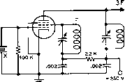 SPECIAL CIRCUIT FOR USE WITH HARMONIC-CUT CRYSTAL. 6AG7 F, 2F, 3F 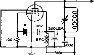 6+250 V. PIERCE HARMONIC CIRCUIT 6AG7 30K о гоо jujuF, / о F. 2F. 3F, 4F 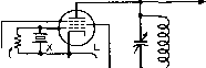 47 И -Wr- TRITET CIRCUIT O+250 v. 6AG7 F. 2F. 3F. 4F 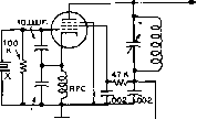 150 UUF. 6+250 V. COLPITTS HARMONIC OSCILLATOR ® Figure 7 COMMONLY USED CRYSTAL OSCILLATOR CIRCUITS Shown at (A) Is the basic tuned-plata crystal oscillator with a triada oscillator tuba. The plate tank must be turiad on the law-capacitar\ce side pf resonance fo sustain oscillation. (B) shows the tuned-plate oscillator as it Is normally used, with an a-f power pentode to permit high output with relatiyely liw crystal current. Schematics (C), (D), (E), and (F) Illustrate crystal oscillator circuits which can deliver moderate output energy an harmonics of the oscillating frequency of the crystal. (C) shows a special circuit whfch will permit use of a harmonic-cut crystal to obtain output energy well into the v-h-f range. (D) is valuable when extremely low crystal current is a requirement, but delivers relatively low output. (E) is commonly used, but is subject to crystal damage if the cathode circuit is mistuned. (F) is recommended as the most genera/fy satisfactory from the standpairits of; low crystal current regardless of mts-adjustment, gaad output on harmonic frequencies, one side of crystal is grounded, will oscillate with crystals from 1.5 io 10 Mc. without adjustment, output tank may be tuned to the crystal frequency for fundamental output without stopping oscillation or changing frequency. give excellent output with low crystal current. However, the circuit has the disadvantages of requiring a cathode coil, of requiring careful setting of the variable cathode capacitor to avoid damaging the crystal when changing frequency ranges, and of having both sides of the crystal above ground potential. The Colpitts harmonic oscillator of figure 7F is recommended as being the most generally satisfactory harmonic crystal oscillator circuit since it has the following advantages: (1) the circuit will oscillate with crystals over a very wide frequency range with no change other than plugging in or switching in the desired crystal; (2) crystal current is ex- tremely low; (3) one side of the crystal is grounded, which facilitates crystal-switching circuits; (4) the circuit will operate straight through without frequency pulling, or it may be operated with output on the second, third, or fourth harmonic of the crystal frequency. Crystal Oscillatar Tuning The tunable circuits of all oscillators illustrated should be tuned for maximum оифиг as indicated by maximum excitation to the following stage, except that the oscillator tank of tuned-plate oscillators (figure 7A and figure 7B) should be backed off slightly towards the low capacitance side from HANDBOOK All-band Crystal Oscillator 24 9 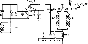 7T. 30/5 BSW MINIOUCTOR (2.0 JJH) NOT-£S I. \\-1Ы1И {г^ OF Biw № зон) Z. Lz=/.6jj {i оРв^>у*зооз) 3, FOff JSOMSTEK OPERATION ADD S MJJF CONDENSER BETWEEN PINS 4 t 3 OF CAST. PLATE COIL = S5 JJH, (zf OF BSAHtlOie) 4, X= 7 MC. CBYSTAL FOn HARMONIC OPERATION Figure 8 ALL-BAND 6AG7 CRYSTAL OSCILLATOR CAPABLE OF DRIVING BEAM PENTODE TUBE maximum оифиг, as the oscillator then is in a more stable condition and sure to start immediately when power is applied. This is especially important when the oscillator is keyed, as for break-in c-w operation. Crystal Switching It is desirable to keep stray shunt capacitances in the crystal circuit as low as possible, regardless of the oscillator circuit. If a selector switch is used, this means that both switch and crystal sockets must be placed close to the oscillator tube socket. This is especially true of harmonic-cut crystals operating on a comparatively high frequency. In fact, on the highest frequency crystals it is preferable to use a turret arrangement for switching, as the stray capacitances can be kept lower. Crystal Oscillator When the crystal oscillator Keying is keyed, it is necessary that crystal activity and oscillator-tube transconductance be moderately high, and that oscillator loading and crystal shunt capacitance be low. Below 2500 kc. and above 6 Mc. these considerations become especially important. Keying of the plate voltage (in the negative lead) of a crystal oscillator, with the screen voltage regulated at about 150 volts, has been found to give satisfactory results. A Versatile 6AG7 Crystal Oscillator The 6AG7 tube may be used in a modified Tri-tct crystal oscillator, capable of delivering sufficient power on all bands from 160 meters through 10 meters to fully drive a pentode tube, such as the 807, 2E26 or 6146. Such an oscillator is extremely useful for portable or mobile work, since it combines all essential exciter functions in one tube. The circuit of this oscillator is shown in figure 8. For 160, 80 and 40 meter operation the 6AG7 functions as a tuned-plate oscillator. Fundamental frequency crystals are used on these three bands. For 20, 15 and 10 meter operation the 6AG7 functions as a Tri-tet oscillator with a fixed-tuned cathode circuit. The impedance of this cathode circuit does not affect operation of the 6AG7 on the lower frequency bands so it is left in the circuit at all times. A 7-Mc. crystal is used for fundamental output on 40 meters, and for harmonic оифиг on 20, 15 and 10 meters. Crystal current is extremely low regardless of rhe output frequency of the oscillator. The plate circuit of the 6AG7 is capable of tuning a frequency range of 2:1, requiring only two ouфut coils: one for 80-40 meter operation, and one for 20, 15 and 10 meter operation. In some cases it maybe necessary to add 5 micromicrofarads of external feedback capacity between the plate and control grid of the 6AG7 tube to sustain oscillation with sluggish 160 meter crystals. Triode Overtone The recent development of Oscillators reliable overtone crystals capable of operation on the third, fifth, seventh (or higher) overtones has made possible v-h-f ouфut from a low frequency crystal by the use of a double triode regenerative oscillator circuit. Some of the new twin triode tubes such as the 12AU7, 12AV7 and 6j6 are especially satisfactory when used in this type of circuit. Crystals that are ground for Overtone service may be made to oscillate on odd overtone frequencies other than the one marked on the crystal holder. A 24-Mc. overtone crystal, for example, is a specially ground 8-Mc. crystal operating on its third overtone. In the proper circuit it may be made to oscillate on 40 Mc. (fifth overtone), 56 Mc. (seventh overtone), or 72 Mc. (ninth overtone). Even the ordinary 8-Mc. crystals not designed for overtone operation may be made to oscillate readily on 24 Mc. (third overtone) in these circuits. A variety of overtone oscillator circuits is shown in figure 9- The oscillator of figure 9A is attributed to Frank Jones, W6AJF. The first section of the 6j6 dual triode comprises a regenerative oscillator, with output on either the third or fifth overtone of the crystal frequency. The regenerative loop of this oscillator consists of a condenser bridge made up of Cj and Cj, with the ratio CjCj determining the amount of regenerative feedback in the circuit. With X X 7- 3FOR5F -Г =50 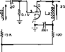 f*e,9,10 OR 15 F 0 JONES HARMONIC OSCILLATOR 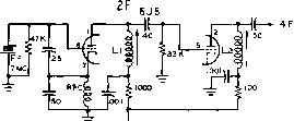 FOR 7 MC. CflfSTAL +300 V. \ = ZST. 24 ON NA TIONAL XRSO FORM L2= sr. IS ON NATIONAL XRSO FORM (B) COLPITTS HARMONIC OSCILLATOR I2AU7 F =6uc.- -Tiui- e2K 1 .001 La e.2K 6.9F FOR SMC. CRySTAL +30(1 L I = 9 7; e JC)53 S* If MINIDUCTOR LZ = 4riH003 Bin/MINIDUCTOR THESE COILS MADE FROM SINGLE SECTION OF MINIDUCTOR. ONE TURN BROKEN TO Ol l/IDB INDUCTOR INTO TWO COILS. (Q REGENERATIVE HARMONIC OSCILLATOR ,001 F=eMC. 12 AT? 1/5 i i L2 i.OOl ioo 1000% [/SO 5 Ы1 0.1 M e-III)-tv- F=eMc. - 6.9F L£ Ll = /Or* $011 BSW MINIDUCTOR, ГАРАГЗГ. FROM GRID END @ REGENERATIVE HARMONIC OSCILLATOR I2AT7 (or 6AB4) F= 144 MC. +ioov. l i = j г /a, o. SPACED LZ = IT. HOOKUP WIRE, D. (§) CATHODE FOLLOWER OVERTONE OSCILLATOR © V.H.F. OVERTONE OSCILLATOR Figure 9 VARIOUS TYPES OF OVERTONE OSCILLATORS USING MINIATURE DOUBLE-TRIODE TUBES an 8-,VJc. crystal, output from the first section of the 6j6 tube may be obtained on either 24 Mc. or 40 Mc, depending upon the resonant frequency of the plate circuit inductor, Lj. The second half of the 6j6 acts as a frequency multiplier, its plate circuit, Lj, tuned to the sixth or ninth harmonic frequency when Li is tuned to the third overtone, or to the tenth harmonic frequency when Lj is tuned to the fifth overtone. Figure 9B illustrates a Colpitts overtone oscillator employing a 6j6 tube. This is an outgrowth of the Colpitts harmonic oscillator of figure 7F. The regenerative loop in this case consists of C Cj and RFC between the grid, cathode and ground of the first section of the 6j6. The plate circuit of the first section is tuned to the second overtone of the crystal, and the second section of the 6j6 doubles to the fourth harmonic of the crystal. This circuit is useful in obtaining 28-Mc. output from a 7-Mc. crystal and is highly popular in mobile work. The circuit of figure 9C shows a typical regenerative overtone oscillator employing a 12AU7 double triode tube. Feedback is controlled by the number of turns in L, and the coupling between Lj and L,.Only enough feed- 1 ... 21 22 23 24 25 26 27 ... 80 |
|
© 2026 AutoElektrix.ru
Частичное копирование материалов разрешено при условии активной ссылки |