 |
 |
 |
| Главная Журналы Популярное Audi - почему их так назвали? Как появилась марка Bmw? Откуда появился Lexus? Достижения и устремления Mercedes-Benz Первые модели Chevrolet Электромобиль Nissan Leaf |
Главная » Журналы » Simple coaxial reflectometer 1 ... 22 23 24 25 26 27 28 ... 80 back should be employed to maintain proper oscillation of the crystal. Excessive feedback will cause the first section of the 12AU7 to oscillate as a self-excited TNT oscillator, independent of the crystal. A variety of this circuit is shown in figure 9D, wherein a tapped coil, Ll, is used in place of the two separate coils. Operation of the circuit is the same in either case, regeneration now being controlled by the placement of the tap on L. A cathode follower overtone oscillator is shown in figure 9E. The cathode coil, Li, is chosen so as to resonate with the crystal and tube capacities just below the third overtone frequency of the crystal. For example, with an 8-Mc. crystal, L3 is tuned to 24 Mc, Li resonates with the circuit capacities to 23.5 Mc, and the harmonic tank circuit of the second section of the 12AT7 is tuned either to 48 Mc or 72 Mc. If a 24-Mc. overtone crystal is used in this circuit, L3 may be tuned to 72 Mc, Li resonates with the circuit capacities to 70 \5c, and the harmonic tank circuit, Lj, is tuned to 144 Mc. If there is any tendency towards self-oscillation in the circuit, it may be eliminated by a small amount of inductive coupling between Lj and L3. Placing these coils near each other, with the winding of Lj correctly polarized with respect to L3 will prevent self-oscillation of the circuit. The use of a 144-Mc, overtone crystal is illustrated in figure 9F. A 6AB4 or one-half of a 12AT7 tube may be used, with output directly in the 2-meter amateur band. A slight amount of regeneration is provided by the one turn link, Lj, which is loosely coupled to the 144-Mc. tuned tank circuit, Li in the plate circuit of the oscillator tube. If a 12AT7 tube and a 110-Mc crystal are employed, direct output in the 220-Mc amateur band may be obtained from the second half of the 12AT7. 13-4 Radio Frequency Amplifiers The output of the oscillator stage in a transmitter (whether it be self-controlled or crystal controlled) must be kept down to a fairly low level to maintain stability and to maintain a factor of safety from fracture of the crystal when one is used. The low power output of the oscillator is brought up to the desired power level by means of radio-frequency amplifiers. The two classes of r-f amplifiers that find widest application in radio transmitters are the Class В and Class С types. The Class В Class В amplifiers are used in a Amplifier radio-telegraph transmitter when maximum power gain and mini- mum harmonic output is desired in a particular stage. A Class В amplifier operates with cutoff bias and a comparatively small amount of excitation. Power gains of 20 to 200 or so are obtainable in a well-designed Class В amplifier. The plate efficiency of a Class В c-w amplifier will run around 65 per cent. The Class В Another type of Class В ampli-Linear fier is the Class В linear stage as employed in radiophone work. This type of amplifier is used to increase the level of a modulated carrier wave, and depends for its operation upon the linear relation between excitation voltage and ouфut voltage. Or, to state the fact in another manner, the power output of a Class В linear stage varies linearly with the square of the excitation voltage. The Class В linear amplifier is operated with cutoff bias and a small value of excitation, the actual value of exciting power being such that the power output under carrier conditions is one-fourth of the peak power capabilities of the stage. Class В linears are very widely employed in broadcast and commercial installations, but are comparatively uncommon in amateur application, since tubes with high plate dissipation are required for moderate output. The carrier efficiency of such an amplifier will vary from approximately 30 per cent to 35 per cent. The Class С Class С amplifiers are very wide- Amplifier ly used in all types of trans- mitters. Good power gain may be obtained (values of gain from 3 to 20 are common) and the plate circuit efficiency may be, under certain conditions, as high as 85 per cent. Class С amplifiers operate with considerably more than cutoff bias and ordinarily with a large amount of excitation as compared to a Class В amplifier. The bias for a normal Class С amplifier is such that plate current on the stage flows for approximately 120° of the 360° excitation cycle. Class С amplifiers are used in transmitters where a fairly large amount of excitation power is available and good plate circuit efficiency is desired. Plate Modulated The characteristic of a Class Class С С amplifier which makes it linear with respect to changes in plate voltage is that which allows such an amplifier to be plate modulated for radiotelephony. Through the use of higher bias than is required for a c-w Class С amplifier and greater excitation, the linearity of such an amplifier may be extended from zero plate voltage to twice the normal value. The output power of a Class С amplifier, adjusted for plate modulation, varies with the square of the plate voltage. This is the same condition that would take place if a resistor equal to the voltage on the amplifier, divided by its plate current, were substituted for the amplifier. Therefore, the stage presents a resistive load to the modulator. Grid Modulated If the grid current to a Class Class С С amplifier is reduced to a low value, and the plate loading is increased to the point where the plate dissipation approaches the rated value, such an amplifier may be grid modulated for radio-telephony. If the plate voltage is raised to quite a high value and the stage is adjusted carefully, efficiencies as high as 40 to 43 per cent with good modulation capability and comparatively low disrortion may be obtained. Fixed bias is required. This type of operation is termed Class С grid-bias modulation. Grid Excitotion Adequate grid excitation must be available for Class В or Class С service. The excitation for a plate-modulated Class С srage must be sufficient to produce a normal value of d-c grid current with rated bias voltage. The bias voltage preferably should be obtained from a combination of grid leak and fixed C-bias supply. Cutoff bias can be calculated by dividing the amplification factor of the tube into the d-c plate voltage. This is the value normally used for Class В amplifiers (fixed bias, no grid resistor). Class С amplifiers use from iVi to 5 times this value, depending upon the available grid drive, or excitation, and the desired plate efficiency. Less grid excitation is needed for c-w operation, and the values of fixed bias (if greater than cutoff) may be reduced, or the value of the grid leak resistor can be lowered until normal rated d-c grid current flows. The values of grid excitation listed for each type of tube may be reduced by as much as 50 per cent if only moderate power output and plate efficiency are desired. When consulting the tube tables, it is well to remember that the power lost in the tuned circuits must be taken into consideration when calculating the available grid drive. At very high frequencies, the r-f circuit losses may even exceed the power required for actual grid exciration. Link coupling between stages, particularly to the final amplifier grid circuit, normally will provide more grid drive than can be obtained from other coupling systems. The number of turns in the coupling link, and the location of the turns on the coil, can be varied with respect to the tuned circuits to obtain the greatest grid drive for allowable values of buffer or doubter plate current. Slight readjustments sometimes can be made after plate voltage has been applied to the driver tube. Excessive grid current damages tubes by overheating the grid structure; beyond a certain point of grid drive, no increase in power output can be obtained for a given plate voltage. 13-5 Neutralization of R.F. Amplifiers The plate-to-grid feedback capacitance of triodes makes it necessary that they be neutralized for operation as r-f amplifiers at frequencies above about 500 kc. Those screen-grid tubes, pentodes, and beam tetrodes which have a plate-to-grid capacitance of 0.1 jifiid. or less may be operated as an amplifier without neutralization in a well-designed amplifier up to 30 Mc. Neutralizing The object of neutralization is Circuits to cancel or neutralize the ca- pacitive feedback of energy from plate to grid. There are two general methods by which this energy feedback may be eliminated: the first, and the most common method, is through the use of a capacitance bridge, and the second method is through the use of a parallel reactance of equal and opposite polarity to the grid-to-plate capacitance, to nullify the effect of this capacitance. Examples of the first method are shown in figure 10. Figure lOA shows a capacity neutralized stage employing a balanced tank circuit. Phase reversal in the tank circuit is obtained by grounding the center of the tank coil to radio frequency energy by condenser C. Points A and В are 180 degrees out of phase with each other, and the correct amount of out of phase energy is coupled through the neutralizing condenser NC to the grid circuit of the tube. The equivalent bridge circuit of this is shown in figure 11 A. It is seen that the bridge is not in balance, since the plate-filament capacity of the tube forms one leg of the bridge, and there is no corresponding capacity from the neutralizing condenser (point B) to ground to obtain a complete balance. In addition, it is mechanically difficult to obtain a perfect electrical balance in the tank coil, and the potential between point A and ground and point В and ground in most cases is unequal. This circuit, therefore, holds neutralization over a very small operating range and unless tubes of low interelectrode capacity are used the inherent unbalance of the circuit will permit only approximate neutralization. Split-Stator Figure lOB shows the neu- Plate Neutrali- tralization circuit which is zation most widely used in single- ended r-f stages. The use of HANDBOOK Neutral i zatlon 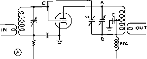 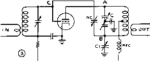 L с © О RFC О Г о jo OUT Figure 10 COMMON NEUTRALIZING CIRCUITS FOR SINGLE-ENDED AMPLIFIERS a split-stator plate capacitor makes the electrical balance of the circuit substantially independent of the mutual coupling within the coil and also makes the balance independent of the place where the coil is tapped. With conventional tubes this circuit will allow one neutralization adjustment to be made on, say, 28 Mc, and this adjustment usually will hold sufficiently close for operation on all lower frequency bands. Condenser Ci is used to balance out the plate-filament capacity of the tube to allow a perfect neutralizing balance at all frequencies. The equivalent bridge circuit is shown in figure IIB. If the plate-filament capacity of the tube is extremely low (lOOTH triode, for example), condenser Cj may be omitted, or may merely consist of the residual capacity of NC to ground. Grid Neutralization A split grid tank circuit may also be used for neutralization of a triode tube as shown in figure IOC. Out of phase voltage is developed across a balanced grid circuit, and coupled through NC to the single-ended plate circuit of the tube. The equivalent bridge circuit is shown in figure lie. This circuit is in balance until the stage is in operation when the loading effect of the tube upon one-half of the grid circuit throws the bridge circuit out of balance. The amount of unbalance depends upon the grid-plate capacity of the tube, and the amount of mutual inductance between the two halves of the grid coil. If an r-f voltmeter is placed between point A and ground, and a second voltmeter placed between point В and ground the loading effect of the tube will be noticeable. When the tube is supplied excitation with no plate voltage, NC may be adjusted until the circuit is in balance. When plate voltage is applied to the stage, the voltage from point A to ground will decrease, and the voltage from point В to ground will increase, both in direct proportion to the amount of circuit unbalance. The use of this circuit is not recommended above 7 Mc, and it should be used below that frequency only with low internal capacity tubes. Push-Pull Two tubes of the same type Neutralization can be coimected for push-pull operation so as to obtain twice as much ouфut as that of a single tube. A push-pull amplifier, such as that shown in figure 12 also has an advantage in that the circuit can more easily be balanced than a single-tube r-f amplifier. The various inter-electrode capacitances and the neutralizing capacitors are connected in such a manner that the reactances on one side of the tuned circuits are exactly equal to those on the opposite side. For this reason, push-pull r-f amplifiers can be more easily neutralized in very-high-frequency transmitters; also, they usually remain in perfect neutralization when tuning the amplifier to different bands. The circuit shown in figure 12 is perhaps 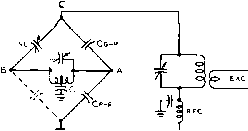 (A) BRIDGE EQUIVALENT OF FIGURE Ю-А 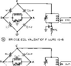 sidualn / fsMil I \ s (c) bridge EQUIVALENT OF FIGURE lO-C Figure 11 EQUIVALENT NEUTRALIZING CIRCUITS the most commonly used arrangement for a push-pull r-f amplifier stage. The rotor of the grid capacitor is grounded, and the rotor of the plate tank capacitor is by-passed to ground. Shunt or Call The feedback of energy from Neutralizotion grid to plate in an unneutral-ized r-f amplifier is a result of the grid-to-plate capacitance of the amplifier tube. A neutralization circuit is merely an electrical arrangement for nullifying the effect of this capacitance. All the previous neutralization circuits have made use of a bridge circuit for balancing out the grid-to-plate energy feedback by feeding back an equal amount of energy of opposite phase. Another method of eliminating the feedback effect of this capacitance, and hence of neutralizing the amplifier stage, is shown in figure 13- The grid-to-plate capacitance in the triode amplifier tube acts as a capacitive re- 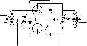 Figure 12 STANDARD CROSS-NEUTRALIZED PUSH-PULL TRIODE AMPLIFIER actance, coupling energy back from the plate to the grid circuit. If this capacitance is paralleled with an inductance having the same value of reactance of opposite sign, the reactance of one will cancel the reactance of the other and a high-impedance tuned circuit from grid to plate will result. This neutralization circuit can be used on ultra-high frequencies where other neutralization circuits are unsatisfactory. This is true because the lead length in the neutralization circuit is practically negligible. The circuit can also be used with push-pull r-f amplifiers. In this case, each tube will have its own neutralizing inductor connected from grid to plate. The main advantage of this arrangement is that it allows the use of single-ended tank circuits with a single-ended amplifier. The chief disadvantage of the shunt neutralized arrangement is that the stage must be re-neutralized each time the stage is retuned to a new frequency sufficiently removed that the grid and plate tank circuirs must be retuned to resonance. However, by the use of plug-in coils it is possible to change to a different band of operation by changing the neutralizing coil at the same time that the grid and plate coils are changed. The O.OOOl-ifd. capacitor in series with the neutralizing coil is merely a blocking capacitor to isolate the plate voltage from the grid circuit. The coil L will have to have a very large number of turns for the band of operation in order to be resonant with the comparatively small grid-to-plate capacitance. But since, in all ordinary cases with tubes operating on frequencies for which they were designed, the L/C ratio of the tuned circuit will be very high, the coil can use comparatively small wire, although it must be wound on air or very low loss dielectric and must be insulated for the sum of the plate r-f voltage and the grid r-f volrage. HANDBOOK Neutralizing Procedure 255 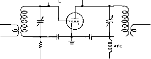 Figure 13 COIL NEUTRALIZED AMPLIFIER This neutralization circuit is very effective with triode tubes an any frequency, but is particularly effective in the v-h-f ronge. The coil L is adjusted so that it resonates at the operating frequency with the grid-to-plate capacitance of the tube. Capacitor С may be a very small unit of the low-capacitance neutraliiing type and is used to trim the circuit to resonance at the operating frequency. If some means of varying the inductance of the coil a small omount is available, the trimmer capacitor is not needed. grid excitation is applied, even though no primary a-c voltage is being fed to the plate transformer. A further check on the neutralization of any r-f amplifier can be made by noting whether maximum grid current on the stage comes at the same point of tuning on the plate tuning capacitor as minimum plate current. This check is made with plate voltage on the amplifier and with normal antenna coupling. As the plate tuning capacitor is detuned slightly from resonance on either side the grid current on the stage should decrease the same amount and without any sudden jumps on either side of resonance. This will be found to be a very precise indication of accurate neutralization in either a triode or beam-tetrode r-f amplifier stage, so long as the stage is feeding a load which presents a resistive impedance at the operating frequency. Push-pull circuits usually can be more completely neutralized than single-ended circuits at very high frequencies. In the intermediate range of from 3 to 15 Mc, single-ended circuits will give satisfactory results. 13-6 Neutralizing Procedure An r-f amplifier is neutralized to prevent self-oscillation or regeneration. A neon bulb, a flashlight lamp and loop of wire, or an r-f galvanometer can be used as a null indicator for neutralizing low-power stages. The plate voltage lead is disconnected from the r-f amplifier stage while it is being neutralized. Normal grid drive then is applied to the r-f stage, the neutralizing indicator is coupled to the plate coil, and the plate tuning capacitor is tuned to resonance. The neutralizing cacitor (or capacitors) then can be adjusted until minimum r.f. is indicated for resonant settings of both grid and plate tuning capacitors. Both neutralizing capacitors are adjusted simultaneously and to approximately the same value of capacitance when a physically symmetrical push-pull stage is being neutralized. A final check for neutralization should be made with a d-c milliammeter connected in the grid leak or grid-bias circuit. There will be no movement of the meter reading as the plate circuit is tuned through resonance (without plate voltage being applied) when the stage is completely neutralized. Plate voltage should be completely removed by actually opening the d-c plate circuit. If there is a d-c return through the plate supply, a small amount of plate current will flow when Neutralization of Radio-frequency amplifiers Screen-Grid R-F using screen-grid tubes can Amplifiers be operated without any ad- ditional provision for neutralization at frequencies up to about 15 Mc, provided adequate shielding has been provided between the input and output circuits. Special v-h-f screen-grid and beam tetrode tubes such as the 2E26, 807W, and 5516 in the low-power category and HK-257B, 4E27/8001, 4-125A, and 4-250A in the medium-power category can frequently be operated at frequencies as high as 100 Mc. without any additional provision for neutralization. Tubes such as the 807, 2E22, HY-69, and 813 can be operated with good circuit design at frequencies up to 30 Mc. without any additional provision for neutralization. The 815 tube has been found to require neutralization in many cases above 20 Mc, although the 829B tube will operate quite stably at 100 Mc. without neutralization. None of these tubes, however, has perfect shielding between the grid and the plate, a condition brought about by the inherent inductance of the screen leads within the tube itself. In addition, unless watertight shielding is used between the grid and plate circuits of the tube a certain amount of external leakage between the two circuits is present. These difficulties may not be serious enough to require neutralization of the stage to prevent oscillation, but in many instances they show up in terms of key-clicks when the stage in question is keyed, or as parasitics when the stage is modulated. Unless the designer of the equipment can carefully check the tetrode 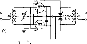 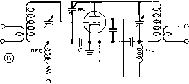 6 6 6 -hv +sg +hv 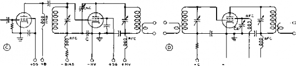 6 6 6 hv +sg +hv 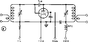 Figure 14 NEUTRALIZING CIRCUITS FOR BEAM TETRODES A convenfiona/ cross neutra/izec/ circuit for use with push-pull beam tetrodes is shown ot (A). The neutralizing capacitors (NC) usually consist of small plates or rods mounted alongside the plate e/ements of the tubes, (B) and (C) show grid neutralized circuits for use with a single-ended tetrode stage having either link coupling or capacitive coupling into the grid tank, (D) shows a method of tuning the screen-lead inductance to accomplish neutralization in a single-freguency v-h-f tetrode amplifier, while (E) shows a method of neutralization by increasing the grid-to-plate capacitance an a tetrode when the operating frequency is higher than that frequency where the tetrode is self-neutralized as a result of series resonance In the screen lead. Methods (D) and (E) normally are not practicable at frequencies below about 50 Mc. with the usual types of beam tetrode tubes. Stage for miscellaneous feedback between the grid and plate circuits, and make the necessary circuit revisions to reduce this feedback to an absolute minimum, it ts wise to neutral-ize the tetrode just as if it were a triode tube. In most push-pull tetrode amplifiers the simplest method of accomplishing neutralization is to use the cross-neutralized capacitance bridge arrangement as normally employed with triode tubes. The neutralizing capacitances, however, must be very much smaller than used with triode tubes, values of the order of 0.2 /i/;tfd. normally being required with beam tetrode tubes. This order of capacitance is far less than can be obtained with a conventional neutralizing capacitor at minimum setting, so the neutralizing arrangement is most commonly made especially for the case at hand. Most common procedure is to bring a conductor (connected to the opposite grid) in the vicinity of the plate itself or of rhe plate tuning cacitor of one of the tubes. Either one or two such capacitors may be used, two being normally used on a higher frequency amplifier in order to maintain balance within the stage. An example of this is shown in figure I4A. HANDBOOK Tetrode Neutralization 257 Neutralizing A single-ended tetrode r-f am-Single-Ended plifier Stage may be neutral-Tetrode Stages ized in the same manner as illustrated for a push-pull stage in figure 14A, provided a split-stator tank capacitor is in use in the plate circuit. However, in the majority of single-ended tetrode r-f amplifier stages a single-section capacitor is used in the plate tank. Hence, other neutralization procedures must be employed when neutralization is found necessary. The circuit shown in figure 14B is not a true neutralizing circuit, in that the plate-to-grid capacitance is not balanced out. However, the circuit can afford the equivalent effect by isolating the high resonant impedance of the grid tank circuit from the energy fed back from plate to grid. When NC and С are adjusted to bear the following ratio to the grid-to-plate capacitance and the total capacitance from grid-to-ground in the output tube: NC С gk both ends of the grid tank circuit will be at the same voltage with respect to groundas a result of r-f energy fed back to the grid circuit. This means that the impedance from grid to ground will be effectively equal to the reactance of the grid-to-cathode capacitance in parallel with the stray grid-to-ground capacitance, since the high resonant impedance of the tuned circuit in the grid has been effectively isolated from the feedback path. It is important to note that the effective grid-to-ground capacitance of the tube being neutralized includes the rated grid-to-cathode or input capacitance of the tube, the capacitance of the socket, wiring capacitances and other strays, but it does not include the capacitances associated with the grid tuning cacitor. Also, if the tube is being excited by capacitive coupling from a preceding stage (as in figure 14C), the effective grid-to-ground capacitance includes the output capacitance of the preceding stage and its associated socket and wiring capacitances. Cancellation of The provisions discussed in Screen-Lead the previous paragraphs are Inductance forneutralization of the small, though still important at the higher frequencies, grid-to-plate capacitance of beam-teaode tubes. However, in the vicinity of the upper-frequency limit of each tube type the inductance of the screen lead of the tube becomes of considerable importance. With a tube operating at a frequency where the inductance of the screen lead is appreciable, the screen will allow a considerable amount of energy leak-through from plate to grid even though the socket terminal on the tube is carefully by-passed to ground. This condition takes place even though the socket pin is bypassed since the reactance of the screen lead will allow a moderate amount of r-f potential to appear on the screen itself inside the electrode assembly in the tube. This effect has been reduced to a very low amount in such tubes as the Hytron 5516, and the Eimac 4X150A and 4X500A but it is still quite appreciable in most beam-tetrode tubes. The effect of screen-lead inductance on the stability of a stage can be eliminated at any particular frequency by one of two methods. These methods are: (1) Tuning out the screen-lead inductance by series resonatingthe screen lead inductance with a capacitor to ground. This method is illustrated in figure 14D and is commonly employed in commercially-built equipment for operation on a narrow frequency band in the range above about 75 Mc. The other method (2) is illustrated in figure 14E and consists in feeding back additional energy from plate to grid by means of a small capacitor connected between these two elements. Note that this capacitor is connected in such a manner as to increase the effective grid-to-plate capacitance of the tube. This method has been found to be effective with 807 tubes in the range above 50 Mc. and with tubes such as the 4-125A and 4-250A in the vicinity of their upper frequency limits. Note that both these methods of stabilizing a beam-tetrode v-h-f amplifier stage by cancellation of screen-lead inductance are suitable only for operation over a relatively narrow band of frequencies in the v-h-f range. At lower frequencies both these expedients for reducing the effects of screen-lead inductance will tend to increase the tendency toward oscillation of the amplifier stage. Neutralizing When a stage cannot be corn-Problems pletely neutralized, the difficulty usually can be traced to one or more of the following causes: (1) Filament leads not by-passed to the common ground of that particular stage. (2) Ground lead from the rotor connection of the split-stator tuning capacitor to filament open or too long. (3) Neutralizing capacitors in a field of excessive r.f. from one of the tuning coils. (4) Electromagnetic coupling between grid and plate coils, or between plate and preceding buffer or oscillator circuits. (5) Insufficient shielding or spacing between stages, or between grid and plate circuits in compact transmitters. (6) Shielding placed too close to plate circuit coils, causing induced currents in the shields. (7) Parasitic oscillations when plate voltage is applied. The cure for the latter is mainly a matter of cut and try-rearrange the parts. GBID LEAK  7Г interwouno coils-cunity coupling) 7Г .ooa:=p Figure 15 GROUNDED-GRID AMPLIFIER This fype of friode amplifier requires no neutralization, but can be used only with tubes having a relatively law plate-to-cathode capacitance change the length of grid or plate or neutralizing leads, insert a parasitic choke in the grid lead or leads, or eliminate the grid r-f chokes which may be the cause of a low-frequency parasitic (in conjunction with plate r-f chokes). 13-7 Grounded Grid Amplifiers Certain triodes have a grid configuration and lead arrangement which results in very low plate to filament capacitance when the control grid is grounded, the grid acting as an effective shield much in the manner of the screen in a screen-grid tube. By connecting such a triode in the circuit of figure 15, taking the usual precautions against stray capacitive and inductive coupling between input and output leads and components, a stable power amplifier is realized which requires no neutralization. At ultra-high frequencies, where it is difficult to obtain satisfactory neutralization with conventional triode circuits (particularly when a wide band of frequencies is to be covered), the grounded-grid arrangement is about the only practicable means of employing a triode amplifier. Because of the large amount of degeneration inherent in the circuit, considerably more excitation is required than if the same tube were employed in a conventional grounded-cathode circuit. The additional power required to drive a triode in a grounded-grid amplifier is not lost, however, as it shows up in the output circuit and adds to the power delivered to the load. But nevertheless it means that a larger driver stage is required for an amplifier of 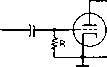 о Figure 16 CONVENTIONAL TRIODE FREQUENCY MULTIPLIER Small triodes such as the 6C4 operate satisfactorily as frequency multipliers, and can deliver output well into the v-h-f range. Resistor R normally will have a value in the vicinity of 100,000 ohms. given output, because a moderate amouiit of power is delivered to the amplifier load by the driver stage of a grounded-grid amplifier. 13-8 Frequency Multipliers Quartz crystals and variable-frequency oscillators are not ordinarily used for direct control of the output of high-frequency transmitters. Frequency multipliers are usually employed to multiply the frequency to the desired value. These multipliers operate on exact multiples of the excitation frequency; a З-б-Мс. crystal oscillator can be made to control the output of a transmitter on 7.2 or 14.4 Mc, or on 28.8 Mc.,by means of one or more frequency multipliers. Uhen used at twice frequency, they are often termed frequency doublers. A simple doubler circuit is shown in figure 16. It consists of a vacuum tube with its plate circuit tuned to twice the frequency of the grid driving circuit. This doubler can be excited from a crystal oscillator or another multiplier or amplifier stage. Doubling is best accomplished by operating the tube with high grid bias. The grid circuit is driven approximately to the normal value of d-c grid current through the r-f choke and grid-leak resistor, shown in figure 16. The resistance value generally is from two to five times as high as that used with the same tube for straight amplification. Consequently, the grid bias is several times as high for the same value of grid current. Neutralization is seldom necessary in a doubler circuit, since the plate is tuned to twice the frequency of the grid circuit. The impedance of the grid driving circuit is very low at the doubling frequency, and thus there is little tendency for self-excited oscillation. HANDBOOK Frequency Multipliers 259 © \C2J C1  о о -о о о Е TANK CIRCUrT OUTPUT VOLTAGE 1(CUTOFF) АЛЛ (\ Г\ Л A Cl ffiCl ij Ц M 0 5 U\ W Y \ , ( N (CUTOFF)------i---p4------L---- * - EXCITATION \ / VOLTAGE  о о Figure 17 FREQUENCY MULTIPLIER CIRCUITS The output of о triode v-h-f frequency multiplier often may be increased by neutralization of the grid-to-plate capacitance as shown at (A) above. Such a stage also may be operated as a straight amplifier when the occasion demands. A pentode frequency multiplier is shown at (B). Conventional power tetrodes operate satisfactorily as multipliers so long as the output frequency is below about WO Mc. Above this frequency special v-h-f tetrodes must be used to obtain satisfactory output. Frequency doublets require bias of several times cutoff; high-p tubes therefore are desirable for this type of service. Tubes which have amplification factors from 20 to 200 are suitable for doubler circuits. Tetrodes and pentodes make excellent doublets. Lov-fi triodes, having amplification constants of from 3 to 10, are not applicable for doubler service. In extreme cases the grid voltage must be as high as the plate voltage for efficient doubling action. Angle of Flow The angle of plate current flow in Frequency in a frequency multiplier is a Multipliers very important factor in determining the efficiency. As the angle of flow is decreased for a given value of grid current, the efficiency increases. To reduce the angle of flow, higher grid bias is required so that the grid excitation voltage will exceed the cutoff value for a shorter portion of the exciting-voltage cycle. For a high order of efficiency, frequency doubiers should have an angle of flow of 90 degrees or less, triplers 60 degrees or less, and quadruplers Figure 18 ILLUSTRATING THE ACTION OF A FREQUENCY DOUBLER 45 degrees or less. Under these conditions the efficiency will be on the same order as the reciprocal of the harmonic on which the stage operates. In other words the efficiency of a doubler will be approximately Уг or 50 pet cent, the efficiency of a tripler will be approximately % or 33 per cent and that of a quadruplet will be about 25 per cent. With good stage design the efficiency can be somewhat greater than these values, but as the angle of flow is made greater than these limiting values, the efficiency falls off rapidly. The reason is apparent from a study of figure 18. The pulses ABC, EFG, JKL illustrate 180-degree excitation pulses under Class В operation, the solid straight line indicating cutoff bias. If the bias is increased by N times, to the value indicated by the dotted straight line, and the excitation increased until the peak r-f voltage with respect to ground is the same as before, then the excitation frequency can be cut in half and the effective excitation pulses will have almost the same shape as before. The only difference is that every other pulse is missing; MNO simply shows where the missing pulse would go. However, if the Q of the plate tank circuit is high, it will have sufficient flywheel effect to carry over through the missing pulse, and the only effect will be that the plate input and r-f output at optimum loading drop to approximately half. As the input frequency is half the output frequency, an efficient frequency doubler is the result. By the same token, a tripler or quadnipler can be analyzed, the tripler skipping two excitation pulses and the quadruplet three. In each case the excitation pulse ideally should be short enough that it does not exceed 180 degrees at the output frequency; otherwise the excitation actually is bucking the output over a portion of the cycle. In actual practice, it is found uneconomical to provide sufficient excitation to run a tripler or quadrupler in this fashion. Usually the ex- 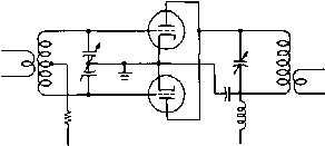 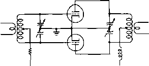 Figure 19 PUSH-PUSH FREQUENCY DOUBLER The output of a doubler stage may be materially increased through the use of a push-push circuit such as illustrated obove. citation pulses will be at least 90 degrees at the exciting frequency, with correspondingly low efficiency, but it is more practicable to accept the low efficiency and build up the output in succeeding amplifier stages. The efficiency can become quire low before the power gain becomes less than unity. Pusb-Push Two tubes can be connected in Multipliers parallel to give twice the output of a single-tube doubler. If the grids are driven out of phase instead of ш phase, the tubes then no longer work simultaneously, but rather one at a time. The effect is to fill in the missing pulses (figure 18). Not only is the output doubled, but several advantages accrue which cannot be obtained by straight parallel operation. Chief among these is the effective neutralization of the fundamental and all o(/(/harmonics, an advantage when spurious emissions must be minimized. Another advantage is that when the available excitation is low and excitation pulses exceed 90 degrees, the output and efficiency will be greater than for the same tubes connected in parallel. The same arrangement may be used as a quadrupler, with considerably better efficiency than for straight parallel operation, because seldom is it practicable to supply sufficient excitation to permit 45 degree excitation pulses. As pointed out above, the push-push arrangement exhibits better efficiency than a single ended multiplier when excitation is inadequate for ideal multiplier operation. A typical push-push doubler is illustrated in figure 19. When high transconductance tubes are employed, it is necessary to employ a split-stator grid tank capacitor to prevent self oscillation; with well screened tetrodes or pentodes having medium values of transconductance, a split-coil arrangement with a single-section capacitor may be employed (the Figure 20 PUSH-PULL FREQUENCY TRIPLER The push-pull tripler Is advantageous in the v-h-f range since circuit balance is maintained both in the input and output circuits. If the circuit is neutralized it may be used either as a straight amplifier or as a tripler. Either triodes or tetrodes may be used; dual-unit tetrodes such as the 815, 832A, and 829B are particularly effective in the v-h-f range. center tap of the grid coil being by-passed to ground). Push-Pull Frequency It is frequently desirable Triplers in the case of u-h-f and v-h-f transmirters that frequency multiplication stages be balanced with respect to ground. Further it is just as easy in most cases to multiply the crystal or v-f-o frequency by powers of three rather than multiplying by powers of two as is frequently done on lower frequency transmitters. Hence the use of push-pull triplers has become quite prevalenr in both commercial and amateur v-h-f and u-h-f transmitter designs. Such stages are balanced with respect to ground and appear in construction and on paper essentially the same as a push-pull r-f amplifier stage with the exception that the output tank circuit is tuned to three times the frequency of the grid tank circuit. A circuit for a push-pull tripler stage is shown in figure 20. A push-pull tripler stage has the further advantage in amateur work that it can also be used as a conventional push-pull r-f amplifier merely by changing the grid and plate coils so that they tune to the same frequency. This is of some advantage in the case of operating the 50-Mc. band with 50-Mc. excitation, and then changing the plate coil to tune to 144 Mc. for operation of the stage as a tripler from excisation on 48 Mc. This circuit arrangement is excellent for operation with push-pull beam tetrodes such as the 6360 and 829B, although a pair of tubes such as the2E26, or 5763 could just as well be used if proper attention were given to the matter of screen-lead inductance. 1 ... 22 23 24 25 26 27 28 ... 80 |
|
© 2026 AutoElektrix.ru
Частичное копирование материалов разрешено при условии активной ссылки |