 |
 |
 |
| Главная Журналы Популярное Audi - почему их так назвали? Как появилась марка Bmw? Откуда появился Lexus? Достижения и устремления Mercedes-Benz Первые модели Chevrolet Электромобиль Nissan Leaf |
Главная » Журналы » Simple coaxial reflectometer 1 ... 23 24 25 26 27 28 29 ... 80 HANDBOOK Tank Circuits 13-9 Tank Circuit Capacitances It is necessary that the proper value of Q be used in the plate tank circuit of any r-f amplifier. The following section has been devoted to a treatment of the subject, and charts are given to assist the reader in the determination of the proper L/C ratio to be used in a radio-frequency amplifier stage. A Class С amplifier draws plate current in the form of very distorted pulses of short duration. Such an amplifier is always operated into a tuned inductance-capacitance or tank circuit which tends to smooth out these pulses, by its storage or tank action, into a sine wave of radio-frequency output. Any wave-form distortion of the carrier frequency results in harmonic interference in higher-frequency channels. A Class A r-f amplifier would produce a sine wave of radio-frequency output if its exciting waveform were also a sine wave. However, a Class A amplifier stage converts its d-c input to r-f output by acting as a variable resistance, and therefore heats considerably. A Class С amplifier when driven hard with short pulses at the peak of the exciting waveform acts more as an electronic switch, and therefore can convert its d-c input to r-f output with relatively good efficiency. Values of plate circuit efficiency from 65 to 85 per cent are common in Class С amplifiers operating under optimum conditions of excitation, grid bias, and loading. Tank Circuit Q As Stated before, the tank circuit of a Class С amplifier receives energy in the form of short pulses of plate current which flow in the amplifier tube. But the tank circuit must be able to store enough energy so that it can deliver a current essentially sine wave in form to the load. The ability of a tank to store energy in this manner may be designated as the effective Q of the tank circuit. The effective circuit Q may be stated in any of several ways, but essentially the Q of a tank circuit is the ratio of the energy stored to 2n times the energy lost per cycle. Further, the energy lost per cycle must, by definition, be equal to the energy delivered to the tank circuit by the Class С amplifier tube or tubes. TheQ of a tank circuit at resonance is equal to its parallel resonant impedance (the resonant impedance is resistive at resonance) divided by the reactance of either the capacitor or the inductor which go to make up the tank. The inductive reactance is equal to the capacitive reactance, by definition, at resonance. Hence we may state: DYNAMIC CHARACTERISTIC   14 fill GAIO SWING Figure 21 CLASS С AMPLIFIER OPERATION Plate current pulses are shown at (A), (B), and (C). The dip in the top of the plate current waveform will occur when the excitation voltage is such that the minimum plate voltage dips befotv the maximum grid voltage. A detailed discussion of the operation of Class С amplifiers is given in Chapter Seven. where Rl is the resonant impedance of the tank and is the reactance of the tank capacitor and Xl is the reactance of the tank coil. This value of resonant impedance, Rl, is the load which is presented to the Class С amplifier tube in a single-ended circuit such as shown in figure 21. The value of load impedance, Rl, which the Class С amplifier tube sees may be obtained, looking in the other direction from the tank coil, from a knowledge of the operating conditions on the Class С tube. This load impedance may be obtained from the following expression, which is true in the general case of any Class С amplifier: Ri = F 2 p m 2 Np lb Ebb where the values in the equation have the characteristics listed in the beginning of Chapter 6. The expression above is academic, since the peak value of the fundamental component of plate voltage swing, Ep is not ordinarily known unless a high-voltage peak a-c voltmeter is available for checking. Also, the decimal value of plate circuit efficiency is not ordinarily known with any degree of accuracy. However, in a normally operated Class С amplifier 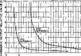 10 15 20 TANK CIRCUIT Q Figure 22 RELATIVE HARMONIC OUTPUT PLOTTED AGAINST TANK CIRCUIT Q the plate voltage swing will be approximately equal to 0.85 to 0.9 times the d-c plate voltage on the stage, and the plate circuit efficiency will be from 70 to 80 per cent (Np of 0.7 to 0.8), the higher values of efficiency normally being associated with the higher values of plate voltage swing. With these two assumptions as to the normal Class С amplifier, the expression for the plate load impedance can be greatly simplified to the following approximate but useful expression: Rd.c. which means simply that the resistance presented by the tank circuit to the Class С tube is approximately equal to one-half the d-c load resistance which the Class С stage presents to the power supply (and also to the modulator in case high-level modulation of the stage is to be used). Combining the above simplified expression for the r-f impedance presented by the tank to the tube, with the expression for tank Q given in a previous paragraph we have the following expression which relates the reactance of the tank capacitor or coil to the d-c input to the Class С stage: Xc = Xlc The above expression is the basis of the usual charts giving tank capacitance for the various bands in terms of the d-c plate voltage and current to the Class С stage, including the charts of figure 23, figure 24 and figure 25. Harmonic Radiation vs. Q The problem of harmonic radiation from transmitters has long been present, but it has become critical only relatively recently along with the extensive occupation of the v-h-f range. Television signals are particularly susceptible to interference from other signals falling within the pass band of the receiver, so that the TVI problem has received the major emphasis of all the services in the v-h-f range which are susceptible to interference from harmonics of signals in the h-f or lower v-h-f range. 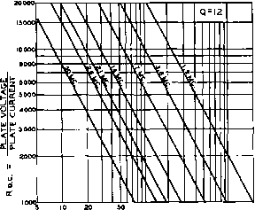 100 200 500 1000 2000 TOTAL CAPACITANCE ACROSS LC CIRCUIT (Cl) ®  /Г о о © -с 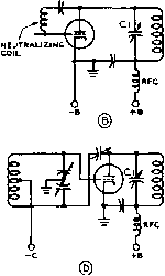 Figure 23 PLATE-TANK CIRCUIT ARRANGEMENTS Shown above In the case of each of the tonik circuit types is the recommended tank circuit capacitance, (A) is a conventionof tetrode amplifier, (В) is о coil-neutralized triode amplifier, (C) is a grounded-grid triode amplifier, (D) is a grid-neutralized triode amplifier. HANDBOOK Tank Circuits 263 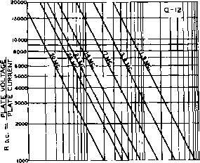 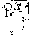 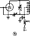 1 г 3 5 7 10 20 30 m 100 200 300 1000 CORRECT VALUES OF TANK CIRCUIT CAPACITANCE (C) FOR OPERATING Q OF 12 WITH StNGLE-ENDEO SPLIT TANK COILS Figure 24 PLATE-TANK CIRCUIT ARRANGEMENTS £hown above for eacb of the tank circuit types is fbe recommen</e</ tonic circuH capacitance at the operating frequency for on operating Q of 12. (A) is о split-stotor tank, each section of which is twice the capacity value read on the graph. (B) is circuit using tapped call for phase reversal. Inspection of figure 22 will show quickly that the tank circuit of a Class С amplifier should have.an operating Q of 12 or greater to afford satisfactory rejection of second harmonic energy. The curve begins to straighten out above a Q of about 15, so that a considerable increase in Q must be made before an appreciable reduction in second-harmonic energy is obtained. Above a circuit Q of about 10 any increase will not afford appreciable reduction in the third-harmonic energy, so that additional harmonic filtering circuits external to the amplifier proper must be used if increased attenuation of higher order harmonics is desired. The curves also show that push-pull amplifiers may be operated at Q values of 6 or so, since the second harmonic is cancelled to a large extent if there is no unbalanced coupling between the output tank circuit and the antenna system. Capacity Charts for Correct Tank Q Figures 23, 24 and 25 illustrate the correct value of tank capacity for various circuit configurations. A Q value of 12 has been chosen as optimum for single ended circuits, and a value of 6 has been chosen for push-pull circuits. Figure 23 is used when a single ended stage is employed, and the capacitance values given are for the total capacitance across the tank coil. This value includes the tube interelectrode capacitance (plate to ground), coil distributed capacitance, wiring capacities, and the value of any low- inductance plate-to-ground by-pass capacitor as used for reducing harmonic generation, in addition to the actual in-use capacitance of the plate tuning capacitor. Total circuit stray capacitance may vary from perhaps 5 micromicrofarads for a v-h-f stage to 30 micro-microfarads for a medium power tetrode h-f stage. When a split plate tank coil is employed in the stage in question, the graph of figure 24 should be used. The capacity read from the graph is the total capacity across the tank coil. If the split-stator tuning capacitor is used, each section of the capacitor should have a value of capacity equal to twice the value indicated by the graph. As in the case of figure 23, the values of capacity read on the graph of figure 24 include all residual circuit capacities. For push-pull operation, the correct values of tank circuit capacity may be determined with the aid of figure 25. The capacity values obtained from figure 25 are the effective values across the tank circuit, and if a split-stator tuning capacitor is used, each section of the capacitor should have a value of capacity e-qual to twice the value indicated by the graph. As in the case of figures 23 and 24, the values of capacity read on the graph of figure 25 include all residual circuit capacities. The tank circuit operates in the same manner whether the tube feeding it is a pentode, beam tetrode, neutralized triode, grounded-grid triode, whether it is single ended or push- 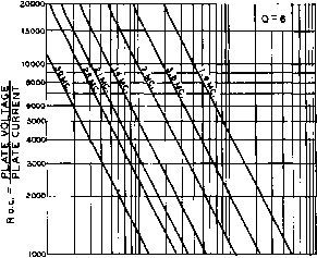 ® ® I 2 3 5 7 10 20 30 so 100 200 5O0 1000 CORRECT VALUES OF TANK CIRCUIT CAPACITANCE (Cl) FOR OPERATING Q OF 6 WITH PUSH-PULL TANK CIRCUITS RFC 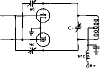 Figure 25 PLATE-TANK CIRCUIT ARRANGEMENTS FOR PUSH-PULL STAGES Shown above is recommended tank circuit capacity at operating frequency for a Q of 6, (A) Ig split-stator tank, each section of which is twice the capacity value read on the graph. (B) is circuit using tapped coil for phase reversal. pull, or whether it is shunt fed or series fed. The important thing in establishing the operating Q of the tank circuit is the ratio of the loaded resonant impedance across its terminals to the reactance of the L and the С which make up the tank. Due to the unknowns involved in determining circuit stray capacitances it is sometimes more convenient to determine the value of L required for the proper circuitQ (by the method discussed earlier in this Section) and then to vary the tuned circuit capacitance until resonance is reached. This method is most frequently used in obtaining proper circuit Q in commercial transmitters. The values of Rp for using the charts are easily calculated by dividing the d-c plate supply voltage by the total d-c plate current (expressed in amperes). Correct values of total tuning capacitance are shown in the chart for the different amateur bands. The shunt stray capacitance can be estimated closely enough for all practical purposes. The coil inductance should then be chosen which will produce resonance at the desired frequency with the total calculated tuning capacitance. Effect of Load- The Q of a circuit depends ing on Q upon the resistance in series with the capacitance and inductance. This series resistance is very low for a low-loss coil not loaded by an antenna circuit. The value of Q may be from 100 to 600 under these conditions. Coupling an antenna circuit has the effect of increasing the series resistance, though in this case the power is consumed as useful radiation by the antenna. Mathematically, the antenna increases the value of R in the expression Q = coh/R where L is the coil inductance in microhenrys and CO is the term 2n-f, f being in megacycles. The coupling from the final tank circuit to the antenna or antenna transmission line can be varied to obtain values of Q from perhaps 3 at maximum coupling to a value of Q equal to the unloaded Q of the circuit at zero antenna coupling. This value of unloaded Q can be as high as 500 or 600, as mentioned in the preceding paragraph. However, the value of Q = 12 will not be obtained at values of normal d-c plate current in the Class С amplifier stage unless the C-to-L ratio in the tank circuit is correct for that frequency of operation. Tuning Capacitor To determine the required Air Gap tuning capacitor air gap for a particular amplifier circuit it is first necessary to estimate the peak r-f voltage which will appear between the plates of the tuning capacitor. Then, using figure 26, it is possible to estimate the plate spacing which will be required. The instantaneous r-f voltage in the plate circuit of a Class С amplifier tube varies from nearly zero to nearly twice the d-c plate voltage. If the d-c voltage is being 100 per cent modulated by an audio voltage, the r-f peaks will reach nearly four times the d-c voltage. FIGURE 26 USUAL BREAKDOWN RATINGS OF COMMON PLATE SPACINGS Air-gap in Peak voltage inches breokdown 030 . ..... ...... 1,000 .050 . ..... ......... .......... 2,000 .070 ................... ....... 3,000 .100 ....... ....... 4,000 .125 ..... 4,500 ISO ... ..... ..... 5,200 .170 ................................. 6,000 .200 ..... ...... ..... . 7,500 .250 . . . ..... 9,000 .350 -------- --------- ------...... 11,000 .500 ................................. 15,000 .700 .................. ...... 20,000 Recommended air~gap for use when no d-c voltage appears across plate tank condenser (when plate circuit is shunt fed, or when the plate tank condenser is insulated from ground).
Spacings should be multiplied by 7.5 far same safety factor when d-c voltage appears across plate tank condenser. These rules apply to a loaded amplifier or buffer stage. If either is operated without an r-f load, the peak voltages will be greater and can exceed the d-c plate supply voltage. For this reason no amplifier should be operated without load when anywhere near normal d-c plate voltage is applied. If a plate blocking condenser is used, it must be rated to withstand the d-c plate voltage plus any audio voltage. This capacitor should be rated at a d-c working voltage of at least twice the d-c plate supply in a plate modulated amplifier, and at least equal to the d-c supply in any other type of r-f amplifier. 13-10 L and Pi Matching Networks The L and pi networks often can be put to advantageous use in accomplishing an impedance match between two differing impedances. Common applications are the matching between a transmission line and an antenna, or between the plate circuit of a single-ended amplifier stage and an antenna transmission line. Such networks may be used to accomplish a match 2J Rp RPRa(Q2-1-1) f exact) Rp = q2 Ra (approx.) n- Xl Xc ,Rp . Rp Ra Ra Xc Xl XlXc Rp= 225 Ra for operatinc circuit< q of 15: Xc = - Лр. 15 Figure 27 THE L NETWORK IMPEDANCE TRANSFORMER The L network is useful with a moderate operating Q for high values of impedance transformation, and it may be used for applications other than in the plate circuit of a tube with relatively low values of operating Q for moderate impedance transformations. Exact and approximate design equations are given. between the plate tank circuit of an amplifier and a transmission line, or they may be used to match directly from the plate circuit of an amplifier to the line without the requirement for a tank circuit-provided the network is designed in such a manner that it has sufficient operating Q for accomplishing harmonic attenuation. The L Matching The L network is of limited Network utility in impedance match- ing since its ratio of impedance transformation is fixed at a value equal to (Q+1). The operating Q may be relatively low (perhaps 3 to 6) in a matching network between the plate tank circuit of an amplifier and a transmission line; hence impedance transformation ratios of 10 to 1 and even lower may be attained. But when the network also acts as the plate tank circuit of the amplifier stage, as in figure 27, the operating Q should be at least 12 and preferably 15- An operating Q of 15 represents an impedance transformation of 225; this value normally will be too high even for transforming from the 2000 to 10,000 ohm plate impedance of a Class С amplifier stage down to a 50-ohm transmission line. However, the L network is interesting since it forms the basis of design for the pi network. Inspection of figure 27 will show that the L network in reality must be considered as a parallel-resonant tank circuit in which Кд represents the coupled-in load resistance; only in this case the load resistance is directly coupled into the tank circuit rather than being inductively coupled as in the conven- Ro.c. Rp TP Cl I~ L TOTAL -t-вСЕЬЬ) R0.c,= -f - /ra(q +0-Rp EfL Ra2H-XC2 Ltot. = Xli + L2 Figure 28 THE PI NETWORK The pi networfc is valuable for use os on impedance transformer over a wide rafio of transformation values. The operating 0 should be at least 72 and preferably IS to 20 when the circuit is to be used in the plate circuit of a Class С amplifier. Design equations are given above. The inductor Lfot represents a single inductance, usually variable, with a value equal to the sum of Li and L. tional arrangement where the load circuit is coupled to the tank circuit by means of a link. When Ra is shorted, L and С comprise a conventional parallel-resonant tank circuit, since for proper operation L and С must be resonant in order for the network to present a resistive load to the Class С amplifier. The Pi Network The pi impedance matching network, illustrated in figure 28, is much more general in its application than the L network since it offers greater harmonic attenuation, and since it can he used to match a relatively wide range of impedances while still maintaining any desired operating Q. The values of C, and L, io the pi network of figure 28 can be thought of as having the same values of the L network in figure 27 for the same operating Q, but what is more important from the comparison 8Гапфо1п1 these values will be the same as in a conventional tank circuit. The value of the capacitance may be determined by calculation, with the operating Q and the load impedance which should be reflected to the plate of the Class С amplifier as the two knowns-or the actual values of the ca- pacitance may be obtained for an operating Q of 12 by reference to figures 23, 24 and 25. The inductive arm in the pi network can be thought of as consisting of two inductances in series, as illustrated in figure 28. The first portion of this inductance, Li, is that value of inductance which would resonate with C, at the operating frequency-the same as in a conventional tank circuit. However, the actual value of inductance in this arm of the pi network, Ltot will be greater than Li for normal values of impedance transformation. For high transformation ratios Lt will be only slightly greater than L,; for a transformation ratio of 1.0, L,ot will be twice as great as L,. The amount of inductance which must be added to L, to restore resonance and maintain circuit Q is obtained through use of the expression for X j in figure 28. The peak voltage rating of the main tuning capacitor C, should be the normal value for a Class С amplifier operating at the plate voltage to be employed. The inductor Ltot may be a plug-in coil which is changed for each band of operation, or some sort of variable inductor may be used. A continuously variable slider-type of variable inductor, such as used in certain items of surplus military equipment, may be used to good advantage if available, or a tapped inductor such as used in the ART-13 may be employed. However, to maintain good circuit Q on the higher frequencies when a variable or tapped coil is used on the lower frequencies, the tapped or variable coil should be removed from the circuit and replaced by a smaller coil which has been especially designed for the higher frequency ranges. The peak voltage rating of the output or loading capacitor, Cj, is determined by the power level and the impedance to be fed. If a 50-ohm coaxial line is to be fed from the pi network, receiving-type capacitors will be satisfactory even up to the power level of a plate-modulated kilowatt amplifier. In any event, the peak voltage which will be impressed across the output capacitor is expressed by: Epk = 2 Ra Wq, where Epj is the peak voltage across the capacitor, Rg is the value of resistive load which the network is feeding, and Wq is the maximum value of the average power output of the stage. The harmonic attenuation of the pi network is quite good, although an external low-pass filter will be required to obtain harmonic attenuation value upward of 100 db such as normally required. The attenuation to second harmonic energy will be approximately 40 db for an operating Q of 15 for the pi network; the value increases to about 45 db for a 1:1 transformation and falls to about 38 db for an impedance step-down of 80:1, assuming that the operating Q is maintained at 15. HANDBOOK Grid Bias 267 о -t-b :rfci  TOOOIP- RFC2 7Г output f . 1УИЕКЕ E В /5 fiJt те vol та 6£ PLATE LOAD (ohms) , and I в is plate current <ixiB in /\прелв5. Cb- .ooozsjjf. mica capacitor rated at twice the d.c. plate voltage. RFCl -n гВ enameled, close-wound on a ceramic insulator roia., 1long or national r-I7SA RFC2.- Zj MH, national R-IOO
* Values given are approximations. All components shown in Table I are for a Q of 12. For other values of Q, use Q C. Q. It, - ~ - ond - =--When the estimated plate load is higher than 5,000 ohms, it is recommended that the Qii C Q .L, components be selected for о circuit Q between 20 and 30. Table I Components for Pi-Coupled Final Amplifiers Component Chart To simplify design pro-for Pi-Networks cedure, a pi-network chart, compiled by M. Seybold, W2RYI (reproduced by courtesy of R.C.A. Tube Division, Harrison, N.J.) is shown in table I. This chart summarizes the calculations of figure 28 for various values of plate load. 13-11 Grid Bias Radio-frequency amplifiers require some form of grid bias for proper operation. Practically all r-f amplifiers operate in such a manner that plate current flows in the form of short pulses which have a duration of only a fraction of an r-f cycle. To accomplish this with a sinusoidal excitation voltage, the operating grid bias must be at least sufficient to cut off the plate current. In very high efficiency Class С amplifiers the operating bias may be many times the cutoff value. Cutoff bias, it will be recalled, is that value of grid voltage which will reduce the plate current to zero at the plate voltage employed. The method for calculating it has been indicated previously. This theoretical value of cutoff will not reduce the plate current completely to zero, due to the variable-/ tendency or knee which is characteristic of all tubes as the cutoff point is approached. Class С Bias Amplitude modulated Class С amplifiers should be operated with the grid bias adjusted to a value greater than twice cutoff at the operating plate volt- 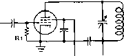 prfow DRIVER Figure 29 GRID-LEAK BIAS The grid leak on on amplifier or multiplier stage may also be used as the shunt feed impedance to the grid of the tube when a high value of grid leak (greater than perhaps 20,000 ohms) is used. When a lower value of grid leak is to be employed, an r.f choke should be used between the grid of the tube and the grid leak to reduce r-f lasses in the grid leak resistance. age. This procedure will insure that the tube is operating at a bias greater than cutoff when the plate voltage is doubled on positive modulation peaks. C-w telegraph and FM transmitters can be operated with bias as low as cutoff, if only limited excitation is available and moderate plate efficiency is satisfactory. In a c-w transmitter, the bias supply or resistor should be adjusted to the point which will allow normal grid current to flow for the particular amount of grid driving r-f power available. This form of adjustment will allow more output from the under-excited r-f amplifier than when higher bias is used with corresponding lower values of grid current. In any event, the operating bias should be set at as low a value as will give satisfactory operation, since harmonic generation in a stage increases rapidly as the bias is increased. Grid-Leak Bias A resistor can be connected in the grid circuit of a Class С amplifier to provide grid-leak bias. This resistor, R, in figure 29, is part of the d-c path in the grid circuit. The r-f excitation applied to the grid circuit of the tube causes a pulsating direct current to flow through the bias supply lead, due to the rectifying action of the grid, and any current flowing through R, produces a voltage drop across that resistor. The grid of the tube is positive for a short duration of each r-f cyclej and draws electrons from the filament cm: cathode of the tube during that time. These electrons complete the circuit through the d-c grid return. The voltage drop across the resistance in the grid return provides a negative bias for the grid. Grid-leak bias automatically adjusts itself over fairly wide variations of r-f excitation. The value of grid-leak resistance should be such that normal values of grid current will flow at the maximum available amount of r-f FROM ORIVER-  /Г о о о -BIAS SUPPLY Figure 30 COMBINATION GRID-LEAK AND FIXED BIAS Grid-leak bias often is used in conjunction with a fixed minimum value of power supply bias. This arrangement permits the operating bias to be established by the excitation energy, but in the absence of excitation the electrode currents to the tube will be held to safe values by the fixed-minimum power supply bias. If a relatively low value of grid leak is io be used, an r-f choke should be connected between the grid of the tube and the grid leak as discussed in figure 29, excitation. Grid-leak bias cannot be used for grid-modulated or linear amplifiers in which the average d-c grid current is constantly varying with modulation. Sofety Bias Grid-leak bias alone provides no protection against excessive plate current in case of failure of the source of r-f grid excitation. A C-battery or C-bias supply can be connected in series with the grid leak, as shown in figure 30. This fixed protective bias will protect the tube in the event of failure of grid excitation. Zero-bias tubes do not require this bias source in addition to the grid leak, since their plate current will drop to a safe value when the excitation is removed. Cofhode Bias A resistor can be connected in series with the cathode or center-tapped filament lead of an amplifier to secure automatic bias. The plate current flows through this resistor, then back to the cathode or filament, and the voltage drop across the resistor can be applied to the grid circuit by connecting the grid bias lead to the grounded or power supply end of the resistor R, as shown in figure 31. The grounded (B-minus) end of the cathode resistor is negative relative to the cathode by an amount equal to the voltage drop across the resistor. The value of resistance must be so chosen that the sum of the desired grid and plate current flowing through the resistor will bias the tube for proper operation. This type of bias is used more extensively in audio-frequency than in radio-frequency amplifiers. The voltage drop across the resistor  FROM DRIVER  BIAS -±r BATTERY - Figure 31 R-F STAGE WITH CATHODE BIAS Cathode bias sometimes is advantageous for use in an r-f stage that operates with a relatively small amount of r-f excitation. Figure 32 R-F STAGE WITH BATTERY BIAS Battery bias Is seldom used, due to deterioration of the cells by the reverse grid current. However, ii may be used in certain special applications, or the fixed bias voltage may be supplied by a bias power supply. must be subtracted from the total plate supply voltage when calculating the power input to the amplifier, and this loss of plate voltage in an r-f amplifier may be excessive. A Class A audio amplifier is biased only to approximately one-half cutoff, whereas an r-f amplifier may be biased to twice cutoff, or more, and thus the plate supply voltage loss may be a large percentage of the total available voltage when using low or medium jj. tubes. Oftentimes just enough cathode bias is employed in an r-f amplifier to act as safety bias to protect the tubes in case of excitation failure, with the rest of the bias coming from a grid leak. Separate Bias An external supply often is Supply used for grid bias, as shown in figure 32. Battery bias gives very good voltage regulation and is satisfactory for grid-modulated or linear amplifiers, which operate at low grid current. In the case of Class С amplifiers which operate with high grid current, battery bias is not satisfactory. This direct current has a charging effect on the dry batteries; after a few months of service the cells will become unstable, bloated, and noisy. A separate a-c operated power supply is commonly used for grid bias. The bleeder resistance across the output of the filter can be made sufficiently low in value that the grid current of the amplifier will not appreciably change the amount of negative grid-bias voltage. Alternately, a voltage regulated grid-bias supply can be used. This type of bias supply is used in Class В audio and Class В r-f linear amplifier service where the voltage regulation in the C-bias supply is important. For a Class С amplifier, regulation is not so important, and an economical design of components in the power supply, therefore, can be utilized. In this case, the bias voltage must be adjusted with normal grid current flowing, as the grid current will raise the bias con- siderably when it is flowing through the bias-supply bleeder resistance. 13-12 Protective Circuits for Tetrode Transmitting Tubes The tetrode transmitting tube requires three operating voltages: grid bias, screen voltage, and plate voltage. The current requirements of these three operating voltages are somewhat interdependent, and a change in potential of one voltage will affect the current drain of the tetrode in respect to the other two voltages. In particular, if the grid excitation voltage is interrupted as by keying action, or if the plate supply is momentarily interrupted, the resulting voltage or current surges in the screen circuit are apt to permanently damage the tube. The Series Screen Supply A simple method of obtaining screen voltage is by means of a dropping resistor from the high voltage plate supply, as shown in figure 33. Since the current drawn by the screen is a function of the exciting voltage applied to the tetrode, the screen voltage will rise to equal the plate voltage under conditions of no exciting voltage. If the control grid is overdriven, on the other hand, the screen current may become excessive. In either case, damage to the screen and its associated components may result. In addition, fluctuations in the plate loading of the tetrode stage will cause changes in the screen current of the tube. This will result in screen voltage fluctuations due to the inherently poor voltage regulation of the screen series dropping resistor. These effects become dangerous to tube life if the plate voltage is greater than the screen voltage by a factor of 2 or so.
DROPPING-RESISTOR SCREEN SUPPLY BIAS curs < OfF clamp] tube . 7Г о о о о о CLAMP TUBE The Clamp Tube A clamp tube may be added to the series screen supply, as shown in figure 34. The clamp tube is normally cut off by virtue of the d-c grid bias drop developed across the grid resistor of the tetrode tube. When excitation is removed from the tetrode, no bias appears across the grid resistor, and the clamp tube conducts heavily, dropping the screen voltage to a safe value. When excitation is applied to the tetrode the clamp tube is inoperative, and fluctuations of the plate loading of the tetrode tube could allow the screen voltage to rise to a damaging value. Because of this factor, the clamp tube does not offer complete protection to the tetrode. The Seporote A low voltage screen supply Screen Supply may be used instead of the series screen dropping resistor. This will protect the screen circuit from excessive voltages when the other tetrode operating parameters shift. However, the screen can be easily damaged if plate or bias voltage is removed from the tetrode, as the screen current will reach high values and the screen dissipation will be exceeded. If the screen supply is capable of providing slightly more screen voltage than the tetrode requires for proper operation, a series wattage-limiting resistor may be added to the circuit as shown in figure 35. With this resistor in the circuit it is possible to apply excitation to the tetrode tube with screen voltage present (but in the absence of plate voltage) and still not damage the screen of the tube. The value of the resistor should be chosen so that the product of the voltage applied to the screen of the tetrode times the screen current never exceeds the maximum rated screen dissipation of the tube. 13-13 Interstage Coupling Energy is usually coupled from one circuit of a transmitter into another either by capacitive coupling, inductive cotфling, or link cou- Figure 34 CLAMP-TUBE SCREEN SUPPLY pling. The latter is a special form of inductive coupling. The choice of a coupling method depends upon the purpose for which it is to be used. Capacitive Capacitive coupling between an Coupling amplifier or doubler circuit and a preceding driver stage is shown in figure 36. The coupling capacitor, C, isolates the d-c plate supply from the next grid and provides a low impedance path for the r-f energy between the tube being driven and the driver tube. This method of coupling is simple and economical for low powet amplifier or exciter stages, but has certain disadvantages, particularly for high frequency stages. The grid leads in an amplifier should be as short as possible, but this is difficult to attain in the physical arrangement of a high power amplifier with respect to a capacitively-coupled driver stage. Disodvontages of Capacitive Coupl ing One significant disadvantage of capacitive coupling is the difficulty of adjusting the load on the driver stage. Impedance adjustment can be accomplished by tapping the coupling lead a part of the way down on the plate coil of the tuned stage of the driver circuit; but often when this is done 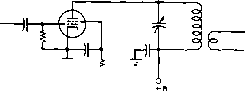 SERIES RESISTOR- О LOW VOLTAGE SCREEN SUPPLY Figure 35 A PROTECTIVE WATTAGE-LIMITING RESISTOR FOR USE WITH LOW-VOLTAGE SCREEN SUPPLY 1 ... 23 24 25 26 27 28 29 ... 80 |
|
© 2026 AutoElektrix.ru
Частичное копирование материалов разрешено при условии активной ссылки |