 |
 |
 |
| Главная Журналы Популярное Audi - почему их так назвали? Как появилась марка Bmw? Откуда появился Lexus? Достижения и устремления Mercedes-Benz Первые модели Chevrolet Электромобиль Nissan Leaf |
Главная » Журналы » Simple coaxial reflectometer 1 ... 24 25 26 27 28 29 30 ... 80 HANDBOOK Interstage Coupling 271 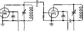 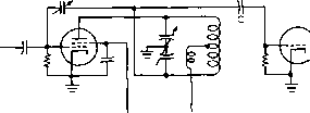 Figure 36 CAPACITIVE INTERSTAGE COUPLING a parasitic oscillation will take place in the stage being driven. One main disadvantage of capacitive coupling lies in the fact that the grid-to-filament capacitance of the driven tube is placed directly across the driver tuned circuit. This condition sometimes makes the r-f amplifier difficult to neutralize, and the increased minimum circuit capacitance makes it difficult to use a reasonable size coil in the v-h-f range. Difficulties from this source can be partially eliminated by using a center-tapped or split-stator tank circuit in the plate of the driver stage, and coupling capacitively to the opposite end from the plate. This method places the plate-to-filament capacitance of the driver across one-half of the tank and the grid-to-filament capacitance of the following stage across the other half. This type of coupling is shown in figure 37. Capacitive coupling can be used to advantage in reducing the total number of tuned circuits in a transmitter so as to conserve space and cost. It also can be used to advantage between stages for driving beam tetrode or pentode amplifier or doubler stages. Inductive Inductive coupling (figure 38) re-Coupling suits when two coils are electro-ma gnetically coupled to one another. The degree of coupling is controlled by varying the mutualinductance of the two coils, which is accomplished by changing the spacing or the relationship between the axes of the coils. 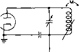
Figure 37 BALANCED CAPACITIVE COUPLING Balanced capacHive coupling sometimes is useful when it is desirable to use a relatively large inductance in the interstage tank circuit, or where the exciting stage is neutralized as shown above. Inductive coupling is used extensively for coupling r-f amplifiers in radio receivers. However, the mechanical problems involved in adjusting the degree of coupling limit the usefulness of direct inductive coupling in transmitters. Either the primary or the secondary or both coils may be tuned. Unity Coupling If the grid tuning capacitor of figure 38 is removed and the coupling increased to the maximum practicable value by interwindingthe turns of the two coils, the circuit insofar as r.f. is concerned acts like that of figure 36, in which one tank serves both as plate tank for the driver and grid tank for the driven stage. The inter-wound grid winding serves simply to isolate the d-c plate voltage of the driver from the grid of the driven stage, and to provide a return for d-c grid current. This type of coupling, illustrated in figure 39, is commonly known as unity coupling. Because of the high mutual inductance, both primary and secondary are resonated by the one tuning capacitor. INTERWOUND 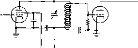 Figure 38 INDUCTIVE INTERSTAGE COUPLING Figure 39 UNITY INDUCTIVE COUPLING Due to the high value of coupling between the two coils, one tuning capacitor tunes both Circuits. This arrangement often is useful in coupling from a single-ended to a push-pull stage. 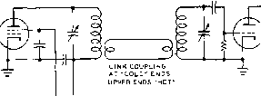 Figure 40 INTERSTAGE COUPLING BY MEANS OF A LINK Link interstage coupling is very commonly used since the two stages may be seporoted by a considerable distance, since the amount of a coupling between the two stages may be easily varied, and since the capacitances of the two stages may be isolated to permit use of larger inductances in the v-h-f range. Link Coupling A special form of inductive coupling which is widely employed in radio transmitter circuits is known as link coupling. A low impedance r-f transmission line couples the two tuned circuits together. Each end of the line is terminated in one or more turns of wire, or links, wound around the coils which are being coupled together. These links should be coupled to each tuned circuit at the point of zero r-f potential, or nodal point. A ground connection to one side of the link usually is used to reduce harmonic coupling, or where capacitive coupling between two circuits must be minimized. Coaxial line is commonly used to transfer energy between the two coupling links, although Twin-Lead may be used where harmonic attenuation is not so important. Typical link coupled circuits are shown in figures 40 and 41. Some of the advantages of link coupling are the following: (1) It eliminates coupling taps on tuned circuits. (2) It permits the use of series power supply connections in both tuned grid and tuned plate circuits, and thereby eliminates the need of shunt-feed r-f chokes. (3) It allows considerable separation between transmitter stages without appreciable r-f losses or stray chassis currents. (4) It reduces capacitive coupling and thereby makes neutralization more easily attainable in r-f amplifiers. (5) It provides semi-automatic impedance matching between plate and grid tuned circuits, with the result that greater grid drive can be obtained in comparison to capacitive coupling. (6) It effectively reduces the coupling of harmonic energy. 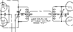 Figure 41 PUSH-PULL LINK COUPLING The link-coupling line and links can be made of no. 18 push-back wire for coupling between low-power stages. For coupling between higher powered stages the 150-ohm Twin-Lead transmission line is quite effective and has very low loss. Coaxial transmission is most satisfactory between high powered amplifier stages, and should always be used where harmonic attenuation is important. 13-14 Radio-Frequency Chokes Radio-frequency chokes are connected in circuits for the purpose of stopping the passage of r-f energy while still permitting a direct current or audio-frequency current to pass. They consist of inductances wound with a large number of turns, either in the form of a solenoid, a series of solenoids, a single universal pie winding, or a series of pie windings. These inductors are designed to have as much inductance and as little distributed or shunt capacitance as possible. The unavoidable small amount of distributed capacitance resonates the inductance, and this frequency normally should be much lower than the frequency at which the transmitter or receiver circuit is operating. R-f chokes for operation on several bands must be designed carefully so that the impedance of the choke will be extremely high (several hundred thousand ohms) in each of the bands. The direct current which flows througli the r-f choke largely determines the size of wire to be used in the winding. The inductance of r-f chokes for the v-h-f range is much less than for chokes designed for broadcast and ordinary short-wave operation. A very high inductance r-f choke has more distributed capacitance than a smaller one, with the result HANDBOOK Shunt and Series Feed 273 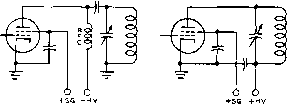 PARALLEL PLATE FEED SERIES PLATE FEED Figure 42 ILLUSTRATING PARALLEL AND SERIES PLATE FEED Parallel plate feed is desirable from a safety startdpoint since the tank circuit is at ground potential with respect ta d.c. However, a high-impedance r-f choke is required, and the r-f choke must be able to withstand the peak r-f voltage output of the tube. Series plate feed eliminates the requirement for a high-performance r-f choke, but requires the use of a relatively large value of by-pass capacitance at the bottom end of the tank circuit, as contrasted to the moderate value of coupling capacitance which may be used at the top of the tank circuit for parallel plate feed. that it will actually offer less impedance at very high frequencies. Another consideration, just as important as the amount of d.c. the winding will carry, is the r-f voltage which may be placed across the choke without its breaking down. This is a function of insulation, turn spacing, frequency, number and spacing of pies and other factors. Some chokes which are designed to have a high impedance over a very wide range of frequency are, in effect, really two chokes: a u-h-f choke in series with a high-frequency choke. A choke of this type is polarized; that is, it is important that the correct end of the combination choke be connected to the hot side of the circuit. Shtfnt ond Series Feed Direct-current grid and plate connections are made either by series or parallel feed systems. Simplified forms of each are shown in figures 42 and 43. Series feed can be defined as that in which the d-c connection is made to the grid or plate circuits at a point of very low r-f potential. Shunt feed always is made to a point of high r-f voltage and always requires a high impedance r-f choke or a relatively high resistance to prevent waste of r-f power. -BIAS PARALLEL BIAS FEED 7Г 0 - bias SERIES BIAS FEED Figure 43 ILLUSTRATING SERIES AND PARALLEL BIAS FEED 13-15 Parallel and Push-Pull Tube Circuits The comparative r-f power output from parallel or push-pull operated amplifiers is the same if proper impedance matching is accomplished, if sufficient grid excitation is available in both cases, and if the frequency of measurement is considerably lower than the frequency limit of the tubes. Poroilel Operating tubes in parallel has Operation some advantages in transmitters designed for operation below 10 Mc, particularly when tetrode or pentode tubes are to be used. Only one neutralizing capacitor is required for parallel operation of triode tubes, as against two for push-pull. Above about 10 Mc, depending upon the tube type, parallel tube operation is not ordinarily recommended with triode tubes. However, parallel operation of grounded-grid stages and stages using low-C beam tetrodes often will give excellent results well into the v-h-f range. Push-Pull The push-pull connection provides Operation a well-balanced circuit insofar as miscellaneous capacitances are concerned; in addition, the circuit can be neutralized more completely, especially in high-frequency amplifiers. The L/C ratio in a push-pull amplifier can be made higher than in a plate-neutralized parallel-tube operated amplifier. Push-pull amplifiers, when perfectly balanced, have less second-harmonic output than parallel or single-tube amplifiers, but in practice undesired capacitive coupling and circuit unbalance more or less offset the theoretical harmonic-reducing advantages of push-pull r-f circuits. CHAPTER FOURTEEN R-F Feedback Comparatively high gain is required in single sideband equipment because the signal is usually generated at levels of one watt or less. To get from this level to a kilowatt requires about 30 db of gain. High gain tetrodes may be used to obtain this increase with a minimum number of stages and circuits. Each stage contributes some distortion; therefore, it is good practice to keep the number of stages to a minimum. It is generally considered good practice to Operate the low level amplifiers below their maximum power capability in order to confine most of the distortion to the last two amplifier stages. R-f feedback can then be utilized to reduce the distortion in the last two stages. This type of feedback is no different from the common audio feedback used in high fidelity sound systems. A sample of the output waveform is applied to the amplifier input to correct the distortion developed in the amplifier. The same advantages can be obtained at radio frequencies that are obtained at audio frequencies when feedback is used. 14-1 R-F Feedback Circuits R-f feedback circuits have been developed by the Collins Radio Co. for use with linear amplifiers. Tests with large receiving and small transmitting tubes showed that amplifiers using these tubes without feedback developed signal-to-distortion ratios no better than 30 db or so. Tests were run employing cathode follower circuits, such as shown in figure lA. Lower distortion was achieved, but at the cost of low gain per stage. Since the voltage gain through the tube is less than unity, all gain has to be achieved by voltage step-up in the tank circuits. This gain is limited by the dissipation of the tank coils, since the circuit capacitance across the coils in a typical transmitter is quite high. In addition, the tuning of such a stage is sharp because of the high Q circuits. The cathode follower performance of the tube can be retained by moving the r-f ground R-F INC О о B-l- blAS = ® 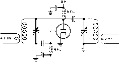 F OUT ® Figure 1 SIMILAR CATHODE FOLLOWER CIRCUITS HAVING DIFFERENT R-F GROUND POINTS. о Figure 2 SINGLE STAGE AMPLIFIER WITH R-F FEEDBACK CIRCUIT 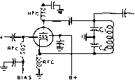 Figure 3 SINGLE STAGE FEEDBACK AMPLIFIER WITH GROUND RETURN POINT MODIFIED FOR UNBALANCED INPUT AND OUTPUT CONNECTIONS. point of the circuit from the plate to the cathode as shown in figure IB. Both ends of the input circuit are at high r-f potential so inductive coupling to this type of amplifier is necessary. Inspection of figure IB shows that by moving the top end of the input tank down on a voltage divider tap across the plate tank circuit, the feedback can be reduced from 100%, as in the case of the cathode follower circuit, down to any desired value. A typical feedback circuit is illustrated in figure 2. This circuit is more practical than those of figure 1, since the losses in the input tank are greatly reduced. A feedback level of 12 db may be achieved as a good compromise between distortion and stage gain. The voltage developed across C2 will be three times the grid-cathode voltage. 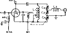 Figure 4 R-F AMPLIFIER WITH FEEDBACK AND IMPEDANCE MATCHING OUTPUT NETWORK. Tuning and loading are accomplished by Ci and C. Cl and Li are tuned in unison to establish the correct degree of feedbael(. Inductive coupling is required for this circuit, as shown in the illustration. The circuit of figure 3 eliminates the need for inductive coupling by moving the r-f ground to the point common to both tank circuits. The advantages of direct coupling between stages far outweigh the disadvantages of having the r-f feedback voltage appear on the cathode of the amplifier tube. In order to match the amplifier to a load, the circuit of figure 4 may be used. The ratio of XLi to XCi determines the degree of feedback, so it is necessary to tune them in unison when the frequency of operation is changed. Tuning and loading functions are accomplished by varying C2 and G. L: may also be varied to adjust the loading. Feedback Around a Two-Stage Amplifier The maximum phase shift obtainable over two simple tuned circuits does not exceed 180 degrees, and feedback around a two stage amplifier is possible-The basic circuit of a two stage feedback amplifier is shown in figure 5. This circuit is a conventional two-stage tetrode amplifier except that r-f is fed back from the plate circuit of the PA tube to the cathode of the driver tube. This will reduce the distortion О о о о Figure 5 BASIC CIRCUIT OF TWO-STAGE AMPLIFIER WITH R-F FEEDBACK Feedback voltage is obtained from a voltage divider across the output circuit and applied directly ta the cathode of the first tube. The input tank circuit is thus outside the feedback loop. of both tubes as effectively as using individual feedback loops around each stage, yet will allow a higher level of overall gain. With only two tuned circuits in the feedback loop, it is possible to use 12 to 15 db of feedback and still leave a wide margin for stability. It is possible to reduce the distortion by nearly as many db as are used in feedback. This circuit has two advantages that are lacking in the single stage feedback amplifier. First, the filament of the output stage can now be operated at r-f ground potential. Second, any conventional pi output network may be used. R-f feedback will correct several types of distortion. It will help correct distortion caused by poor power supply regulation, too low grid bias, and limiting on peaks when the plate voltage swing becomes too high. NeutrolizoHon and R-F Feedback The purpose of neutralization of an r-f amplifier stage is to balance out effects of the grid-plate capacitance coupling in the amplifier. In a conventional amplifier using a tetrode tube, the effective input capacity is given by: Input Capacitance = Cm + Cgp (1 + A cos where: Cin = tube input capacitance Ckp = grid-plate capacitance A = voltage amplification from grid to plate в - phase angle of load In a typical unneutralized tetrode amplifier having a stage gain of ЗЗз the input capacitance of the tube with the plate circuit in resonance is increased by 8 /iA fd. due to the unneutraiized grid-plate capacitance. This is unimportant in amplifiers where the gain (A) remains constant but if the tube gain varies, serious detuning and r-f phase shift may result. A grid or screen modulated r-f amplifier is an example of the case where the stage gain varies from a maximum down to zero. The gain of a tetrode r-f amplifier operating below plate current saturation varies with loading so that if it drives a following stage into grid current the loading increases and the gain falls off. The input of the grid circuit is also affected by the grid-plate capacitance, as shown in this equation: Input Resistance 2ni X G.., (AsinO) cult is inductive there is energy transferred from the plate to the grid circuit (positive feedback) which will introduce negative resistance in the grid circuit. When this shunt negative resistance across the grid circuit is lower than the equivalent positive resistance of the grid loading, circuit losses, and driving source impedance, the amplifier will oscillate. When the plate circuit is in resonance (phase angle equal to zero) the input resistance due to the grid-plate capacitance becomes infinite. As the plate circuit is tuned to the capacitive side of resonance, the input resistance becomes positive and power is actually transferred from the grid to the plate circuit. This is the reason that the grid current in an unneutraiized tetrode r-f amplifier varies from a low value with the plate circuit tuned on the low frequency side of resonance to a high value on the high frequency side of resonance The grid current is proportional to the r-f voltage on the grid which is varying under these conditions. In a tetrode class ABi amplifier, the effect of grid-plate feedback can be observed by placing a r-f voltmeter across the grid circuit and observing the voltage change as the plate circuit is tuned through resonance. If the amplifier is over-neutralized, the effects reverse so that with the plate circuit tuned to the low frequency side of resonance the grid voltage is high, and on the high frequency side of resonance, it is low. Amplifier Neutralization Check This resistance is in shunt with the grid current loading, grid tank circuit losses, and driving source impedance. When the plate cir- A useful rule of thumb method of checking neutralization of an amplifier stage (assuming that it is nearly correct to start with) is to tune both grid and plate circuits to resonance. Then, observing the r-f grid current, tune the plate circuit to the high frequency side of resonance. If the grid current rises, more neutralization capacitance is required. Conversely, if the grid current decreases, less capacitance is needed-This indication is very sensitive in a neutralized triode amplifier, and correct neutralization exists when the grid current peaks at the point of plate current dip. In tetrode power amplifiers this indication is less pronounced. Sometimes in a supposedly neutralized tetrode amplifier, there is practically no change in grid voltage as the plate circuit is tuned through resonance, and in some amplifiers it is unchanged on one side of resonance and drops slightly on the other side. Another observation sometimes made is a small dip in the center of a broad peak of grid current. These various effects are probably caused by HANDBOOK R-F Feedback Circuits 277 о ±-- = R-F 1 N Figure 6 SINGLE STAGE R-F AMPLIFIER WITH FEEDBACK RATIO OF C,/C, to C,;p/C,/ DETERMINES STAGE NEUTRALIZATION Cup;---, (1Л Figure 7 NEUTRALIZED AMPLIFIER AND INHERENT FEEDBACK CIRCUIT. Neutralizatian is achieved by varying the capacity af Cn, coupling from the plate to the grid circuit through other paths which are not balanced out by the particular neutralizing circuit used. Feedback and Neutralization of a One-Stage R-F Amplifier Figure 6 shows an r-f amplifier with negative feedback. The voltage developed across C4 due to the voltage divider action of Сз and G is introduced in series with the voltage developed across the grid tank circuit and is in phase-opposition to it. The feedback can be made any value from zero to 100% by properly choosing the values of G and G. For reasons stated previously, it is necessary to neutralize this amplifier, and the relationship for neutralization is: G Cgp It is often necessary to add capacitance from plate to grid to satisfy this relationship Figure 7 is identical to figure 6 except that it is redrawn to show the feedback inherent in this neutralization circuit more clearly. G and С replace Сз and G, and the main plate tank tuning capacitance is Cs. The circuit of figure 7 presents a problem in coupling to the grid circuit. Inductive coupling is ideal, but the extra tank circuits complicate the tuning of a transmitter which uses several cascaded amplifiers with feedback around each one. The grid could be coupled to a high source impedance such as a tetrode plate, but the driver then cannot use feedback because this would cause the source impedance to be low. A possible solution is to move the circuit ground point from the cathode to the bottom end of the grid tank circuit. The feedback voltage then appears between the cathode and ground (figure 8). The input can be capacitively coupled, and the plate of the amplifier can be capacitively coupled to the next stage. Also, cathode type transmitting tubes are available that allow the heater to remain at ground po- tential when r-f is impressed upon the cathode. The output voltage available with capacity coupling, of course, is less than the plate-cathode r-f voltage developed by the amount of feedback voltage across G. 14-2 Feedback and NeutralizaMon of a Two-Stage R-F Amplifier Feedback around two r-f stages has the advantage that more of tjhe tube gain can be realized and nearly as much distortion reduction can be obtained using 12 db around two stages as is realized using 12 db around each of two stages separately. Figure 9 shows a basic circuit of a two stage feedback amplifier. Inductive output coupling is used, although a pi-network configuration will also work well. The small feedback voltage required is obtained from the voltage divider G - G and is applied to the cathode of the driver tube. Cl is only a few /x/xfd., so this feedback voltage divider may be left fixed for a wide frequency range. If the combined tube gain is 160, and 12 db of feedback is desired, the ratio of C2 to Cl is about 40 to 1. This ratio in practice may be 400 yn/ufd. to 2.5 fifiid., for example. A complication is introduced into this simplified circuit by the cathode-grid capacitance 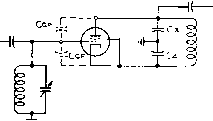 R-F OUT Figure 8 UNBALANCED INPUT AND OUTPUT CIRCUITS FOR SINGLE-STAGE R-F AMPLIFIER WITH FEEDBACK 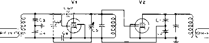 Figure 9 TWO-STAGE AMPLIFIER WITH FEEDBACK. Included IS a capacitor (Cs) tor neutralizing the cathode-grid capacity of the first tube. Vi is neutralized by capacitor Cs, and Vi is neutralized by the correct ratio of Ci/Сг. of the first tube which causes an undersired coupling to the input grid circuit. It is necessary to neutralize out this capacitance coupling, as illustrated in figure 9- The relationship for neutralization is: The input circuit may be made unbalanced by making C4 five times the capacity of G. This will tend to reduce the voltage across the coil and to minimize the power dissipated by the coil. For proper balance in this case, G must be five times the grid-filament capacitance of the tube. Except for tubes having extremely small grid-plate capacitance, it is still necessary to properly neutralize both tubes. If the ratio of G to G is chosen to be equal to the ratio of the grid-plate capacitance to the grid-filament capacitance in the second tube (Vz)* this tube will be neutralized. Tubes such as a 4X-150A have very low grid-plate capacitance and probably will not need to be neutralized when used in the first (Vi) stage. If neutralization is necessary, capacitor G is added for this purpose and the proper value is given by the following relationship: Gr G If neither tube requires neutralization, the bottom end of the interstage tank circuit may be returned to r-f ground. The screen and suppressor of the first tube should then be grounded to keep the tank output capacitance directly across this interstage circuit and to avoid common coupling between the feedback on the cathode and the interstage circuit. A slight amount of degeneration occurs in the first stage since the tube also acts as a grounded grid amplifier with the screen as the grounded grid. The ц of the screen is much lower than that of the control grid so that this effect may be unnoticed and would only require slightly more feedback from the output stage to overcome. Tests For Neutralizing the circuit of Neutralization figure 9 balances out coupling between the input tank circuit and the output tank circuit, but it does not remove all coupling from the plate circuit to the grid-cathode tube input. This latter coupling is degenerative, so applying a signal to the plate circuit will cause a signal to appear between grid and cathode, even though the stage is neutralized. A bench test for neutralization is to apply a signal to the plate of the tube and detect the presence of a signal in the grid coil by inductive coupling to it. No signal will be present when the stage is neutralized. Of course, a signal could be inductively coupled to the input and neutralization accomplished by adjusting one branch of the neutralizing circuit bridge (G for example) for minimum signal on the plate circuit. Neutralizing the cathode-grid capacitance of the first stage of figure 9 may be accomplished by applying a signal to the cathode of the tube and adjusting the bridge balance for minimum signal on a detector inductively coupled to the input coil. Tuning a Two-Stage Feedback Amplifier Tuning the two-stage feedback amplifier of figure 9 is accomplished in an unconventional way because the output circuit cannot be tuned for maximum output signal. This is because the output circuit must be tuned so the feedback voltage applied to the cathode is in-phase with the input signal applied to the first grid. When the feedback voltage is not in-phase, the resultant grid-cathode voltage increases as shown in figure 10. When the output circuit is properly tuned, the resultant grid-cathode voltage on the first tube will be at a minimum, and the voltage on the interstage tuned circuit will also be at a minimum. HANDBOOK Neutralization 279 VOLTACE-INPUr URID < TO CROUND VOLTACE- CRID TO CATHODE >VOLTAGE-CATHODE TO GROUND  Figure 10 VECTOR RELATIONSHIP OF FEEDBACK VOLTAGE A = Output Circuit Properly Tuned B -Output Circuit Mis-Tuned The two-stage amplifier may be tuned by placing a r-f voltmeter across the interstage tank circuit ( hot side to ground) and tuning the input and interstage circuits for maximum meter reading, and tuning the output circuit for minimum meter reading. If the second tube is driven into the grid current region, the grid current meter may be used in place of the r-f voltmeter. On high powered stages where operation is well into the Class AB region, the plate current dip of the output tube indicates correct output circuit tuning, as in the usual amplifier. Parositic Oscillations in the Feedback Amplifier Quite often low fre-q u e n с у parasitics may be found in the interstage circuit of the two-stage feedback amplifier. Oscillation occurs in the first stage due to low frequency feedback in the cathode circuit. R-f chokes, coupling capacitors, and bypass capacitors provide the low frequency tank circuits. When the feedback and second stage neutralizing circuits are combined, it is necessary to use the configuration of figure 11. This circuit has the advantage that only one capacitor (G) is required from the plate of the output tube, thus keeping the added capacitance across the output tank at a minimum. Ci Сг gRFC BIAS Figure 11 INTERSTAGE CIRCUIT COMBINING NEUTRALIZATION AND FEEDBACK NETWORKS. 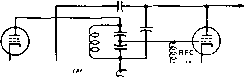 1 /si Figure 12 INTERSTAGE CIRCUIT WITH SEPARATE NEUTRALIZING AND FEEDBACK CIRCUITS. It is convenient, however, to separate these circuits so neutralization and feedback can be adjusted independently. Also, it may be desirable to be able to switch the feedback out of the circuit. For these reasons, the circuit shown in figure 12 is often used. Switch Si removes the feedback loop when it is closed. A slight tendency for low frequency parasitic oscillations still exists with this circuit. Ll should have as little inductance as possible without upsetting the feedback. If the value of Ll is too low, it cancels out part of the reactance of feedback capacitor C4 and causes the feedback to increase at low values of radio frequency. In some cases, a swamping resistor may be necessary across Li. The value of this resistor should be high compared to the reactance of G to avoid phase-shift of the r-f feedback. 14-3 Neutralization Procedure in Feedback-Type Amplifiers Experience with feedback amplifiers has brought out several different methods of neutralizing. An important observation is that when all three neutralizing adjustments are correctly made the peaks and dips of various tuning meters all coincide at the point of circuit resonance. For example, the coincident indications when the various tank circuits are tuned through resonance with feedback operating are: A-When the PA plate circuit is tuned through resonance: 1-PA plate current dip 2-Power output peak 3-PA r-f grid voltage dip 4-PA grid current dip (Note: The PA grid current peaks when feedback circuit is disabled and the tube is heavily driven) 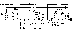 ; ccp BIAS Figure 13 TWO-STAGE AMPLIFIER WITH FEED BACK CIRCUIT. В-When the PA grid circuit is tuned through resonance: 1-Driver plate current dip 2-PA r-f grid voltage peak 3-PA grid current peak 4-PA power output peak С-When the driver grid circuit is tuned through resonance: 1-Driver r-f grid voltage peak 2-Driver plate current peak 3-PA r-f grid current peak 4-PA plate current peak 5-PA power output peak Four meters may be employed to measure the most important of these parameters. The meters should be arranged so that the following pairs of readings are displayed on meters located close together for ease of observation of coincident peaks and dips: 1-PA piate current and power output 2-PA r-f grid current and PA plate current 3-PA r-f grid voltage and power output 4-Driver plate current and PA r-f grid voltage The third pair listed above may not be necessary if the PA plate current dip is pronounced. When this instrumentation is provided, the neutralizing procedure is as follows: 1-Remove the r-f feedback OPEN 2- Neutralize the grid-plate capacitance of the driver stage 3-Neutralize the grid-plate capaci- Figure 14 FEEDBACK SHORTING DEVICE. tance of the power amplifier (PA) stage 4-Apply r-f feedback 5-Neutralize driver grid-cathode capacitance These steps will be explained in more detail in the following paragraphs: Step 1. The removal of r-f feedback through the feedback circuit must be complete. The switch (Si) shown in the feedback circuit (figure 13) is one satisfactory method. Since G is effectively across the PA plate tank circuit it is desirable to keep it across the circuit when feedback is removed to avoid appreciable detuning of the plate tank circuit. Another method that can be used if properly done is to ground the junction of G and G. Grounding this common point through a switch or relay is not good enough because of common coupling through the length of the grounding lead. The grounding method shown in figure 14 is satisfactory. Step 2. Plate power and excitation are applied. The driver grid tank is resonated by tuning for a peak in driver r-f grid voltage or driver plate current. The power amplifier grid tank circuit is then resonated and adjusted for a dip in driver plate current. Driver neutralization is now adjusted until the PA r-f grid voltage (or PA grid current) peaks at exactly the point of driver plate current dip. A handy rule for adjusting grid-plate neutralization of a tube without feedback: with all circuits in resonance, detune the plate circuit to the high frequency side of resonance: If grid current to next stage (or power output of the stage under test) increases, more neutralizing capacitance is required and vice versa. If the driver tube operates class A so that a plate current dip cannot be observed, a dif- 1 ... 24 25 26 27 28 29 30 ... 80 |
||||||
|
© 2026 AutoElektrix.ru
Частичное копирование материалов разрешено при условии активной ссылки |