 |
 |
 |
| Главная Журналы Популярное Audi - почему их так назвали? Как появилась марка Bmw? Откуда появился Lexus? Достижения и устремления Mercedes-Benz Первые модели Chevrolet Электромобиль Nissan Leaf |
Главная » Журналы » Simple coaxial reflectometer 1 ... 25 26 27 28 29 30 31 ... 80 о о о Ц=С9 Сю Figure 15 FEEDBACK NEUTRALIZING CIRCUIT USING AUXILIARY RECEIVER. ferent neutralizing procedure is necessary This will be discussed in a subsequent section. Step 3- This is the same as step 2 except it is applied to the power amplifier stage. Adjust the neutralization of this stage for a peak in power output at the plate current dip. Step 4. Reverse step 1 and apply the r-f feedback. Step 5. Apply plate power and an exciting signal to drive the amplifier to nearly full output. Adjust the feedback neutralization for a peak in amplifier power output at the exact point of minimum amplifier plate current. Decrease the feedback neutralization capacitance if the power output rises when the tank circuit is tuned to the high frequency side of resonance. The above sequence applies when the neutralizing adjustments are approximately correct to start with. If they are far off, some cut-and-try adjustment may be necessary. Also, the driver stage may break into oscillation if the feedback neutralizing capacitance is not near the correct setting. It is assumed that a single tone test signal is used for amplifier excitation during the above steps, and that all tank circuits are at resonance except the one being detuned to make the observation. There is some interaction between the driver neutralization and the feedback neutralization so if an appreciable change is made in any adjustment the others should be rechecked. It is important that the grid-plate neutralization be accomplished first when using the above procedure, otherwise the feedback neutralization will be off a little, since it partially compensates for that error. Neutralization The method of neutralization Techniques employing a sensitive r-f de- tector inductively coupled to a tank coil is difficult to apply in some cases because of mechanical construction of the equipment, or because of undesired coupling. Another method for observing neutralization can be used, which appears to be more accurate in actual practice. A sensitive r-f detector such as a receiver is loosely coupled to the grid of the stage being neutralized, as shown in figure 15- The coupling capacitance is of the order of one or two /ijiid. It must be small enough to avoid upsetting the neutralization when it is removed because the total grid-ground capacitance is one leg of the neutralizing bridge. A signal generator is connected at point S and the receiver at point R. If Go is not properly adjusted the S-meter on the receiver will either kick up or down as the grid tank circuit is tuned through resonance. Go may be adjusted for minimum deflection of the S-meter as the grid circuit is tuned through resonance. The grid-plate capacitance of the tube is then neutralized by connecting the signal generator to the plate of the tube and adjusting Gi of figure 13 for minimum deflection again as the grid tank is tuned through resonance. The power amplifier stage is neutralized in the same manner by connecting a receiver loosely to the grid circuit, and attaching a signal generator to the plate of the tube. The r-f signal can be fed into the amplifier output terminal if desired. Some precautions are necessary when using this neutralization method. First, some driver tubes (the 6CL6, for example) have appreciably more effective input capacitance when in operation and conducting plate current than when in standby condition. This increase in input capacitance may be as great as three or four fj.fj.id, and since this is part of the neutralizing bridge circuit it must be taken into consideration. The result of this change in input capacitance is that the neutralizing adjustment of such tubes must be made when they are conducting normal plate current. Stray coupling must be avoided, and it may prove helpful to remove filament power from the preceding stage or disable its input circuit in some manner. It should be noted that in each of the above adjustments that minimum reaction on the grid is desired, not minimum voltage. Some residual voltage is inherent on the grid when this neutralizing circuit is used. CHAPTER FIFTEEN e Modulation If the output of a c-w transmitter is varied in amplitude at an audio frequency rate instead of interrupted in accordance with code characters, a tone will be heard on a receiver tuned to the signal. If the audio signal consists of a band of audio frequencies comprising voice or music intelligence, then the voice or music which is superimposed on the radio frequency carrier will be heard on the receiver. When voice, music, video, or other intelligence is superimposed on a radio frequency carrier by means of a corresponding variation in the amplitude of the radio frequency output of a transmitter, amplitude modulation is the result. Telegraph keying of a c-w transmitter is the simplest form of amplitude modulation, while video modulation in a television transmitter represents a highly complex form. Systems for modulating the amplitude of a carrier envelope in accordance with voice, music, or similar types of complicated audio waveforms are many and varied, and will be discussed later on in this chapter. 15-1 Sidebands Modulation is essentially a form of mixing or combining already covered in a previous chapter. To transmit voice at radio frequencies by means of amplitude modulation, the voice frequencies are mixed with a radio frequency carrier so that the voice frequencies are converted to radio frequency sidebands. Though it may be difficult to visualize, the amplitude of the radio frequency carrier does not vary during conventional amplitude modulation. Even though the amplitude of radio frequency voltage representing the composite signal (resultant of the carrier and sidebands, called the envelope) will vary from zero to twice the unmodulated signal value during full modulation, the amplitude of the carrier component does not vary. Also, so long as the amplitude of the modulating voltage does not vary, the amplitude of the sidebands will remain constant. For this to be apparent, however, it is necessary to measure the amplitude of each component with a highly selective filter. Otherwise, the measured power or voltage will be a resultant of two or more of the components, and the amplitude of the resultant will vary at the modulation rate. If a carrier frequency of 5000 kc. is modulated by a pure tone of 1000 cycles, or 1 kc, two sidebands are formed: one at 5001 kc. (the sum frequency) and one at 4999 kc. (the difference frequency). The frequency of each sideband is independent of the amplitude of the modulating tone, or modulation percentage; the frequency of each sideband is determined only by the frequency of the modulating tone. This assumes, of course, that the transmitter is not modulated in excess of its linear capability. 5652 Modulation When the modulating signal consists of multiple frequencies, as is the case with voice or music modulation, two sidebands will be formed by each modulating frequency (one on each side of the carrier), and the radiated signal will consist of a band of frequencies. The band width, or channel taken up in the frequency spectrum by a conventional double-sideband amplitude-modulated signal, is equal to twice the highest modulating frequency. For example, if the highest modulating frequency is 5000 cycles, then the signal (assuming modulation of complex and varying waveform) will occupy a band extending from 5000 cycles below the carrier to 5000 cycles above the carrier. Frequencies up to at least 2500 cycles, and preferably 3500 cycles, are necessary for good speech intelligibility. If a filter is incorporated in the audio system to cut out all frequencies above approximately 300Q cycles, the band width of a radio-telephone signal can be limited to 6 kc. without a significant loss in intelligibility. However, if harmonic distortion is introduced subsequent to the filter, as would happen in the case of an overloaded modulator or overmodulation of the carrier, new frequencies will be generated and the signal will occupy a band wider than 6 kc. 15-2 Mechanics of Modulation A c-w or unmodulated r-f carrier wave is represented in figure lA. An audio frequency sine wave is represented by the curve of figure IB. When the two are combined or mixed, the carrier is said to be amplitude modulated, and a resultant similar to 1С or ID is obtained. It should be noted that under modulation, each half cycle of r-f voltage differs slightly from the preceding one and the following one; therefore at no time during modulation is the r-f waveform a pure sine wave. This is simply another way of saying that during modulation, the transmitted r-f energy no longer is confined to a single radio frequency. It will be noted that the average amplitude of the peak r-f voltage, or modulation envelope, is the same with or without modulation. This simply means that the modulation is symmetrical (assuming a symmetrical modulating wave) and that for distortionless modulation the upward modulation is limited to a value of twice the unmodulated carrier wave amplitude because the amplitude cannot go below zero on downward portions of the modulation cycle. Figure ID illustrates the maxi- C.W. OR UNMODULATED CARRIER 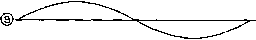 SINE WAVE AUDIO SIGNAL FROM MODULATOR 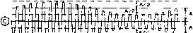 llli-llOJiL -! 50% MODULATED CARRIER Ц ft/Vv-W\fl 100% MODULATED CARRIER Figure 1 AMPLITUDE MODULATED WAVE Гер drawing (A) represents an unmodulated carrier wave; (B) shows the audio output of the modulator. Drawing (C) shows the audio signal impressed on the carrier wave to the extent of 50 per cent modulation; (D) shows the carrier with 100 per cent amplitude modulation. mum obtainable distortionless modulation with a sine modulating wave, the r-f voltage at the peak of the r-f cycle varying from zero to twice the unmodulated value, and the r-f power varying from zero to four times the unmodulated value (the power varies as the square of the voltage). While the average r-f voltage of the modulated wave over a modulation cycle is the same as for the unmodulated carrier, the average power increases with modulation. If the radio frequency power is integrated over the audio cycle, it will be found with 100 per cent sine wave modulation the average r-f power has increased 50 per cent. This additional power is represented by the sidebands, because as previously mentioned, the carrier power does not vary under modulation. Thus, when a 100-watt carrier is modulated 100 per cent by a sine wave, the total r-f power is 150 watts; 100 watts in the carrier and 25 watts in each of the two sidebands. 91496852520682 Modulation So long as the relative propor- Percentage tion of the various sidebands making up voice modulation is maintained, the signal may be received and detected without distortion. However, the higher the average amplitude of the sidebands, the greater the audio signal produced at the receiver. For this reason it is desirable to increase the modulation percentage, or degree of modulation, to the point where maximum peaks just hit 100 per cent. If the modulation percentage is increased so that the peaks exceed this value, distortion is introduced, and if carried very far, bad interference to signals on nearby channels will result. ; ECAR ® ® Figure 2 GRAPHICAL DETERMINATIOII OF MODULATION PERCENTAGE ГЬе procedure for determining modulation percentage from the peak voltage points indicated Is discussed in the text. Modulation The amount by which a carrier Measurernent is being modulated may be expressed either as a modulation factor, varying from zero to 1.0 at maximum modulation, or as a percentage. The percentage of modulation is equal to 100 times the modulation factor. Figure 2A shows a carrier wave modulated by a sine-wave audio tone. A picture such as this might be seen on the screen of a cathode-ray oscilloscope with sawtooth sweep on the horizontal plates and the modulated carrier impressed on the vertical plates. The same carrier without modulation would appear on the oscilloscope screen as figure 2B. The percentage of modulation of the positive peaks and the percentage of modulation of the negative peaks can be determined separately from two oscilloscope pictures such as shown. The modulation factor of the positive peaks may be determined by the formula: F F max ca The factor for negative peaks may be determined from this formula: Fear - mia In the above two formulas E is the maximum carrier amplitude with modulation and Emm is the minimum amplitude; Ecar is the steady-state amplitude of the carrier without modulation. Since the deflection of the spot on a cathode-ray tube is linear with respect to voltage, the relative voltages of these various amplitudes may be determined by measuring the deflections, as viewed on the screen, with a rule calibrated in inches or centimeters. The percentage of modulation of the carrier may be had by multiplying the modulation factor thus obtained by 100. The above procedure assumes that there is no carrier shift, or change in average amplitude, with modulation. If the modulating voltage is symmetrical, such as a sine wave, and modulation is accomplished without the introduction of distortion, then the percentage modulation will be the same for both negative and positive peaks. However, the distribution and phase relationships of harmonics in voice and music waveforms are such that the percentage modulation of the negative modulation peaks may exceed the percentage modulation of the positive peaks, and vice versa. The percentage modulation when referred to without regard to polarity is an indication of the average of the negative and positive peaks. Modulation The modulation capability of a Copability transmitter is the maximum percentage to which that transmitter may be modulated before spurious sidebands are generated in the оифиг or before the distortion of the modulating waveform becomes objectionable. The highest modulation capability which any transmitter may have on the negative peaks is 100 per cent. The maximum permissible modulation of many transmitters is less than 100 per cent, especially on positive peaks. The modulation capability of a transmitter may be limited by tubes with insufficient filament emission, by insufficient excitation or grid bias to a plate-modulated stage, too light loading of any type of amplifier carrying modulated r.f., insufficient power output capability in the modulator, or too much excitation to a grid-modulated stage or a Class В linear amplifier. In any case, the FCC regulations specify that no transmitter be modulated in excess of its modulation capability. Hence, it is desirable to make the modulation capability of a transmitter as near as possible to 100 per cent so that the carrier power may be used most effectively. HANDBOOK Modulation Systems 285 Speech Waveform The manner in which the Dissymmetry human voice is produced by the vocal cords gives rise to a certain dissymmetry in the waveform of voice sounds when they are picked up by a good-quality microphone. This is especially pronounced in the male voice, and more so on certain voiced sounds than on others. The result of this dissymmetry in the waveform is that the voltage peaks on one side of the average value of the wave will be considerably greater, often two or three times as great, as the voltage excursions on the other side of the zero axis. The average value of voltage on both sides of the wave is, of course, the same. As a result of this dissymmetiy in the male voice waveform, there is an optimum polaiity of the modulating voltage that must be observed if maximum sideband energy is to be obtained without negative peak clipping and generation of splatter on adjacent channels. A double-pole double-throw phase reversing switch in the input or output leads of any transformer in the speech amplifier system will permit poling the extended peaks in the direction of maximum modulation capability. The optimum polarity may be determined easily by listening on a selective receiver tuned to a frequency 30 to 50 kc. removed from the desired signal and adjusting the phase reversing switch to the position which gives the least splatter when the transmittei is modulated rather heavily. If desired, the switch then may be leplaced with permanent wiring, so long as the microphone and speech system are not to be changed. A more conclusive illustration of the lop-sidedness of a speech waveform may be obtained by observing the modulated waveform of a radiotelephone transmitter on an oscilloscope. A portion of the carrier energy of the transmitter should be coupled by means of a link directly to the vertical plates of the scope, and the horizontal sweep should be a sawtooth or similar wave occurring at a rate of approximately 30 to 70 sweeps per second. With the speech signal from the speech amplifier connected to the transmitter in one polarity it will be noticed that negative-peak clipping-as indicated by bright spots in the center of the scope pattern whenever the carrier amplitude goes to zero-will occur at a considerably lower level of average modulation than with the speech signal being fed to the transmitter in the other polarity. When the input signal to the transmitter is polarized in such a manner rhat the fingers of the speech wave extend in the direction of positive modulation these fingers usually will be clipped in the plate circuit of the modulator at an acceptable peak modulation level. The use of the proper polarity of the incoming speech wave in modulating a transmitter can afford an increase of approximately two to one in the amount of speech audio power which may be placed upon the carrier for an amplitude-modulated transmitter for the same amount of sideband splatter. More effective methods for increasing the amount of audio power on the carrier of an AM phone transmitter are discussed later in this chapter. Single-Sideband Because the same intelli-Transmission gibility is contained in each of the sidebands associated with a modulated carrier, it is not necessary to transmit sidebands on both sides of the carrier. Also, because the carrier is simply a single radio frequency wave of unvarying amplitude, it is not necessary to transmit the carrier if some means is provided for inserting a locally generated carrier at the receiver. When the carrier is suppressed but both upper and lower sidebands are transmitted, it is necessary to insert a locally generated carrier at the receiver of exactly the same frequency and phase as the carrier which was suppressed. For this reason, suppressed-carrier double-sideband systems have little practical application. When the carrier is suppressed and only the upper or the lower sideband is transmitted, a highly intelligible signal may be obtained at the receiver even though the locally generated carrier differs a few cycles from the frequency of the carrier which was suppressed at the transmitter. A communications system utilizing but one group of sidebands with carrier suppressed is known as a single sideband system. Such systems are widely used for commercial point to point work, and are being used to an increasing extent in amateur communication. The two chief advantages of the system are: ( 1) an effective power gain of about 9 db results from putting all the radiated power in intelligence carrying sideband frequencies instead of mostly into radiated carrier, and (2) elimination of the selective fading and distortion that normally occurs in a conventional double-sideband system when the carrier fades and the sidebands do not, or the sidebands fade differently. 15-3 Systems of Amplitude Modulation There are many different systems and methods for amplitude modulating a carrier, but most may be grouped under three general classifications: (1) variable efficiency systems in which the average input to the stage le- mains constant with and wittiout modulation and the variations in the efficiency of the stage in accordance with the modulating signal accomplish the modulation; (2) constant efficiency systems in which the input to the stage is varied by an external source of modulating energy to accomplish the modulation; and (3) so-called high-efficiency systems in which circuit complexity is increased to ob-high plate circuit efficiency in the modulated stage without the requirement of an external high-level modulator. The various systems under each classification have individual characteristics which make certain ones best suited to particular application*. Variable Efficiency Since the average input Modulation remains constant in a stage employing variable efficiency modulation, and since the average power output of the stage increases with modulation, the additional average power output from the stage with modulation must come from the plate dissipation of the tubes in the stage. Hence, for the best relation between tube cost and power output the tubes employed should have as high a plate dissipation rating per dollar as possible. The plate efficiency in such an amplifier is doubled when going from the unmodulated condition to the peak of the modulation cycle. Hence, the unmodulated efficiency of such an amplifier must always be less than 45 per cent, since the maximum peak efficiency obtainable in a conventional amplifier is in the vicinity of 90 per cent. Since the peak efficiency in certain types of amplifiers will be as low as 60 per cent, the unmodulated efficiency in such amplifiers will be in the vicinity of 30 per cent. Assuming a typical amplifier having a peak efficiency of 70 per cent, the following figures give an idea of the operation of an idealized efficiency-modulated stage adjusted for 100 per cent sine-wave modulation. It should be kept in mind that the plate voltage is constant at all times, even over the audio cycles. Plate input without modulation........100 watts Output without modulation.............. 35 watts Efficiency without modulation......... 35% Input on 100% positive modulation peak (plate current doubles)........200 watts Efficiency on 100% positive peak.... 70% Output on 100% positive modulation peak.................................140 watts Input on 100% negative peak.......... 0 watts Efficiency on 100% negative peak.... 0% Ouфut on 100% negative peak........ 0 watts Average input with 1007( modulation..............................100 watts Average оифиг with 100% modulation (35 watts carrier plus 17.5 watts sideband) ......................52.5 watts Average efficiency with 100% modulation..............................52.5% Systems of Efficiency There are many sys-Modulation tems of efficiency mod- ulation, but they all have the general limitation discussed in the previous paragraph-so long as the carrier amplitude is to remain constant with and without modulation, the efficiency at carrier level must be not greater than one-half the peak modulation efficiency if the stage is to be enable of 100 per cent modulation. The classic example of efficiency modulation is the Class В linear r-f amplifier, to be discussed below. The other three common forms of efficiency modulation are control-grid modulation, screen-grid modulation, and suppressor-grid modulation. In each case, including that of the Class В linear amplifier, note that the modulation, or the modulated signal, is impressed on a control electrode of the stage. The Class В This is the simplest practi- Linear Amplifier cable type amplifier for an amplitude-modulated wave or a single-sideband signal. The system possesses the disadvantage that excitation, grid bias, and loading must be carefully controlled to preserve the linearity of the stage. Also, the grid circuit of the tube, in the usual application where grid current is drawn on peaks, presents a widely varying value of load impedance to the source of excitation. Hence it is necessary to include some sort of swamping resistor to reduce the effect of grid-impedance variations with modulation. If such a swamping resistance across the grid tank is not included, or is too high in value, the positive modulation peaks of the incoming modulated signal will tend to be flattened with resultant distortion of the wave being amplified. The Class В linear amplifier has long been used in broadcast transmitters, but recently has received much more general usage in the h-f range for two significant reasons: (a) the Class В linear is an excellent way of increasing the power output of a single-sideband transmitter, since the plate efficiency with full signal will be in the vicinity of 70 per cent, while with no modulation the input to the stage drops to a relatively low value; and (b) the Class В linear amplifier operates with relatively low harmonic output since the grid bias on the stage normally is slightly less HANDBOOK Class В Linear Amplifier 287 tfian tfie value which will cut off plate current to the stage in the absence of excitation. Since a Qass В linear amplifier is biased to extended cutoff with no excitation (the grid bias at extended cutoff will be approximately equal to the plate voltage divided by the amplification factor for a triode, and will be approximately equal to the screen voltage divided by the grid-screen mu factor for a tetrode or pentode) the plate current will flow essentially in 180-degree pulses. Due to the relatively large operating angle of plate current flow the theoretical peak plate efficiency is limited to 78.5 per cent, with 65 to 70 per cent representing a range of efficiency normally attainable, and the harmonic output will be low. The carrier power output from a Class В linear amplifier of a normal 100 per cent modulated AM signal will be about one-half the rated plate dissipation of the stage, with optimum operating conditions. The peak ouфut from a Class В linear, which represents the maximum-signal output as a single-sideband amplifier, or peak output with a 100 per cent AM signal, will be about twice the plate dissipation of the tubes in the stage. Thus the carrier-level input power to a Class В linear should be about 1.5 times the rated plate dissipation of the stage. The schematic circuit of a Class В linear amplifier is the same as a conventional single-ended or push-pull stage, whether triodes or beam tetrodes are used. However, a swamping resistor, as mentioned before, must be placed across the grid tank of the stage if the operating conditions of the tube are such that appreciable gridcurrent will be drawn on modulation peaks. Also, a fixed source of grid bias must be provided for the stage- A regulated grid-bias power supply is the usual source of negative bias voltage. Adiustment of о Class With grid bias adjusted В Lineor Amplifier to the correct value, and with provision for varying the excitation voltage to the stage and the loading of the plte circuit, a fully modulated signal is applied to the grid circuit of the stage. Then with an oscilloscope coupled to the output of the stage, excitation and loading are varied until the stage is drawing the normal plate input and the output waveshape is a good replica of the input signal. The adjustment procedure normally will require a succession of approximations, until the optimum set of adjustments is attained. Then the modulation being applied to the input signal should be removed to check the linearity. With modulation removed, in the case of a 100 per cent AM signal, the input to the stage should remain constant, and the peak output of the r-f envelope should fall to half the value obtained on positive modulation peaks. Closs С . One widely used system of Grid Modulation efficiency modulation for communications work is Class С control-grid bias modulation. The distortion is slightly higher than for a properly operated Class В linear amplifier, but the efficiency is also higher, and the distortion can be kept within tolerable limits for communications Work. Class С grid modulation requires high plate voltage on the modulated stage, if maximum output is desired. The plate voltage is normally run about 50 per cent higher than for maximum output with plate modulation. The driving power required for operation of a grid-modulated amplifier under these conditions is somewhat more than is required for operation at lower bias and plate voltage, but the increased power output obtainable overbalances the additional excitation requirement. Actually, almost half as much excitation is required as would be needed if the same stage were to be operated as a Class С plate-modulated amplifier. The resistor R across the grid rank of the stage serves as swamping to stabilize the r-f driving voltage. At least 50 per cent of the output of the driving stage should be dissipated in this swamping resistor under carrier conditions. A comparatively small amount of audio power will be required to modulate the amplifier stage 100 per cent. An audio amplifier having 20 watts output will be sufficient to modulate an amplifier with one kilowatt input. Proportionately smaller amounts of audio will be required for lower powered stages. However, the audio amplifier that is being used as the grid modulator should, in any case, either employ low plate resistance tubes such as 2A3s, employ degenerative feedback from the oatput stage to one of the preceding stages of the speech amplifier, or be resistance loaded with a resistor across the secondary of the modulation transformer. This provision of low driv ing impedance in the grid modulator is to insure good regulation in the audio driver for the grid modulated stage. Good regulation of both the audio and the r-f drivers of a grid-modulated stage is quite important if distortion-free modulation approaching 100 per cent is desired, because the grid impedance of the modulated stage varies widely over the audio cycle. A practical circuit for obtaining grid-bias modulation is shown in figure 3- The modulator and bias regulator tube have been combined in a single 6B4G tube. The regulator-modulator tube operates as a cathode-follower. The average d-c voltage R.F. AMPLIflER 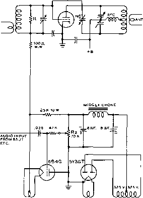 SMALL eo-eo MA. B.C. TBANSFORMEB Figure 3 GRID-BIAS MODULATOR CIRCUIT on the control grid is controlled by the 70, 000-ohm wire-wound potentiometer and this potentiometer adjusts the average grid bias on the modulated stage. However, a-c signal voltage is also impressed on the control-grid of the tube and since the cathode follows this a-c wave the incoming speech wave is superimposed on the average grid bias, thus effecting grid-bias modulation of the r-f amplifier stage. An audio voltage swing is required on the grid of the 6B4G of approximately the same peak value as will be required as bias-voltage swing on the grid-bias modulated stage. This voltage swing will normally be in the region from 50 to 200 peak volts. Up to about 100 volts peak swing can be obtained from a 6SJ7 tube as a conventional speech amplifier stage. The higher voltages may be obtained from a tube such as a 6J5 through an audio transformer of 2:1 or 2У2:1 ratio. With the normal amount of comparatively tight antenna coupling to the modulated stage, a non-modulated carrier efficiency of 40 per cent can be obtained with substantially distortion-free modulation up to practically 100 per cent. If the antenna coupling is decreased slightly from the condition just described, and the excitation is increased to the point where the amplifier draws the same input, carrier efficiency of 50 per cent is obtainable with tolerable distortion at 90 per cent modulation. Tuning the The most satisfactory pro- Grid-Bins cedure for tuning a stage Modulated Stage for grid-bias modulation of the Class С type is as follows. The amplifier should first be neutralized, and any possible tendency toward para-sitics under any condition of operation should be eliminated. Then the antenna should be coupled to the plate circuit, the grid bias should be run up to the maximum available value, and the plate voltage and excitation should be applied. The grid bias voltage should then be reduced until the amplifier draws the approximate amount of plate current it is desired to run, and modulation corresponding to about 80 per cent is then applied. If the plate current kicks up when modulation is applied, the grid bias should be reduced; if the plate meter kicks down, increase the grid bias. When the amount of bias voltage has been found (by adjusting the fine control, R2, on the bias supply) where the plate meter remains constant with modulation, it is more than probable that the stage will be drawing either too much or too little input. The antenna coupling should then be either increased or decreased (depending on whether the input was too little or too much, respectively) until the input is more nearly the correct value. The bias should then be readjusted until the plate meter remains constant with modulation as before. By slight jockeying back and forth of antenna coupling and grid bias, a point can be reached where the tubes are running at rated plate dissipation, and where the plate milliammeter on the modulated stage remains substantially constant with modulation. The linearity of the stage should then be checked by any of the conventional methods; the trezoidal pattern method employing a cathode-ray oscilloscope is probably the most satisfactory. The check with the trapezoidal pattern will allow the determination of the proper amount of gain to employ on the speech amplifier. Too much audio power on the grid of the modulated stage should not be used in the tuning-up process, as the plate meter will kick erratically and it will be impossible to make a satisfactory adjustment. Screen-Grid Amplitude modulation may be Modulation accomplished by varying the screen-grid voltage in a Class С amplifier which employs a pentode, beam tetrode, or other type of screen-grid tube. The modulation obtained in this way is not especially linear, but screen-grid modulation does offer other advantages and the linearity is quite adequate for communications work. There are two significant and worthwhile advantages of screen-grid modulation for communications work: (1) The excitation requirements for an amplifier which is to be modulated in the screen are not at all critical, and good regulation of the excitation voltage is not required. The normal rated grid-circuit operating conditions specified for Class С c-w operation are quite adequate for screen-grid modulation. (2) The audio modulating power requirements for screen-grid modulation are relatively low. A screen-grid modulated r-f amplifier operates as an efficiency-modulated amplifier, the same as does a Class В linear amplifier and a grid-modulated stage. Hence, plate circuit loading is relatively critical as in any efficiency-modulated stage, and must be adjusted to the correct value if normal power output with full modulation capability is to be obtained. As in the case of any efficiency-modulated stage, the operating efficiency at the peak of the modulation cycle will be between 70 and 80 per cent, with efficiency at the carrier level (if the stage is operating in the normal manner with full carrier) about half of the peak-modulation value. There are two main disadvantages of screen-grid modulation, and several factors which must be considered if satisfactory operation of the screen-grid modulated stage is to be obtained. The disadvantages are: (1) As mentioned before, the linearity of modulation with respect to screen-grid voltage of such a stage is satisfactory only for communications work, unless carrier-rectified degenerative feed-back is employed around the modulated stage to straighten the linearity of modulation. ( 2) The impedance of the screen grid to the modulating signal is non-linear. This meeuis that the modulating signal must be obtained from a source of quite low impedance if audio distortion of the signal appearing at the screen grid is to be avoided. Screen-Grid Instead of being linear with re-Impedonce spect to modulating voltage, as is the plate circuit of a plate-modulated Class С amplifier, the screen grid presents approximately a square-law impedance to the modulating signal over the region of signal excursion where the screen is positive with respect to ground. This non-linearity may be explained in the following manner; At the carrier level of a conventional screen-modulated stage the plate-voltage swing of the modulated tube is one-half the voltage swing at peak-modulation level. This condition must exist in any type of conventional efficiency-modulated stage if 100 per cent positive modulation is to be attainable. Since the plate-voltage swing is at half amplitude, and since the screen voltage is at half its full-modulation value, the screen current is relatively low. But at the positive modulation peak the screen voltage is approximately doubled, and the plate-voltage swing also is at twice the carrier amplitude. Due to the increase in pi ate-voltage swing with increasing screen voltage, the screen current increases more than linearly with increasing screen voltage. In a test made on an amplifier with an 813 tube, the screen current at carrier level was about 6 ma. with screen potential of 190 volts; but under conditions which represented a positive modulation peak the screen current measured 25 ma. at a potential of 400 volts. Thus instead of screen current doubling with twice screen voltage as would be the case if the screen presented a resistive impedance, the screen current became about four times as great with twice the screen voltage. Another factor which must be considered in the design of a screen-modulated stage, if full modulation is to be obtained, is that the power output of a screen-grid stage with zero screen voltage is still relatively large. Hence, if anything approaching full modulation on negative peaks is to be obtained, the screen potential must be made negative with respect to ground on negative modulation peaks. In the usual types of beam tetrode tubes the screen potential must be 20 to 50 volts negative with respect to ground before cut-off of output is obtained. This condition further complicates the problem of obtaining good linearity in the audio modulating voltage for the screen-modulated stage, since the screen voltage must be driven negatively with respect to ground over a portion of the cycle. Hence the screen draws no current over a portion of the modulating cycle, and over the major portion of the cycle when the screen does draw current, it presents approximately a square-law impedance. Circuits for Laboratory analysis of a large Screen-Grid number of circuits for accom-Modulation plishing screen modulation has led to the conclusion that the audio modulating voltage must be obtained from a low-impedance source if low-distortion modulation is to be obtained. Figure 4 shows a group of sketches of the modulation envelope obtained with various types of modulators and also with insufficient antenna coupling. The result of this laboratory work led to the conclusion that the cathode-follower modulator of the basic circuit shown in figure    АЛА VW   R.F. tN  A.F. IN 7t ,. о о о о о о о о о о о  о о о т о с о <5 г- о о ENVELOPE OBTAINED WITH INSUFFICIENT ANTENNA COUPLING + MOD. +S.S. -50 V. APPROX. ® ® Figure 4 SCREEN-MODULATION CIRCUITS Three common screen moc/ufation circuits are illustratetl above. All three circuits are capable of giving intelligible voice modufation offbough the waveform (distort/on fn the circuits of (A) and (B) Is likely to be rather severe. The arrangement at (A) is often called clamp tube screen modulation; by returning the grid leak on the clamp tube to ground the circuit will give control led-carrier screen modulation. This circuit has the advantage that it is simple and Is well suited to use in mobile transmitters, (B) is an arrangement using a transformer coupled modulator, and offers no particular advantages. The arrangement at (C) is capable of giving good modulation linearity due to the low impedance of the cathode-fallower modulator. However, due to the relatively low heater-cathode ratings on tubes suited for use as the modulator, a separate heater supply for the modulator tube normally is required. This limitation makes rpplicatlon of the circuit to the mobile transmitter a special problem, since an isolated heater supply normally is not available, Shawn at (D) as an assistance in the tuning of a screen-modulated transmitter (or any efficiency-modulated transmitter for that matter) is the type of modulation envelope which results when loading to the modulated stage is insufficient. 5 is capable of giving good-quality screen-grid modulation, and in addition the circuit provides convenient adjustments for the carrier level and the output level on negative modulation peaks. This latter control, P2 in figure 5, allows the amplifier to be adjusted in such a manner that negative-peak clipping cannot take place, yet the negative modulation peaks may be adjusted to a level just above that at which sideband splatter will occur. The Cathode-Follower Modulotor The cathode follower is ideally suited for use as th e modulator for a s ere en- grid stage since it acts as a relatively low-impedance source of modulating voltage for the screen-grid circuit. In addition the cathode-follower modulator allows the supply voltage both for the modulator and for the screen grid of the modulated tube to be obtained from the high-voltage supply for the plate of the screen-grid tube or beam tetrode. In the usual case the plate supply for the cathode follower, and hence for the screen grid of the modulated tube, may be taken from the bleeder on the high-voltage power supply. A tap on the bleeder may be used, or two resistors may be connected in series to make up the bleeder, with ap- 1 ... 25 26 27 28 29 30 31 ... 80 |
|
© 2026 AutoElektrix.ru
Частичное копирование материалов разрешено при условии активной ссылки |