 |
 |
 |
| Главная Журналы Популярное Audi - почему их так назвали? Как появилась марка Bmw? Откуда появился Lexus? Достижения и устремления Mercedes-Benz Первые модели Chevrolet Электромобиль Nissan Leaf |
Главная » Журналы » Simple coaxial reflectometer 1 ... 26 27 28 29 30 31 32 ... 80 HANDBOOK Modulation Systems propriate values such that the voltage applied to the plate of the cathode follower is appropriate for the tube to be modulated. It is important that a bypass capacitor be used from the plate of the cathode-follower modulator to ground. The voltage applied to the plate of the cathode follower should be about IOO volts greater than the rated screen voltage for rhe tetrode tube as a c-w Class С amplifier. Hence the cathode-follower plate voltage should be about 350 volts for an 815, 2E26, or 829B, about 400 volts for an 807 or 4-125A, about 500 volts for an 813, and about 600 volts for a 4-250A or a 4E27. Then potentiometer Pi in figure 5 should be adjusred until the carrier-level screen voltage on the modulated stage is about one-half the rated screen voltage specified for the tube as a Class С c-w amplifier. The current taken by the screen of the modulated tube under carrier conditions will be about one-fourth the normal screen current for c-w operation. The only current taken by the cathode follower itself will be that which will flow through the 100,000-ohm resistor between the cathode of the 6L6 modulator and the negative supply. The current taken from the bleeder on the high-voltage supply will be the carrier-level screen current of the tube being modulated (which current passes of course through the cathode follower) plus that current which will pass through the 100,000-ohm resistor. The loading of the modulated stage should be adjusted until the input to the tube is about 50 per cent greater than the rated plate dissipation of the tube or tubes in the stage. If the carrier-level screen voltage value is correct for linear modulation of the stage, the loading will have to be somewhat greater than that amount of loading which gives maximum output from the stage. The stage may then be modulated by applying an audio signal to the grid of the cathode-follower modulator, while observing the modulated envelope on an oscilloscope. if good output is being obtained, and the modulation envelope appears as shown in figure 4C, all is well, except that Pj in figure 5 should be adjusted until negative modulation peaks, even with excessive modulating signal, do not cause carrier cutoff with its attendant sideband splatter. If the envelope appears as at figure 4D, antenna coupling should be increased while the carrier level is backed down by potentiometer Pi in figure 5 until a set of adjustments is obtained which will give a satisfactory modulation envelope as shown in figure 4C. Changing Bonds After a satisfactory set of adjustments has been obtained. 3: 1 6J5, ETC. STEPUP + TO eOQ V. 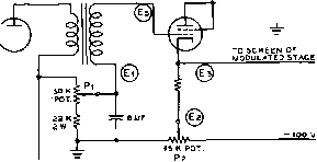 Figure 5 CATHODE-FOLLOWER SCREEN-MODULATION CIRCUIT A detailed discussion of this circuit, which also is represented in figure 4C, is given in the accompanying text. it is not difficult to readjust the amplifier for operation on different bands. Potentiometers Pi (carrier level), and P2 (negative peak level) may be left fixed after a satisfactory adjustment, with the aid of the scope, has once been found. Then when changing bands it is only necessary to adjust excitation until the correct value of grid current is obtained, and then to adjust antenna coupling until correct plate current is obtained. Note that the correct plate current for an efficiency-modulated amplifier is only slightly less than the out-of-resonance plate current of the stage. Hence carrier-level screen voltage must be low so that the out-of-resonance plate current will not be too high, and relatively heavy antenna coupling must be used so that the operating plate current will be near the out-of-resonance value, and so that the operating input will be slightly greater than 1.5 times the rated plate dissipation of the tube or tubes in the stage-Since the carrier efficiency of the stage will be only 35 to 40 per cent, the tubes will be operating with plate dissipation of approximately the rated value without modulation. Speech Clipping in The maximum r-f output the Modulated Stage of an efficiency-modulated stage is limited by the maximum possible plate voltage swing on positive modulation peaks. In the modula-lation circuit of figure 5 the minimum ouфut is limited by the minimum voltage which the screen will reach on a negative modulation peak, as set by potentiometer Pj. Hence the screen-grid-modulated stage, when using the modulator of figure 5, acts effectively as a speech clipper, provided the modulating signal amplitude is not too much more than that value which will accomplish full modulation. With correct adjustments of the operating conditions of the stage it can be made to clip positive and negative modulation peaks symmetrically. However, the inherent peak clipping ability of the stage should not be relied upon as a means of obtaining a large amount of speech compression, since excessive audio distortion and excessive screen current on the modulated stage will result. Characteristics of a An important character-Typical Screen- istic of the screen-modu-Modulated Stage lated Stage, when using the cathode-follower modulator, is that excessive plate voltage on the modulated stage is not required. In fact, full output usually may be obtained with the larger tubes at an operating plate voltage from one-half to two-thirds the maximum rated plate voltage for c-w operation. This desirable condition is the natural result of using a low-impedance source of modulating signal for the stage. As an example of a typical screen-modulated stage, full output of 75 watts of carrier may be obtained from an 813 tube operating with a plate potential of only 1250 volts. No increase in output from the 813 may be obtained by increasing the plate voltage, since the tube may be operated with full rated plate dissipation of 125 watts, with normal plate efficiency for a screen-modulated stage, 37.5 per cent, at the 1250-volt potential. The operating conditions of a screen-modulated 813 stage are as follows: Plate voltage-1250 volts Plate current-160 ma. Plate input~200 watts Grid current-11 ma. Grid bias-110 volts Carrier screen voltage-190 volts Carrier screen current-6 ma. Power output-approx. 75 watts With full 100 per cent modulation the plate current decreases about 2 ma. and the screen current increases about 1 ma.; hence plate, screen, and grid current remain essentially constant with modulation. Referring to figure 5, which was the circuit used as modulator for the 813, (El) measured plus 155 volts, ( E2) measured -50 volts, (E3) measured plus 190 volts, (E4) measured plus 500 volts, and the r.m.s. swing at (E5) for full modulation measured 210 volts, which represents a peak swing of about 296 volts. Due to the high positive voltage, and the large audio swing, on the cathode of the 6L6 (triode connected) modulator tube, it is important that the heater of of this tube be fed from a separate filament transformer or filament winding. Note also that the operating plate-to-cathode voltage on the 6L6 modulator tube does not exceed the З6О-volt rating of the tube, since the operating potential of the cathode is considerably above ground potential. Suppressor-Grid Still another form of effi-Modulation ciency modulation may be obtained by applying the audio modulating signal to the suppressor grid of a pentode Class С r-f amplifier. Basically, suppressor-grid modulation operates in the same general manner as other forms of efficiency modulation; carrier plate circuit efficiency is about 35 per cent, and antenna coupling must be rather tight. However, suppressor-grid modulation has one sizeable disadvantage, in addition to the fact that pentode tubes are not nearly so widely used as beam tetrodes which of course do not have the suppressor element. This disadvantage is that the screen-grid current to a suppressor-grid modulated amplifier is rather high. The high screen current is a natural consequence of the rather high negative bias on the suppressor grid, which reduces the plate-voltage swing and plate current with a resulting increase in the screen current. In tuning a suppressor-grid modulated amplifier, the grid bias, grid current, screen voltage, and plate voltage are about the same as for Class С c-w operation of the stage. But the suppressor grid is biased negatively to a value which reduces the plate-circuit efficiency to about one-half the maximum obtainable from the particular amplifier, with antenna coupling adjusted until the plate input is about 1.5 times the rated plate dissipation of the stage. It is important that the input to the screen grid be measured to make sure that the rated screen dissipation of the tube is not being exceeded. Then the audio signal is applied to the suppressor grid. In the normal application the audio voltage swing on the suppressor will be somewhat greater than the negative bias on the element. Hence suppressor-grid current will flow on modulation peaks, so that the source of audio signal voltage must have good regulation. Tubes suitable for suppressor-grid modulation are: 2E22, 837, 4E27/8001, 5-125, 804 and 8ОЗ. A typical suppressor-grid modulated amplifier is illustrated in figure 6. 15-4 Input Modulation Systems Constant efficiency variable-input modulation systems operate by virtue of the addition 4E27 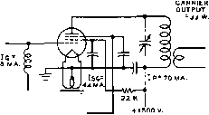 -130 V. 6J5 STEPUP A.F, INPUT О О О о С> PEAK SWING FOR FULL О MODULATION = 210 V. О + 300 V. -21 DV. Figure 6 AMPLIFIER WITH SUPPRESSOR-GRID MODULATION Recommended operating conditions for linear suppressor-grid modulation of a 4Е27/ 257B/800 7 stage are given on the drawing. of external power to the modulated stage to effect the modulation. There are two general classifications that come under this heading; those systems in which the additional power is supplied as audio frequency energy from a modulator, usually called plate modulation systems, and those systems in which the additional power to effect modulation is supplied as direct current from the plate supply. Under the former classification comes Heis-ing modulation (probably the oldest type of modulation to be applied to a continuous carrier), Class В plate modulation, and series modulation. These types of plate modulation are by far the easiest to get into operation, and they give a very good ratio of power input to the modulated stage to power output; 65 to 80 per cent efficiency is the general rule. It is for these two important reasons that these modulation systems, particularly Class В plate modulation, are at present the most popular for communications work. Modulation systems coming under the second classification are of comparatively recent development but have been widely applied to broadcast work. There are quite a few systems in this class. Two of the more widely used are the Doherty linear amplifier, and the Terman-Woodyard high-efficiency grid-modulated amplifier. Both systems operate by virtue of a carrier amplifier and a peak amplifier connected together by electrical quarter-wave lines. They will be described later in this section. Plate Madulation Plate modulation is the application of the audio power to the plate circuit of an r-f amplifier. The r-f amplifier must be operated Class С for this type of modulation in order to obtain a radio-frequency output which changes in exact accordance with the variation in plate voltage. The r-f amplifier is 100 per cent modulated when the peak a-c voltage from the modulator is equal to the d.c, voltage applied to the r-f tube. The positive peaks of audio voltage increase the instantaneous plate voltage on the r-f tube to twice the d-c value, and the negative peaks reduce the voltage to zero. The instantaneous plate current to the r-f stage also varies in accordance with the modulating voltage. The peak alternating current in the output of a modulator must be equal to the d-c plate current of the Class С r-f stage at the point of 100 per cent modulation. This combination of change in audio voltage and current can be most easily referred to in terms of audio power in watts. In a sinusoidally modulated wave, the antenna current increases approximately 22 per cent for 100 per cent modulation with a pure tone input; an r-f meter in the antenna circuit indicates this increase in antenna current. The average power of the r-f wave increases 50 per cent for 100 per cent modulation, the efficiency remaining constant. This indicates that in a plate-modulated radiotelephone transmitter, the audio-frequency channel must supply this additional 50 per cent increase in average power for sine-wave modulation. If the power input to the modulated stage is 100 watts, for example, the average power will increase to 150 watts at 100 per cent modulation, and this additional 50 watts of power must be supplied by the modulator when plate modulation is used. The actual antenna power is a constant percentage of the total value of input power. One of the advantages of plate (or power) modulation is the ease with which proper adjustments can be made in the transmitter. Also, there is less plate loss in the r-f amplifier for a given value of carrier power than with other forms of modulation because the plate efficiency is higher. By properly matching the plate impedance of the r-f tube to the output of the modulator, the ratio of voltage and current swing to d-c voltage and current is automatically obtained. The modulator should have a peak voltage output equal to the average d-c plate voltage on the modulated stage. The modulator should also have a peak power output equal to the d-c plate input power to the modulated stage. The average power output of the modulator will depend upon the type of waveform. If the amplifier is being Heising modulated by a Class A stage, the modulator must have an average MODULATED CLASS С R.F. AMPLIFIER CLWSC AMPLIFIER 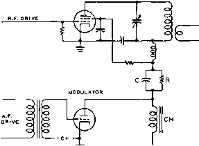 Figure 7 HEISING PLATE MODULATION This type of madulation was the first form of plate madulattort. It is sometimes known as constont current modulation. Because of the effective 1:1 ratio of the coupling choke, it is impossible to obtain 100 per cent madulation unless the plate voltage to the modulated stage is dropped slightly by resistor R. The capacitor С merely bypasses the audio around R, so that the full a-f output voltage of the modulator is Impressed on the Class С stage. 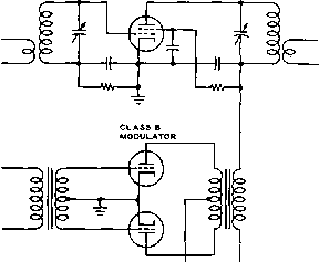 MOO.+B R.F. + B Figure 8 CLASS В PLATE MODULATION This type of modulation Is the most flexible in that the loading adjustment can be made in a short period of time and without elaborate test equipment after a chonge in operoting freqfueney of the Class С amplifier has been made. power output capability of one-half the input to the Class С stage. If the modulator is a Class В audio amplifier, the average power required of it may vary from one-quarter to more than one-half the Class С input depending upon the waveform. However, the peak power output of any modulator must be equal to the Class С input to be modulated. Heising Heising modulation is the oldest Modulation system of plate modulation, and usually consists of a Class Л audio amplifier coupled to the r-f amplifier by means of a modulation choke coil, as shown in figure 7. The d.c. plate voltage and plate current in the r-f amplifier must be adjusted to a value which will cause the plate impedance to match the output of the modulator, since the modulation choke gives a 1-to-l coupling ratio. A series resistor, by-passed for audio frequencies by means of a capacitor, must be connected in series with the plate of the r-f amplifier to obtain modulation up to 100 per cent. The peak output voltage of a Class A amplifier does not reach a value equal to the d-c voltage £фplied to the amplifier and, consequently, the d-c plate voltage impressed across the r-f tube must be reduced to a value equal to the maximum avEiilable a-c peak voltage if 100% modulation is to be obtained. A higher degree of distortion can be tolerated in low-power emergency phone transmitters which use a pentode modulator tube, and the series resistor and by-pass capacitor are usually omitted in such transmitters. Class В High-level Class В plate Plate Modulation modulation is the least expensive method of plate modulation. Figure 8 shows a conventional Class В plate-modulated Class С amplifier. The statement that the modulator output power must be one-half the Class С input for 100 per cent modulation is correct only if the waveform of the modulating power is a sine tvave. Where the modulator waveform is undipped speech, the average modulator power for 100 per cent modulation is considerably less than one-half the Class С input. Power Relations in Speech Waveforms It has been determined experimentally that the ratio of peak to average power in a speech waveform is approximately 4 to 1 as contrasted to a ratio of 2 to 1 in a sine wave. This is due to the high harmonic content of such a waveform, and to the fact that this high harmonic content manifests itself by making the wave unsymmetrical and causing sharp peaks or fingers of high energy content to appear. Thus for undipped speech, the average modulator plate current, plate dissipation, and power output are approximately one-half the sine wave values for a given peak output power. Both peak power and average power are necessarily associated with waveform. Peak power is just what the name implies; the power at the peak of a wave. Peak power, although of the utmost importance in modulation, is of no great significance in a-c power work, except insofar as the average power may be determined from the peak value of a known wave form. There is no time element implied in the definition of peak power; peak power may be instantaneous-and for this reason average power, which is definitely associated with time, is the important factor in plate dissipation. It is possible that the peak power of a given waveform be several times the average value; for a sine wave, the peak power is twice the average value, and for undipped speech the peak power is approximately four times the average value. For 100 per cent modulation, the peak (instantaneous) audio power must equal the Class С input, although the average power for this value of peak varies widely depending upon the modulator waveform, being greater than 50 per cent for speech that has been clipped and filtered, 50 per cent for a sine wave, and about 25 per cent for typical undipped speech tones. Madulation The modulation transformer is Tronsformer a device for matching the load Calculations impedance of the Class С am plifier to the recommended load impedance of the Class В modulator tubes. Modulation transformers inrended for communications work are usually designed to carry the Class С plate current through their secondary windings, as shown in figure 8-The manufacturers ratings should be consulted to insure that the d-c plate current passed through the secondary winding does nor exceed the maximum rating. A detailed discussion of the method of making modulation transformer calculations has been given in Chapter Six. However, to emphasize the method of making the calculation, an additional example will be given. Suppose we take the case of a Class С amplifier operating at a plate voltage of 2000 with 225 ma. of plate current. This amplifier would present a load resistance of 2000 divided by 0.225 amperes or 8888 ohms. The plate power input would be 2000 times 0.225 or 450 watts. By reference to Chapter Six we see that a pair of 811 tubes operating at 1500 plate volts will deliver 225 watts of audio output. The plate-to-plate load resistance for these tubes under the specified operating conditions is 18,000 ohms. Hence our problem is to match the Class С amplifier load resistance of 8888 ohms to the 18,000-ohm load resistance required by the modulator tubes. A 200-to-300 watt modulation transformer will be required for the job. If the taps on the transformer are given in terms of impedances it will only be necessary to connect the secondary for 8888 ohms (or a value approximately equal to this such as 9000 ohms) and the primary for 18,000 ohms. If it is necessary to determine the proper turns ratio required of the transformer it can be determined in the following manner. The square root of the impedance ratio is equal to the turns ratio, hence: 8888 = yJ 0.494 = 0.703 18000 The transformer must have a turns ratio of approximately l-to-0.7 step down, total primary to total secondary. The greater number of turns always goes with the higher impedance, and vice versa. Plate-ond-Screen When only the plate of a Modulation screen-grid tube is modu- lated, it is impossible to obtain high-percentage linear modulation under ordinary conditions. The plate current of such a stage is not linear with plate voltage. However, if the screen is modulated simultaneously with the plate, the instantaneous screen volr-age drops in proportion to the drop in the plate voltage, and linear modulation can then be obtained. Four satisfactory circuits for accomplishing combined plate and screen modulation are shown in figure 9- The screen r-f by-pass capacitor C2, should not have a greater value than 0.005 fxfd., preferably not larger than 0. OOl /ifd. It should be large enough to bypass effectively all r-f voltage without short-circuiting high-frequency audio voltages. The plate by-pass capacitor can be of any value from 0.002 /fd. to 0. 005 /ifd. The screen-dropping resistor, Ri should reduce the applied high voltage to the value specified for operating the particular tube in the circuit. Capacitor Ci is seldom required yet some tubes may require this capacitor in order to keep C2 from attenuating the high frequencies. Different values between ,0002 and .002 yiiA. should be tried for best results. Figure 9C shows another method which uses a third winding on the modulation transformer, through which the screen-grid is connected to 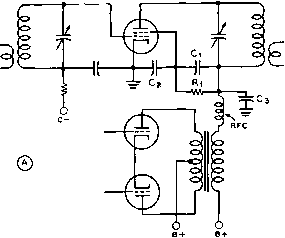 7Г  © о о о о В+ S.G. В+ 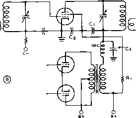 о о о ©  о LO О о о S rfc о о о о о 6 о B+S.C. в+ о о о о Figure 9 PLATE MODULATION OF A BEAM TETRODE OR SCREEN-GRID TUBE These alternative arrangements for plate modalatton of tetrodes or pentodes are discussed In detail in the text. The arrangements shown a* (B) or (D) are recommended for most applications. a low-voltage power supply. The ratio of turns between the two output windings depends upon the type of screen-grid tube which is being modulated. Normally it will be such that the screen voltage is being modulated 60 per cent when the plate voltage is receiving 100 per cent modulation. If the screen voltage is derived from a dropping resistor ( not a divider) that is bypassed for r.f. but not a.f., it is possible to secure quite good modulation by applying modulation only to the plate. Under these conditions, the screen tends to modulate itself, the screen voltage varying over the audio cycle as a result of the screen impedance increasing with plate voltage, and decreasing with a decrease in plate voltage. This circuit arrangement is illustrated in figure 9B. A similar application of this principle is shown in figure 9D. In this case the screen voltage is fed directly from a low-voltage supply of the proper potential through a choke L. A conventional filter choke having an inductance from 10 to 20 henries will be satisfactory for L. To afford protection of the tube when plate voltage is not applied but screen voltage is supplied from the exciter power supply, when using the arrangement of figure 9D, a resistor of 3000 to 10, ООО ohms can be connected in series with the choke L. In this case the screen supply voltage should be at least 14 times as much as is required tor actual screen voltage, and the value of resistor is chosen such that with normal screen current the drop through the resistor and choke will be such that normal screen voltage will be applied to the tube. When the plate voltage is removed the screen current will increase greatly and the drop through resistor R will increase to such a value that the screen voltage will be lowered to the point where the screen dissipation on the tube will not be exceeded. However, the supply voltage and value of resistor R must be chosen carefully so that the maximum rated screen dissipation cannot be exceeded. The maximum possible screen dissipation using this arrangement is equal to: W = EV4R where E is the screen supply voltage and R is the combined resistance of the resistor in figure 9D and the d-c resistance of the choke L. It is wise, when using this arrangement to check, using the above formula, to see that the value of W obtained is less than the maximum rated screen dissipation of the tube or tubes used in the modulated stage. This same system can of course also be used in figuring the screen supply circuit of a pentode or tetrode amplifier stage where modulation is not to be applied. The modulation transformer for plate-and-screen-modulation, when utilizing a dropping resistor as shown in figure 9A, is similar to the type of transformer used for any plate modulated phone. The combined screen and plate current is divided into the plate voltage in order to obtain the Class С amplifier load impedance. The peak audio power required to obtain 100 per cent modulation is equal to the d-c power input to the screen, screen resistor, and plate of the modulated r-f stage. 15-5 Cathode Modulation Cathode modulation offers a workable compromise between the good plate efficiency but expensive modulator of high-level plate modulation, and the poor plate efficiency but inexpensive modulator of grid modulation. Cathode modulation consists essentially of an admixture of the two. The efficiency of the average well-designed pi ate-modulated transmitter is in the vicinity of 75 to 80 per cent, with a compromise perhaps at 77-5 per cent. On the other hand, the efficiency of a good grid-modulated transmitter may run from 28 to maybe 40 per cent, with the average falling at about 34 per cent. Now since cathode modulation consists of simultaneous grid and plate modulation, in phase with each other, we can theoretically obtain any efficiency from about 34 to 77.5 per cent from our cathode-modidated stage, depending upon the relative percentages of grid and plate modulation. Since the system is a compromise between the two fundamental modulation arrangements, a value of efficiency approximately half way between the two would seem to be the best compromise. Experience has proved this to be the case. A compromise efficiency of about 56.5 per cent, roughly half way between the two limits, has proved to be optimum. Calculation has shown that this value of efficiency can be obtained from a cathode-modulated amplifier when the audio-frequency modulating power is approximately 20 per cent of the d-c input to the cathode-modulated stage. An Economical Series cathode modulation is Series Cathode ideally suited as an economi-Modulator cal modiUating arrangement for a high-power triode c-w transmitter. The modulator can be constructed quite compactly and for a minimum component cost since no power supply is required for it. When it is desired to change over from c-w to phone, it is only necessary to cut the series modulator into the cathode return circuit of the c-w amplifier stage. The plate voltage for the modulator tubes and for the speech amplifier is taken from the cathode voltage drop of the modulated stage across the modulator unit. Figure 10 shows the circuit of such a modulator, designed to cathode modulate a Class С amplifier using push-pull 810 tubes, running at a supply voltage of 2500, and with a plate input of 660 watts. The modulated stage runs at about 50% efficiency, giving a power output of nearly 350 watts, fully modulated. The voltage drop across the cathode modulator is 400 volts, allowing a net plate to cathode voltage of 2100 volts on the final amplifier. The plate current of the 810s should be about 330 ma., and the grid current should be approximately 40 ma., making the total cathode current of the modulated stage 370 ma. Four parallel 6L6 modulator tubes can pass this amount of plate current without difficulty. It must be remembered that the voltage drop across the cathode modulator is also the cathode bias of the modulated stage. In most cases, no extra grid bias is necessary. If a bias supply is used for c-w operation, it may be removed for cathode modulation, as shown in figure 11. With low-mu triodes, some extra grid bias (over and above that amount supplied by the cathode modulator) may be needed to achieve proper linearity of the modulated stage. In any case, proper operation of a cathode modulated stage should be determined by examining the modulated output waveform of the stage on an oscilloscope. Excitotion The r-f driver for a cathode-modulated stage shoidd have about 6AU6 6AU6 - SIM 7 IM 7  TO CATHODE modulated stage  ALL RESISTORS O.S WATT UNLESS OTHERWISE NOTED. ALL CAPACITORS IN JUF UNLESS OTHERWISE NOTED. CAUTION -FILAMENTS OF 6L6 TUBES MUST BE AT OPERATING TEMPERATURE BEFORE PLATE VOLTAGE IS APPLIED TO MODULATED AMPLIFIER. Figure 10 SERIES CATHODE MODULATOR FOR A HIGH-POWERED TRIODE R-F AMPLIFIER the same power оифиг capabilities as would be required to drive a c-w amplifier to the same input as it is desired to drive the cathode-modulated stage. However, some form of excitation control should be available since the amount of excitation power has a direct bearing on the linearity of a cathode-modulated amplifier stage. If link coupling is used between the driver and the modulated stage, variation in the amount of link coupling will afford apnple excitation variation. If much less than 40% plate modulation is employed, the stage begins to resemble a grid-bias modulated stage, and the necessity for good r-f regulation will apply. Cathode Modulation af Tetrodes Cathode modulation has not proved too satisfactory for use with beam tetrode tubes. This is a result of the small excitation and grid swing requirements for such tubes, plus the fact that some means for holding the screen voltage at the potential of the cathode as far as audio is concerned is usually necessary. Because of these factors, cathode modulation is not recommended for use with tetrode r-f amplifiers. 15-6 The Doherty and the Termon-Woodyard Modulated Amplifiers These two amplifiers will be described together since they operate upon very similar principles. Figure 12 shows a greatly simplified schematic diagram of the operation of both types. Both systems operate by virtue of a carrier tube (Vi in both figures 12 and 13) which supplies the unmodulated carrier, and whose output is reduced to supply negative peaks, and a peak tube (Vj) whose function is to supply approximately half the positive peak of the modulation cycle and whose additional function is to lower the load impedance on the carrier tube so that it will be able to supply the other half of the positive peak of the modulation cycle. The peak tube is enabled to increase the output of the carrier tube by virtue of an impedance inverting line between the plate circuits of the two tubes. This line is designed to have a characteristic impedance of one-half the value of load into which the carrier tube operates under the carrier conditions. Then a load of one-half the characteristic impedance of the quarter-wave line is coupled into the output. By experience with quarter-wave lines in antenna-matching circuits we know that such a line will vary the impedance at one end of the line in such a manner that the geometric mean between the two terminal impedances will be equal to the characteristic impedance of the line. Thus, if we have a value of load of one-half the characteristic impedance of the line at one end, the other end of the line will present a value of twice the characteristic impedance of the lines to the carrier tube Vi. This is the situation that exists under the carrier conditions when the peak tube merely floats across the load end of the line and contributes no power. Then as a positive peak of modulation comes along, the peak tube starts to contribute power to the load until at the peak of the modulation cycle it is contributing enough power so that the impedance at the load end of the line is equal to R, instead of HANDBOOK Doherty Amplifier 299 R.F. AMPLIFIER 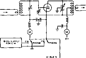 MIC 6AUe SAUe .CATHODE MODULATOR Figure 11 CATHODE MODULATOR INSTALLATION SHOWING PHONE-CW. TRANSFER SWITCH the R/2 that is presented under the carrier conditions. This is true because at a positive modulation peak (since it is delivering full power) the peak tube subtracts a negative resistance of R/2 from the load end of the line. Now, since under the peak condition of modulation the load end of the line is terminated in R ohms instead of R/2, the impedance at the carrier-tube will be reduced from 2R ohms to R ohms. This again is due ro the impedance inverting action of the line. Since the load resistance on the carrier tube has been reduced to half the carrier value, its оифШ at the peak of the modulation cycle will be doubled. Thus we have the necessary condition for a 100 per cent modulation peak; the amplifier will deliver four times as much power as it does under the carrier conditions. On negative modulation peaks the peak tube does not contribute; the оифи1 of the carrier tube is reduced until on a 100 per cent negative peak its output is zero. The Electrical While an electrical quarter-Quarter-Wove wave line (consisting of a pi Line network with the inductance and capacitance units having a reactance equal to the characteristic impedance of the line) does have the desired impedance-inverting effect, it also has the undesirable effect of introducing a 90° phase shift across such a line. If the shunt elements are capacitances, the phase shift across the line lags by 90°; if they are inductances, the phase shift leads by 90* . Since there is an un- -JX=Rg о о JX=Re О о ЧТУ ELECTRICAL V* LINE Z0= R JX=R l  Figure 12 DIAGRAMMATIC REPRESENTATION OF THE DOHERTY LINEAR desirable phase shifr of 90° between the plate circuits of the carrier and peak tubes, an equal and opposite phase shift must be introduced in the exciting voltage to the grid circuits of the two tubes so that the resultant output in the plate circuit will be in phase. This additional phase shift has been indicated in figure 12 and a method of obtaining it has been shown in figure 13. Comparison Between The difference between Linear and the Doherty linear Grid Modulator plifier and the Terman- Woodyard grid-modulated amplifier is the same as the difference between any linear and grid-modulated stages. Modulated r.f.is applied to the grid circuit of the Doherty linear amplifier with the carrier tube biased to cutoff and the peak tube biased to the point where it draws substantially zero plate current at the carrier condition. In the Terman-Woodyard grid-modulated amplifier the carrier tube runs Class С with comparatively high bias and high plate efficiency, while the peak tube again is biased so that it draws almost no plate current. Unmodulated r.f. is applied to the grid circuits of the two tubes and the modulating voltage is inserted in series with the fixed bias voltages. From one-half to two-thirds as much audio voltage is required at the grid of the peak tube as is required at the grid of the carrier tube. Operating The resting carrier efficiency of Efficiencies the grid-modulated amplifier may run as high as is obtainable in any Class С stage, 80 per cent or better. The resting carrier efficiency of the linear will be about as good as is obtainable in any Class В amplifier, 60 to 70 per cent. The overall efficiency of the bias-modulated amplifier at 100 per cent modulation will run about 75 per cent; of the linear, about 60 per cent. In figure 13 the plate tank circuits are detuned enough to give an effect equivalent to the shunt elements of the quarter-wave line of figure 12. At resonance, the coils L, and L2 in the grid circuits of the two tubes have EXCITATION о о о о 7Г 7 BIAS V 2- О о о о о  /Г -о о l3 0 -о 3 § Ь>12т. Figure 13 SIMPLIFIED SCHEMATIC OF A HIGH EFFICIENCY AMPLIFIER The basic system, comprising a carrier tube and a peak tube interconnected by lumped-const ant quarter-wave lines, is the same for either grid-bias modulation or for use as a linear amplifier of a modulated wave. each an inductive reactance equal to the capacitive reactance of the capacitor Q. Thus we have the effect of a pi network consisting of shunt inductances and series capacitance. In the plate circuit we want a phase shift of the same magnitude but in the opposite direction; so our series element is the inductance L3 whose reactance is equal to the characteristic impedance desired of the network. Then the plate tank capacitors of the two tubes C2 and C3 are increased an amount past resonance, so that they have a capacitive reactance equal to the inductive reactance of the coil L3. It is quite important that there be no coupling between the inductors. Although both these types of amplifiers are highly efficient and require no high-level audio equipment, they are difficult to adjust-particularly so on the higher frequencies-and it would be an extremely difficult problem to design a multiband transmitter employing the circuit. However, the grid-bias modulation system has advantages for the high-power transmitter which will be operated on a single frequency band. Other High-Efficiency Many other high-efficien-Modulotion Systems cy modulation systems have beendescribed since about 1936. The majority of these, however have received little application either by commercial interests or by amateurs. In most cases the circuits are difficult to adjust, or they have Other undesirable features which make their use impracticable alongside the more conventional modulation systems. Nearly all these circuits have been published in the I.R.E. Proceedings and the interested reader can refer to them in back copies of that journal. 15-7 Speech Clipping Speech waveforms are characterized by frequently recurring high-intensity peaks of very short duration. These peaks will cause over-modulation if the average level of modulation on loud syllables exceeds approximately 30 per cent. Careful checking into the nature of speech sounds has revealed that these high-intensity peaks are due primarily to the vowel sounds. Further research has revealed that the vowel sounds add little to intelligibility, the major contribution to intelligibility coming from the consonant sounds such as v, b, k, s, t, and I. Measurements have shown that the power contained in these consonant sounds may be down 30 db or more from the energy in the vowel sounds in the same speech passage. Obviously, then, if we can increase the relative energy content of the consonant sounds with respect to the vowel sounds it will be possible to understand a signal modulated with such a waveform in the presence of a much higher level of background noise and interference. Experiment has shown that it is possible to accomplish this desirable result simply by cutting off or clipping the high-intensity peaks and thus building up in a relative manner the effective level of the weaker sounds. Such clipping theoretically can be accomplished simply by increasing the gain of the speech amplifier until the average level of modulation on loud syllables approaches 90 per cent. This is equivalent to increasing the speech power of the consonant sounds by about 10 times or, conversely, we can say that 10 db of clipping has been applied to the voice wave. However, the clipping when accomplished in this manner will produce higher order sidebands known as splatter, and the transmitted signal would occupy a relatively tremendous slice of spectrum. So another method of accomplishing the desirable effects of clipping must be employed. A considerable reduction in the amount of splatter caused by a moderate increase in the gain of the speech amplifier can be obtained by poling the signal from the speech amplifier to the transmitter such that the high-intensity peaks occur on upward or positive modulation. Overloading on positive modulation peaks produces less splatter than the negative-peak clipping which occurs with overloading on the 1 ... 26 27 28 29 30 31 32 ... 80 |
|
© 2026 AutoElektrix.ru
Частичное копирование материалов разрешено при условии активной ссылки |