 |
 |
 |
| Главная Журналы Популярное Audi - почему их так назвали? Как появилась марка Bmw? Откуда появился Lexus? Достижения и устремления Mercedes-Benz Первые модели Chevrolet Электромобиль Nissan Leaf |
Главная » Журналы » Simple coaxial reflectometer 1 ... 27 28 29 30 31 32 33 ... 80 HANDBOOK Speech Clipping 301 Figure 14 SPEECH-WAVEFORM AMPLITUDE MODULATION Showing fbe effect of using the proper polarity of a speech wave for modulating a transmitter. (A) shows the effect of proper speech polarity on a transmitter having an upward modulation capability of greater than 100 per cent. (B) shows the effect of using proper speech polarity on a transmitter having an upward modulation capability of only 100 per cent. Both these conditions will give a clean signal without objectionable splatter. (C) shows the effect of tbe use of improper speech polarity. This condition will cause serious splatter due to negative-peak clipping in the modulated-amplifier stage. ® ® 100% posooulajion 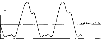 100 ЧЬ MEG. MODULATION 100¥o POSMOpUL AT I ON 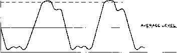 ЮОЧЬ NES MODULATION 100 h POS. MODULATION 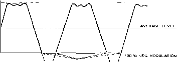 , , NEGATIVE PEAK CLIPPING negative peaks of modulation. This aspect of the problem has been discussed in more detail in the section on Speech Waveform Dissymmetry earlier in this chapter. The effect of feeding the proper speech polarity from the speech amplifier is shown in figure 14. A much more desirable and effective method of obtaining speech clipping is actually to employ a clipper circuit in the earlier stages of the speech amplifier, and then to filter out the objectionable distortion components by means of a sharp low-pass filter having a cut-off frequency of approximately 3000 cycles. Tests on с Upper-filter speech systems have shown that 6 db of clipping on voice is just noticeable, 12 db of clipping is quite acceptable, and values of clipping from 20 to 25 db are tolerable under such conditions that a high degree of clipping is necessary to get through heavy QRM or QRN. A signal with 12 db of clipping doesnt sound quite natural but it is not unpleasant to listen to and is much more readable than an undipped signal in the presence of strong interference. The use of a clipper-filter in the speech amplifier, to be completely effective, requires that phase shift between the clipper-filter stage and the final modulated amplifier be kept to a minimum. However, if there is phase shift after the clipper-filter the system does not completely break down. The presence of phase shift merely requires that the audio gain following the clipper-filter be reduced to the point where the cant applied to the clipped speech waves still cannot cause overmodulation. This effect is illustrated in figures 15 and 16. The cant appearing on the tops of the square waves leaving the clipper-filter centers about the clipping level. Hence, as the frequency being passed through the system is lowered, the amount by which the peak of the canted wave exceeds the clipping level is increased. Phose Shift In a normal transmitter having a Correction moderate amount of phase shift the cant applied to the tops of the waves will cause overmodulation on frequencies below those for which the gain following the clipper-filter has been adjusted unless remedial steps have been taken. The following steps are advised: (1) Introduce bass suppression into the speech amplifier ahead of the clipper-filter. (2) Improve the low-frequency response characteristic insofar as it is possible in the © 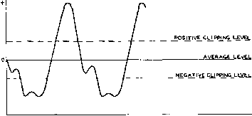 INCOMiNG SPEECH WAVE 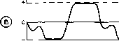 AVERASE LEVEL CLIPPED AND FILTERED SPEECH WAVE 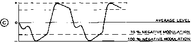 Figur* ts ACTION OF A CLIPPER-FILTER ON A SPEECH WAVE The drawing (A) shows fhe mcom-ing speech wove ЬсАэге if reaches fhe dipper stage. (B) shows the TOsm\cuppiNG LEVEL oufpuf of the clipper-filter, Illustrating the manner in which the peaks are clipped and then the sharp edges of the clipped wave removed by the filter. (C) shows the effect of phase shift in the stages following the clipper-filter. (C) also shows the manner in which the transmitter may be adjusted for 100 per cent modulation of the canted peaks of the wave, the sloplrtg top of the wave reaching about 70 per cent modulation. NESATIVE CLIPPING LEVEL .100 POSITIVE MOOULATION 70 ЧЬ POSITIVE MODULATION MODULATED WAVE AFTER UNDERGOING PHASE SHIFT Stages jolloiving the clipper-filter. Feeding the plate current to the final amplifier through a choke rather than through the secondary of the modulation transformer will help materially. Even with the normal amount of improvement which can be attained through the steps mentioned above there will still be an amount of wave cant which must be compensated in some manner. This compensation can be done in either of two ways. The first and simpler way is as follows: (1) Adjust the speech gain ahead of the clipper-filter until with normal talking into the microphone the distortion being introduced by the clipper-filter circuit is quite apparent but not objectionable. This amount of distortion will be apparent to the normal listener when 10 to 15 db of clipping is taking place. ( 2) Tune a selective communications receiver about 15 kc. to one side or the other of the frequency being transmitted. Use a short antenna or no antenna at all on the receiver so that the transmitter is not blocking the receiver. (3) Again with the normal talking into the microphone adjust the gain follotving the clipper-filter to the point where the sideband splatter is being heard, and then slightly back off the gain after the clipper-filter until the splatter disappears. If the phase shift in the transmitter or modulator is not excessive the adjustment procedure given above will allow a clean signal to be radiated regardless of any reasonable voice level being fed into the microphone. If a cathode-ray oscilloscope is available the modulated envelope of the transmitter should be checked with 30 to 70 cycle sawtooth waves on the horizontal axis. If the upper half of the envelope appears in general the same as the drawing of figure 15C, all is well and phase-shift is not excessive. However, if much more slope appears on the tops of the waves than is illustrated in this figure, it will be well to apply the second step in compensation in order to insure that sideband splatter cannot take place and to afford a still higher average percentage of modulation. This second step consists of the addition of a high-level splatter suppressor such as is illustrated in figure 17. HANDBOOK Splatter Suppression 303 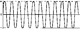 3000 0, WAVE 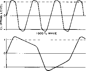 300 \j WAVE Figure 16 ILLUSTRATING THE EFFECT OF PHASE SHIFT AND FILTERED WAVES OF DIFFERENT FREQUENCY Skefcb (A) shows the effect of a clipper and a filter having a cutoff of about 3500 eyelet on a wave of 3000 cycles. Note that no harmonics are present In the wove so that phase shift following the clipper-filter will have no significant effect on the shape of the wave. (B) and (C) show the effect of phase shift on waves well below the cutoff frequency of the filter. Note that the cant placed upon the top of the wave causes the peak value to rise higher and higher above the clipping level as the frequency is lowered. It is for this reason that boss suppression before the clipper stage Is desirable. Improved low-frequency response following the clipper-filter will reduce the phase shift and therefore the canting of the wave at the lower voice frequencies. The use of a high-level splatter suppressor after a clipper-filter system will afford the result shown in figure 18 since such a device will not permit the negative-peak clipping which the wave cant caused by audio-system phase shift can produce. The high-level splatter suppressor operates by virtue of the fact that it will not permit the plate voltage on the modulated amplifier to go completely to zero regardless of the incoming signal amplitude. MODULATOR 5R4GY. 1616 в36 О О о о о Сз TC4 / FIL. TRANS, .INSULATED FOR H.V. PLATE- MODULATED CLASS-C AMPLIFIER 7500-to ООО OHMS LOAD +b R,F, FINAL Figure 17 HIGH-LEVEL SPLATTER SUPPRESSOR This circuit is effective in reducing splatter caused by negative-peak clipping in the modulated amplifier stage. The use of a two-section filter as shown is recommended, although either a single m-derived or a con-stant-k section may be used for greater economy. Suitable chokes, along with recommended capacitor values, are available from several manufacturers. Hence negative-peak clipping with its attendant splatter cannot take place. Such a device can, of course, also be used in a transmitter which does not incorporate a clipper-filter system. However, the full increase in average modulation level without serious distortion, afforded by the clipper-filter system, will not be obtained. A word of caution should be noted at this time in the case of tetrode final modulated amplifier stages which afford screen voltage modulation by virtue of a tap or a separate winding on the modulation transformer such as is shown in figure 9C of this chapter. If such a system of modulation is in use, the high-level splatter suppressor shown in figure 17 will not operate satisfactorily since negative-peak clipping in the stage can take place when the screen voltage goes too low. Clipper Circuits Two effective low-level clipper-filter circuits are shown in figures 19 and 20. The circuit of figure 19 employs a 6J6 double triode as a clipper, each half of the 6J6 clipping one side of the .m-pressed waveform. The optimum level at which the clipping operation begins is set by the value of the cathode resistor. A maximum of 12 to 14 db of clipping may be used with this circuit, which means that an extra 12 to 14 db of speech gain must precede the clipper. For a peak оифиг of 8 volts from the clipper-filter, a peak audio signal of about 40 volts must be impressed upon the clipper input circuit. The 6C4 speech amplifier stage must therefore be considered as a part of the clipper circuit as 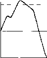 100 * POS. MODULATION ZERO AXIS 100 ЧЬ NEG. MODULATION SPLATTER-CAUSING NEGATIVE OVERMODULATION PEAK CUT OFF BY HIGH-LEVEL SPLATTER SUPPRESSOR. Figure 18 ACTION OF HIGH-LEVEL SPLATTER SUPPRESSOR A high-level splatter suppressor may he used in a transmitter without a clipper-filter to reduce negative-peak clipping, or such a unit may he used following a clipper-filter to allow a higher overage modulation level by eliminating the negative-peak dipping which the wave-cant caused by phase shift might produce. it compensates for the 12 to 14 db loss of gain incurred in the clipping process. A simple low-pass filter made up of a 20 henry a.c. - d.c replacement type filter choke and two mica condensers follows the 6J6 clipper. This filter is designed for a cutoff frequency of about 3500 cycles when operating into a load impedance of Уг megohm. The output level of 8 volts peak is ample to drive a triode speech amplifier stage, such as a 6C4 or 6J5. A 6AL5 double diode series clipper is employed in the circuit of figure 20, and a commercially made low-pass filter is used to give somewhat better high frequency cutoff characteristics. A double triode is employed as a speech amplifier ahead of the clipper circuit. The actual performance of either circuit is about the same. To eliminate higher order products that may be generated in the stages following the clipper-filter, it is wise to follow the modulator with a high-level filter, as shown in figure 21. Clipper Adjustment These clipper circuits have two adjustments: Adjust Gain and Adjust Clipping. The Adj. Gain control determines the modulation level of the transmitter. This control should be set so that over-modulation of the transmitter is impossible, regardless of the amount of clipping used. Once the Adj. Gain control has been roughly set, the Adj. Clip, control may be used to set the modulation level to any percentage below 100%. As the modulation level is decreased, more and more clipping is introduced into the circuit, until a full 12 db of clipping is used. This means that the Adj. Gain control may be advanced some 12 db past the point where the clipping action started. Clipping action should start at 85% to 90% modulation when a sine wave is used for circuit adjustment puфoses. High-Level Even though we may have cut off Filters all frequencies above 3000 or 3500 cycles through the use of a filter system such as is shown in the circuits of figures 19 and 20, higher frequencies may again be introduced into the modulated wave by distortion in stages following the speech amplifier. Harmonics of the incoming audio frequencies may be generated in the driver stage for the modulator; they may be generated in the plate circuit of the modulator; or they may be generated by non-linearity in the modulated amplifier itself. ATAL MIC. Dv-w 6AU6 ADJUST CLIP., 20 H (STANCOR C-ISIS) 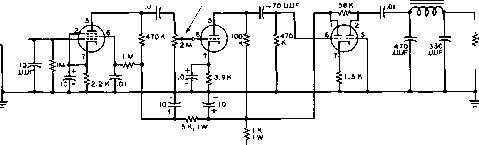 -ADJUST GAIN TO NEXT GRID PEAK OUTPUT APPPOK. BV. MAX. WITH UDB OF CLIPPING. ALL RESISTORS O.S WATT UNLESS OTHERWISE MARKED. ALL CAPACITORS IN ZIP UNLESS OTHERWISE NOTED. Figure 19 CLIPPER FILTER USING 6J6 DOUBLE TRIODE STAGE HANDBOOK Splatter Suppression 305 12AK7 /iDJUST GAIN 6AL5 CHICAGO TRANS. LPF-2 FILTER 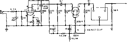 TO NEXT GRID PEAK OUTPUT APPROX. 5 V MAX WITH /г OS OFCLIPPWS ALL RESISTORS O.i WATT UNLESS OTHERWISE MARKED. ALL CAPACITORS IH JJF UNLESS OTHERWISE MARKED. Figure 20 CLIPPER FILTER USING 6AL5 STAGE Regardless of the poitit in the system following the speech amplifier where the high audio frequencies may be generated, these frequencies can still cause a broad signal to be transmitted even though all frequencies above 3000 or 3500 cycles have been cut off in the speech amplifier. The effects of distortion in the audio system following the speech amplifier can be eliminated quite effectively through the use of a post-modulator filter. Such a filter must be used between the modulator plate circuit and the r-f amplifier which is being modulated. This filter may take three general forms in a normal case of a Class С amplifier plate modulated by a Class В modulator. The best method is to use a high level low-pass filter as CLASS С AMPLIFIER 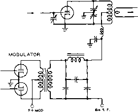 Figure 21 ADDITIONAL HIGH-LEVEL LOW-PASS FILTER TO FOLLOW MODULATOR WHEN A LOW-LEVEL CLIPPER FILTER IS USED 5u/fabfe choke, along with recommended capacitor values, is available from several manufacturers. shown in figure 21 and discussed previously. Another method which will give excellent results in some cases and poor results in others, dependent upon the characteristics of the modulation transformer, is to build out the modulation transformer into a filter section. This is accomplished as shown in figure 22 by placing mica capacitors of the correct value across the primary and secondary of the modulation transformer. The proper values for the capaci- CLASS С STAGE О о о о 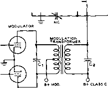 -о -о Figure 22 BUILDING-OUT THE MODULATION TRANSFORMER Th/s expedient utilizes the leakage reactance of the modulation transformer in conjunction with the capacitors shown to make up a single-section low-pass filter. In order to determine exact values for and Cj plus Сз, it is necessary to use a measurement setup such as is shown in figure 23. However, experiment has shown in the case of a number of cammercially available modulation transformers that a value for С/ of 0.002-lJ.fd, and Сг plus C3 af 0.004-lifd. will give satis-factory results. AUDIO OSCILLAroR ЛААг  V) о-кз
Figure 23 TEST SETUP FOR BUILDING-OUT MODULATION TRANSFORMER Through the use of a text setup such as is shown and the method described in the text it is possible to determine the correct values for a specified filter characteristic in the built-aut modulation transformer. tors Q and C2 must, in the ideal case, be determined by trial and error. Experiment with a number of modulators has shown, however, that if a 0.002 fxfd, capacitor is used for and if the sum of C2 and Q is made 0. 004 /ufd. (0.002 [ifd, for C2 and 0. 002 for C3) the ideal condition of cutoff above ЗООО cycles will be approached in most cases with the multiple-match type of modulation transformer. If it is desired to determine the optimum values of the capacitors across the transformer this can be determined in several ways, all of which require the use of a calibrated audio oscillator. One way is diagrammed in figure 23. The series resistors and R2 should each be equal to 14 the value of the recommended plate-to-plate load resistance for the Class В modulator tubes. Resistor R3 should be equal to the value of load resistance which the Class С modulated stage will present to the modulator. The meter V can be any type of a-c voltmeter. The indicating instrument on the secondary of the transformer can be either a cathode-ray oscilloscope or a high-impedance a-c voltmeter of the vacuum-tube or rectifier type. With a set-up as shown in figure 23 a plot of output voltage against frequency is made, at all times keeping the voltage across V constant, using various values of capacitance for Cl and C2 plus C3. When the proper values of capacitance have been determined which give substantially constant output up to about 3000 or 3500 cycles and decreasing output at all frequencies above, high-voltage mica capacitors can be substituted if receiving types were used in the tests and the transformer connected to the modulator and Class С amplifier. With the transformer reconnected in the transmitter a check of the modulated-wave output of the transmitter should be made using an audio oscillator as signal generator and an oscilloscope coupled to the transmitter output. With an input signal amplitude fed to the speech 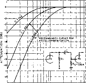 гоо 300 500 TOO (ООО 2000 3000 SDOO frequency (cps) Figure 24 BASE ATTENUATION CHART Frequency attenuation caused by various values of coupling copoc/for with a grid resistor of O.S megohm in the following stage (RC > RU amplifier of such amplitude that limiting does not take place, a substantially clean sine wave should be obtained on the carrier of the transmitter at all input frequencies up to the cutoff frequency of the filter system in the speech amplifier and of the filter which includes the modulation transformer. Above rhese cutoff frequencies very little modulation of the carrier wave should be obtained. To obtain a check on the effectiveness of the built out modulation transformer, the capacitors across the primary and secondary should be removed for the test. In most cases a marked deteriorarion in the waveform output of the modulator will be noticed with frequencies in the voice range from 500 to 1500 cycles being fed into the speech amplifier. A filter system similar to that shown in figure 17 may be used between the modulator and the modulated circuit in a grid-modulated or screen-modulated transmitter. Lower-voltage capacitors and low-current chokes may of course be employed. Boss Suppression Most of the power represented by ordinary speech (particularly the male voice) lies below 1000 cycles. If all frequencies below 400 or 500 cycles are eliminated or substantially attenuated, there is a considerable reduction in power but insignificant reduction in intelligi- bility. This means that the speech level may be increased considerably without overmodulation or overload of the audio system. In addition, if speech clipping is used, attenuation of the lower audio frequencies before the clipper will reduce phase shift and canting of the clipper output. A simple method of bass suppression is to reduce the size of the interstage coupling capacitors in a resistance coupled amplifier. Figure 24 shows the frequency characteristics causeJ by such a suppression circuit. A second simple bass suppression circuit is to place a small a.c. - d.c. type filter choke from grid to ground in a speech amplifier stage, as shown in figure 25- Modulated Amplifier The systems described Distortion in the preceding para- graphs will have no effect in reducing a broad signal caused by non-linearity in the modulated amplifier. Even though the modulating waveform impressed upon the modulated stage may be distortion free, if the modulated amplifier is non-linear distortion will be generated in the amplifier. The only way in which this type of distortion may be corrected is by making the modulated amplifier more linear. Degenerative feedback which includes the modulated amplifier in the loop will help in this regard. Plenty of grid excitation and high grid bias will go a long way toward making a plate-modulated Class С amplifier linear, although such operating conditions will make more difficult the problem of TVI reduction. If this still does not give adequate linearity, the preceding buffer stage may be modulated 50 per cent or so at the same time and in the same phase as the final amplifier. The use of a grid leak to obtain the majority of the bias for a Class С stage will improve its linearity. The linearity of a grid-bias modulated r-f amplifier can be improved, after proper adjustments of excitation, grid bias, and antenna coupling have been made by modulating the stage which excites the grid-modulated amplifier. The preceding driver stage may be grid-bias modulated or it may be plate modulated. Modulation of the driver stage should be in the same phase as that of the final modulated amplifier. 15-8 The Bias-Shift Heising Modulator i-a L- 10 HENpy ишевт ЛС-ОС FILTER снохе [STAMCOR C-1333) Figure 25 USE OF PARALLEL INDUCTANCE FOR BASS SUPPRESSION waste of power. It is possible, however, to vary the operating bias of the class A modulator in such a way as to allow class A operation only when an audio signal is applied to the grid of the tube. During resting periods, the bias can be shifted to a higher value, dropping the resting plate current and plate dissipation of the tube. When voice waveforms having low average power are employed, the efficiency of the system is comparable to the popular class В modulator. The characteristic curve for a class A modulator is shown in figure 26. Normal bias is used, and the operating point is placed in the middle of the linear portion of theEg-lp curve. Maximum plate input is limited by the plate dissipation of the tube under quiescent condition. The bias-shift modulator is biased close to plate current cut-off under no signal condition (figure 27). Resting plate current Ll NEAR PORTION; OF Ec-IP 7 CURVE -EC- PLATE > OUTPUT 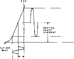 -HEc RESTlNS BIAS VOLTACE URi D IN PUT SIGNAL The simple Class A modulator is limited to an efficiency of about 30%, and the tube must dissipate the full power input during periods of quiescence. Class ЛВ and class В audio systems have largely taken the place of the old Heising modulator because of this great Figure 26 CHARACTERISTIC GRID VOLTAGE-PLATE CURRENT CURVE FOR CLASS A HEISING MODULATOR -e&- CUT-OFF BIAS BIAS-SHIFT EXCURSION CLASS С AMPLIFIER PLATE CURH ENT EXCURSION I P iM/tX S/CIVAL) I P (NO SISNAL ) + Es CLASS A OPEHATI N4 BIAS LINE QUI ESCEMT BIAS LINE Figure 27 BIAS-SHIFT MODULATOR OPERATING CHARACTERISTICS Modulator is biased close to plate current cut-off under no signal, condition, B. Upon application of audio signal, the bias of the stage is shifted toward the class A operating point, A. Bias-shift voltage is obtained from audio signal. and plate dissipation are therefore quite low. Upon application of an audio signal, the bias of the stage is shifted toward the class A operating [xjint, preventing the negative peaks of the applied audio voltage from cutting off the plate current of the tube. As the audio voltage increases, the operating bias point is shifted to the right on figure 27 until the class A operating point is reached at maximum excitation. The bias-shift voltage may be obtained directly from the exciting signal by rectification, as shown in figure 28. A simple low pass filter system is used that will pass only the syllabic components of speech. Enough negative bias is applied to the bias-shift modulator to cut the resting plate current to the desired value, and the output of the bias control rectifier is polarized so as to buck the fixed bias voltage. No spurious modulation frequencies are generated, since the modulator operates class A throughout the audio cycle. This form of grid pulsing permits the modulator stage to work with an pverall efficiency of greater than 50%, comparing favorably with the class В modulator. The expensive class В driver and output transformers are not required, since resistance coupling may be used in the input circuit of the bias-shift modulator, and AUDIO AMPLIFIER BIAS-SHIFT RECTI FI ER SyLLABIC F I LTER BIAS-SHIFT MODULATOR BIAS-SHiFT CONTROL TUBE NEGATIVE BIAS SUPPLY Figure 28 BLOCK DIAGRAM OF BIAS-SHIFT MODULATOR a heavy-duty filter choke will serve as an impedance coupler for the modulated stage. Series and Parallel Control Circuits The bias-shift system make take one of several forms. A series control circuit is shown in figure 29- Resting bias is applied to the bias-shift modulator tube through the voltage divider R2/R4. The bias control tube is placed across resistor R2. Quiescent bias for the modulator is set by adjusting R2. As the internal resistance of the bias control tube is varied at a syllabic rate the voltage drop across R2 will vary in unison. The modulator bias, therefore varies at the same rate. Excitation for the bias control tube is obtained from the audio signal through potentiometer Rl which regulates the amplitude of the control signal. The audio signal is rectified by the bias control rectifier, and filtered by network R3-C1 in the grid circuit of the bias control tube. The parallel control system is illustrated in figure 30. Resting bias for the modulator is obtained from the voltage divider R2/R4. Potentiometer R2 adjusts the resting bias level, determining the static plate current of the modulator. Resistor R3 serves as a bias resistor for the control tube, reducing its plate current to a low level. When an audio signal is applied via Rl to the grid of the control tube the internal resistance is lowered, decreasing the shunt resistance across R2. The negative modulator bias is therefore reduced. The bias axis of the modulator is shifted from the cut-off region to a point on the linear portion of the operating curve. The amount of bias-shift is controlled by the setting of potentiometer Rl. Capacitor Cl in conjunction with bias resistor R3 form a syllabic filter for HANDBOOK Heising Modulator 309 $PE ECH AMPLIFIER B-l- TO MODULATED BIAS-SHIFT R-F AMPLIFIER MODULATOR ADJUST 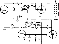 bias CONTROL tube BIAS CONTROL RECTI FI ER NECATIVE MODULATOR BIAS Figure 29 SERIES CONTROL CIRCUIT FOR BIAS-SHIFT MODULATOR The internal resistance of the bias control tube is varied at a syllabic rote to change the operating bias of the modulator tube. SPEECH AMPLIFIER B+ TO MODULATED BIAS-SHIFT H-F AMPLIFIER MODULATOR t >\AOMSTf-l J NEGATIVE R4 MODULATOR - BIAS ADJUST RESTING BIAS ADJUST OPERA TING BIAS -= -1- \BIAS CONTROL Tuee fa- f Figure 30 PARALLEL CONTROL CIRCUIT FOR BIAS-SHIFT MODULATOR Tbe resistance to ground af point A in the bias network is varied at a syllabic rate by the bias control tube. the control bias that is applied to the modulator stage. A large value of plate dissipation is required for the bias-shift modulator tube. For plate voltages below 1500, the 211<VT-4C) may be used, while the 304-TL is suitable for voltages up to 3000. As with normal class A amplifiers, low mu tubes function best in this circuit. A High-Level Bios-Shift Shown in figure 31 is Modulator a bias-shift modulator employing two 304-TL tubes in parallel, operating from a 2500 volt plate supply. This modulator is capable of modulating 1000 watts input to an r-f amplifier. Modulator resting current is adjusted to about 40 milliamperes, rising to about 350 milliamperes on voice peaks . Plate power requirements are approximately the same as a conventional class В modulator. The class С r-f amplifier is adjusted to draw 400 milliamperes at 2500 volts. Two stages of resistance coupled speech amplification are employed, permitting the use of a high gain crystal microphone. The 6J5 stage is transformer coupled to the parallel connected 304-TL tubes. Audio voltage to drive the control tubes is taken from the secondary of the 6J5 coupling transformer. A dual 6SN7 triode is employed as the control rectifier and the control tube. A negative bias supply of approximately -430 volts is required to reduce the plate current of the 304-TL tubes to the proper value. The actual bias at the grid of the 304-TLs is -280 volts. A separate filament supply is required for the 6SN7 control tube in order to remain within themanufacturers recommended heater-cathode breakdown voltage. The filament of this tube is therefore connected to the bias line, rather than being grounded as are the filaments of the other 6-3 volt tubes. The resting bias potentiometer is adjusted for the proper quiescent bias of the 304-TL tubes, determined by the static plate current level, and the audio bias control is then advanced until the operating bias of the modulators drops to approximately -210 volts under conditions of 100% modulation. Since the modulator tube and the r-f amplifier tube operate at the same plate voltage, it will not be possible to actually reach 100% modulation, but an average peak level of over 90% may easily be obtained. A high level low-pass audio filter is placed after the modulator stage to reduce the higher harmonic components generated by the single-ended amplifiers. 304-TL 6sj7 CRYSTAL MICROPHONE 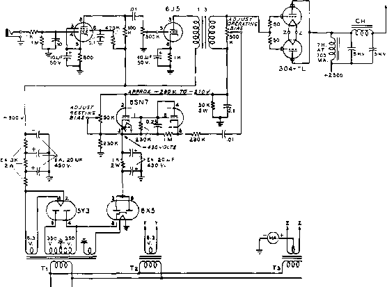 b4- modulated A MPLI F I ER QH-CHICAtO STANOAPD SR-)CO if К LOAD) 7 \ - CMICASO $TANOA/}0 Pc-eioi Тг~СМ/СА 0 ВТАЫОАЯО Р-1в 1 Т* -s volts at 40 amps. NOre - CONNtCr ОЫЕ filament pin op tSN7 CDNTPOL TUBi TO cATHoee {pin i). 0-590 Figure 31 500-WATT BIAS SHIFT MODULATOR Two 304-TL triode tubes in bias controlled class A modulator will effectively modulate one kilowatt input to the class С amplifier stage. Modulator tubes are operated at 2500 volts, and approximately -280 volts bias. Resting bias is adjusted for static plate current of 40 milliamperes. 1 ... 27 28 29 30 31 32 33 ... 80 |
||||||||||
|
© 2026 AutoElektrix.ru
Частичное копирование материалов разрешено при условии активной ссылки |