 |
 |
 |
| Главная Журналы Популярное Audi - почему их так назвали? Как появилась марка Bmw? Откуда появился Lexus? Достижения и устремления Mercedes-Benz Первые модели Chevrolet Электромобиль Nissan Leaf |
Главная » Журналы » Simple coaxial reflectometer 1 ... 28 29 30 31 32 33 34 ... 80
Frequency Modulation and Radioteletype Transmission Exciter systems for FM and single sideband transmission are basically similar in that modification of the signal in accordance with the intelligence to be transmitted is normally accomplished at a relatively low level. Then the intelligence-bearing signal is amplified to the desired power level for ultimate transmission. True, amplifiers for the two types of signals are basically different; linear amplifiers of the Class, A or Class В type being used for ssb signals, while Class С or non-linear Class В amplifiers may be used for FM amplification. But the principle of low-level generation and subsequent amplification is standard for both types of transmission. 16-1 Frequency Modulafion The use of frequency modulation and the allied system of phase modulation has become of increasing importance in recent years. For amateur communication frequency and phase modulation offer important advantages in the reduction of broadcast and TV interference and in the elimination of the costly high-level modulation equipment most commonly employed with amplitude modulation. For broadcast work FM offers an improvement in signal-to-noise ratio for the high field intensities available in the local-coverage area of FM and TV broadcast stations. In this chapter various points of difference between FM and amplitude modulation transmission and reception will be discussed and the advantages of FM for certain types of communication pointed out. Since the distinguishing features of the two types of transmission lie entirely in the modulating circuits at the transmitter and in the detector and limiter circuits in the receiver, these parts of the communication system will receive the major portion of attention. Modulation Modulation is the process of altering a radio wave in accordance with the intelligence to be transmitted. The nature of the intelligence is of little importance as far as the process of modulation is concerned; it is the method by which this intelligence is made to give a distinguishing characteristic to the radio wave which will enable the receiver to convert it back into intelligence that determines the type of modulation being used. Figure 1 is a drawing of an r-f carrier amplitude modulated by a sine-wave audio voltage. After modulation the resultant modulated r-f wave is seen still to vary about the zero axis at a constant rate, but the strength of the individual r-f cycles is proportional to the amplitude of the modulation voltage. In figure 2, the carrier of figure 1 is shown frequency modulated by the same modulating voltage. Here it may be seen that modulation voltage of one polarity causes the carrier frequency to decrease, as shown by the fact that the individual r-f cycles of the carrier are spaced farther art. A modulating voltage of the opposite polarity causes the frequency to Frequency Modulation 313 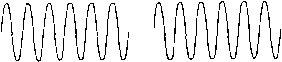 UN MODU LATED C AR WERA MPLITUpE 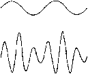 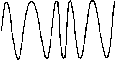 AM AND FM WAVES Figure 1 shows a sketch of the scope patterrt of an anplitude modulated wove at the bottom. The center sketch shows the modulatirtg wove and the upper sketch shows the carrier wave. Figure 2 shows at the bottom a sketch of a frequency modulated wave. In this cose the center sketch also shows the modulatirig wave ond the upper sketch shows the carrier wave. Note that the carrier wove and the modulatirtg wave are the same in either case, but that the waveform of the modulated wave is quite different in the two coses. increase, and tliis is shown by the r-f cycles being squeezed together to allow more of them to be completed in a given time interval. Figures 1 and 2 reveal two very important characteristics about amplitude- and frequency-modulated waves. First, it is seen that while the amplitude (power) of the signal is varied in AM transmission, no such variation takes place in FM. In many cases this advantage of FM is probably of equal or greater importance than the widely publicized noise reduction capabilities of the system. When 100 per cent amplitude modulation is obtained, the average power output of the transmitter must be increased by 50 per cent. This additional output must be supplied either by the modulator itself, in the high-level system, or by operating one or more of the transmitter stages at such a low output level that they are capable of producing the additional output without distortion, in the low-level system. On the other hand, a frequency-modulated transmitter requires an insignificant amount of power from the modulator and needs no provision for increased power output on modulation peaks. All of the stages between the oscillator and the antenna may be operated as high-efficiency Class В or Class С amplifiers or frequency multipliers. SIDE FREQUENCY CARRIER SIDE FREOUENCY FREQUENCY Figure 3 AM SIDE FREQUENCIES For each AM modulating frequency, a pair of side frequencies is produced. The side frequencies are spaced away from the carrier by an amount equal to the modulation frequency, and their amplitude Is directly proportional ta the anplitude of the modulation. The amplitude of the carrier does not chonge under modulation. Carrier-Wave The second characteristic of FM Distortion and AM waves revealed by figures 1 and 2 is that both types of modulation result in distortion of the r-f carrier. That is, after modulation, the r-f cycles are no longer sine waves, as they would be if no frequencies other than the fundamental carrier frequency were present. It may be shown in the amplitude modulation case illustrated, that there are only two additional frequencies present, and these are the familiar side frequencies, one located on each side of the carrier, and each spaced from the carrier by a frequency interval equal to the modulation frequency. In regard to frequency and amplitude, the situation is as shown in figure 3. The strength of the carrier itself does not vary during modulation, but the strength of the side frequencies depends upon the percentage of modulation. At 100 per cent modulation the power in the side frequencies is equal to half that of the carrier. Under frequency modulation, the carrier wave again becomes distorted, as shown in figure 2. But, in this case, many more than two additional frequencies are formed. The first two of these frequencies are spaced from the carrier by the modulation frequency, and the additional side frequencies are located out on each side of the carrier and are also spaced from each other by an amount equal to the modulation frequency. Theoretically, there are an infinite number of side frequencies formed, but, fortunately, the strength of those beyond the frequency siving of the transmitter under modulation is relatively low. One set of side frequencies that might be formed by frequency modulation is shown in figure 4. Unlike amplitude modulation, the UNMODULATED CAR F l£R AMPUTJJDe SIDE FREQUENCIES -.-л- SIDE FREQUENCIES FREQUENCY Figure 4 FM SIDE FREQUENCIES With FM each modulation frequency co/rponenf causes a large number of side frequencies to be produced. The side frequencies are separated from each other and the carrier by an amount equal to the madulation frequency, but their amplitude varies greatly as the amount of modulation Is changed. The carrier strength also varies greatly with frequency modulation. The side frequencies shown represent a case where the deviation each side of the carrier freguency Is equal to five times the modulatirtg frequency. Otfrer amounts of deviation with the same modulation frequency would cause the relative strengths of the various sidebands io chonge widely. Strength of the component at the carrier frequency varies widely in FM and it may even disappear entirely under certain conditions. The variation of strength of the carrier component is useful in measuring the amount of frequency modulation, and will be discussed in detail later in this chapter. One of the great advantages of FM over AM is the reduction in noise at the receiver which the system allows. If the receiver is made responsive only to changes in frequency, a considerable increase in signal-to-noise ratio is made possible through the use of FM, when the signal is of greater strength than the noise. The noise reducing capabilities of FM arise from the inability of noise to cause appreciable frequency modulation of the noise-plus-signal voltage which is applied to the detector in the receiver. FM Terms Unlike amplitude modulation, the term percentage modulation means little in FM practice, unless the receiver characteristics are specified. There are, however, three terms, deviation, modulation index, and deviation ratio, which convey considerable information concerning the character of the FM wave. Deviation is the amount of frequency shift each side of the unmodulated carrier frequency which occurs when the transmitter is modulated. Deviation is ordinarily measured in kilocycles, and in a properly operating FM trans- mitter it will be directly proportional to the amplitude of the modulating signal. When a symmetrical modulating signal is applied to the transmitter, equal deviation each side of the resting frequency is obtained during each cycle of the modulating signal, and the total frequency range covered by the FM transmitter is sometimes known as the stving. If, for instance, a transmitter operating on 1000 kc. has its frequency shifted from 1000 kc. to 1010 kc, back to 1000 kc, then to 990 kc, and again back to 1000 kc. during one cycle of the modulating wave, the deviation would be 10 kc. and the swing 20 kc. The modulation index of an FM signal is the ratio of the deviation to the audio modulating frequency, when both are expressed in the same units. Thus, in the example above if the signal is varied from 1000 kc. to 1010 kc. to 990 kc, and back to 1000 kc. at a rate (frequency) of 2000 times, a second, the mod-idation index would be 5, since the deviation (10 kc.) is 5 times the modulating frequency (2000 cycles, or 2 kc). The relative strengths of the FM carrier and the various side frequencies depend directly upon the modulation index, these relative strengths varying widely as the modulation index is varied. In the preceding example, for instance, side frequencies occur on the high side of 1000 kc at 1002, 1004, 1006, 1008, 1010, 1012, etc., and on the low frequency side at 998, 996, 994, 992, 990, 988, etc. In proportion to the unmodulated carrier strength (100 per cent), these side frequencies have the following strengths, as indicated by a modulation index of 5: 1002 and 998-33 per cent, 1004 and 996-5 per cent, 1006 and 994-36 per cent, 1008 and 992-39 per cent, 1010 and 990-26 per cent, 1012 and 988-13 per cent. The carrier strength (1000 kc.) will be 18 per cent of its unmodulated value. Changing the amplitude of the modulating signal will change the deviation, and thus the modulation index will be changed, with the result that the side frequencies, while still located in the same places, will have different strength values from those given above. The deviation ratio is similar to the modulation index in that it involves the ratio between a modulating frequency and deviation. In this case, however, the deviation in question is the peak frequency shift obtained under full modulation, and the audio frequency to be considered is the maximum audio frequency to be transmitted. When the maximum audio frequency to be transmitted is 5000 cycles, for example, a deviation ratio of 3 would call for a peak deviation of 3 x 5000, or 15 kc. at full modulation. The noise-suppression capabilities of FM are directly related to the deviation ratio. As the deviation ratio is increased. HANDBOOK Narrow Band FM 315 the noise suppression becomes better if the signal is somewhat stronger than the noise. Where the noise approaches the signal in strength, however, low deviation ratios allow communication to be maintained in many cases where high-deviation-ratio FM and conventional AM are incapable of giving service. This assumes that a narrow-band FM receiver is in use. For each value of r-f signal-to-noise ratio at the receiver, there is a maximum deviation ratio which may be used, beyond which the output audio signal-to-noise ratio decreases. Up to this critical deviation ratio, however, the noise suppression becomes progressively better as the deviation ratio is increased. For high-fidelity FM broadcasting рифовез, a deviation ratio of 5 is ordinarily used, the maximum audio frequency being 15,000 cycles, and the peak deviation at full modulation being 75 kc. Since a swing of 150 kc. is covered by the transmitter, it is obvioiifs that wideband FM transmission must necessarily be confined to the v-h-f range or higher, where room for the signals is available. In the case of television sound, the deviation ratio is 1.67; the maximum modulation frequency is 15,000 cycles, and the transmitter deviation for full modulation is 25 kc. The sound carrier frequency in a standard TV signal is located exactly 4.5 Mc. higher than the picture carrier frequency. In the inter-carrier TV sound system, which recently has become quite widely used, this constant difference between the picture carrier and the sound carrier is employed within the receiver to obtain an FM sub-carrier at 4.5 Mc. This 4.5 Mc. sub-carrier then is demodulated by the FM detector to obtain the sound signal which accompanies the picture. Narrow-Band Narrow-band FM trans- FM Transmission mission has become standardized for use by the mobile services such as police, fire, and taxi-cab communication, and also on the basis of a temporary authorization for amateur work in portions of each of the amateur radiotelqihone bands. A maximum deviation of 15 kc. has been standardized for the mobile and commercial communication services, while a maximum deviation of 3 kc. is authorized for amateur NBFM communication. Bandwidth Re- As the above discussion has quired by FM indicated, many side frequencies ate set up when a radio-frequency carrier is frequency modulated; theoretically, in fact, an infinite number of side frequencies is formed. Fortunately, however, the amplitudes of those side frequencies falling outside the frequency range over which the transmitter is swung are so small that пюst of them may be ignored. In FM transmission, when a complex modidating wave (speech or music) is used, still additional side frequencies resulting from a beating together of the various frequency components in the modulating wave are formed. This is a situation that does not occur in amplitude modulation and it might be thought that the large number of side frequencies thus formed might make the frequency spectrum produced by an FM transmitter prohibitively wide. Analysis shows, however, that the additional side frequencies are of very small amplitude, and, instead of increasing the bandwidth, modulation by a complex wave actually reduces the effective bandwidth of the FM wave. This is especially true when speech modulation is used, since most of the power in voiced sounds is concentrated at low frequencies in the vicinity of 400 cycles. The bandwidth required in an FM receiver is a function of a number of factors, both theoretical and practical. Basically, the bandwidth required is a function of the deviation ratio and the maximum frequency of modulation, although the practical consideration of drift and ease of receiver tuning also must be considered. Shown in figure 5 are the frequency spectra (carrier and sideband frequencies) associated with the standard FM broadcast signal, the TV sound signal, and an amateur-band narrow-band FM signal with full modulation using the highest permissible modulating frequency in each case. It will be seen that for low deviation ratios the receiver bandwidth should be at least foiu times the maximum frequency deviation, but for a deviation ratio of 5 the receiver bandwidth need be only about 2.5 times the maximum frequency deviation. 16-2 Direct FM Circuits Frequency modulation may be obtained either by the direct method, in which the frequency of an oscillator is changed directly by the modulating signal, от by the indirect method which makes use of phase modulation. Phase-modulation circtiits will be discussed in section 16-3. A successful frequency modulated transmitter must meet two requirements: (1) The frequency deviation must be symmetrical about a fixed frequency, for symmetrical modulation voltage. (2) The deviation must be directly proportional to the amplitude of the modulation, and independent of the modulation frequency. There are several methods of direct frequency modulation which will fulfill these FM BROADCAST DEVIATION-75 ЛС MOD. FREQ.-и КС. MOO. INDEX - J -105 -90 -75 -60 -45 -30 -1S (?) TV SOUND + 15 +30 +45 +eO +75 +90 +105 DEVIATION-as KC. MOD. FREQ.- 15 KC. MOD. INDEX -1.67 -45 kc- -30 c- -икс. + 15 КС. -I-30 КС. +45 КС. AUDIO IN 6BA6 Сг,47 1 47,01 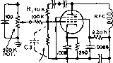 OSCILLATOR IN 1.75 MC. RANGE  .0068 +i5o-aoov. REGULATED Figure 6 REACTANCE-TUBE MODULATOR This circuit is convenient for direct frequency modulation of an oscillatar in the 1.7S-Mc. range. Capacitor C3 may be only the input capacitance of the tube, or a small trimmer capacitor may be included io permit a variation in the sensitivity of the reactance tube. (C) AMATEUR NBFM DEVIATION - 3 KC, MOD. FREQ.- 3 KC. MOD. INDEX - I CENTER FREQUENCY Figure 5 EFFECT OF FM MODULATION INDEX Showing the side-frequency amplitude and distribution for the three most common modulation indices used in FM work. The maximum modulating frequency and maximum deviation are shown In each case. requirements. Some of these methods will be described in the following paragraphs. Reactonce-Tobe One of the most practical Modulators ways of obtaining direct fre- quency modulation is through the use of a reactance-tube modulator. In this arrangement the modulator plate-cathode circuit is connected across the oscillator tank circuit, and made to appear as either a capacitive or inductive reacrance by exciting the modulator grid with a voltage which either leads or lags the oscillator tank voltage by 90 degrees. The leading or lagging grid voltage causes a corresponding leading or lagging plate current, and the plate-cathode circuit appears as a capacitive or inductive reactance across the oscillator tank circuit. When the transconductance of the modulator tube is varied, by varying one of the element voltages, the magnitude of the reactance across the os- cillator tank is varied. By applying audio modulating voltage to one of the elements, the transconductance, and hence the frequency, may be varied at an audio rate. When properly designed and operated, the reactance-tube modulator gives linear frequency modulation, and is capable of producing large amounts of deviation. There are numerous possible configurations of the reactance-tube modulator circuit. The difference in the various arrangements lies principally in the type of phase-shifting circuit used to give a grid voltage which is in phase quadrature with the r-f voltage at the modulator plate. Figure 6 is a diagram of one of the most popular forms of reactance-tube modulators. The modulator tube, which is usually a pentode such as a 6BA6, 6AU6, or 6CL6, has its plate coupled through a blocking capacitor, Cl, to the hot side of the oscillator grid circuit. Another blocking capacitor, C feeds r.f. to the phase shifting network R-C3 in rhe modulator grid circuit. If the resistance of R is made large in comparison with the reactance of C3 at the oscillator frequency, the current through the R-C3 combination will be nearly in phase with the voltage across the tank circuit, and the voltage across C3 will lag the oscillator tank voltage by almost 90 degrees. The result of the 90-degree lagging voltage on the modulator grid is that its plate current lags the tank voltage by 90 degrees, and the reactance tube appears as an inductance in shunt with the oscillator inductance, thus raising the oscillator frequency. The phase-shifting capacitor Cj can consist of the input capacitance of the modulator tube and stray capacitance between grid and ground. HANDBOOK Reactance Tube 317 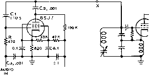 + (50-250 v. regulated Figure 7 ALTERNATIVE REACTANCE-TUBE MODULATOR This circuit is often preferable for use in the lower frequency range, although it may be used at 7.75 Mc. and above if desired. In the schematic above tbe reactance tube is shown connected across the voltage-divider capacitors of a Clapp oscillator, although the modulator circuit may be used with any common type of oscillator. However, better control of the operating conditions of ttie modulator may be had througti the use of a variable capacitor as C3. Resistance R will usually have a value of between 4700 and 100,000 ohms. Either resistance or transformer coupling may be used to feed audio voltage to the modulator grid. When a resistance coupling is used, it is necessary to shield the grid circuit adequately, since the high impedance grid circuit is prone to pick up stray r-f and low frequency a-c voltage, and cause undesired frequency modulation. An alternative reactance modulator circuit is shown in figure 7. The operating conditions are generally the same, except that the r-f excitation voltage to the grid of the reactance tube is obtained effectively through reversing the R and Cj of figure 6. In this circuit a small capacitance is used to couple r.f. into the grid of the reactance tube, with a relatively small value of resistance from grid to ground. This circuit has the advantage that the grid of the tube is at relatively low impedance with respect to r.f. However, the circuit normally is not suitable for operation above a few megacycles due to the shunting capacitance within the tube from grid to ground. Either of the reactance-tube circuits may be used with any of the common types of oscillators. The reactance modulator of figvire 6 is shown connected to the high-impedance point of a conventional hot-cathode Hartley oscillator, while that of figure 7 is shown connected across the low-impedance capacitors of a series-tuned Clapp oscillator. There are several possible variations of the basic reactance-tube modulator circuits shown in figures 6 and 7. The audio input may be applied to the suppressor grid, rather than the control grid, if desired. Another modification is to apply the audio to a grid other than the control grid in a mixer or pentagrid converter tube which is used as the modulator. Generally, it will be found that the transconductance variation per volt of control-element voltage variation will be greatest when the control (audio) voltage is applied to the control grid. In cases where it is desirable to separate completely the audio and r-f circuits, however, applying audio voltage to one of the other elements will often be found advantageous despite the somewhat lower sensitivity. Ad[usting the One of the simplest methods Phase Shift of adjusting the phase shift to the correct amount is to place a pair of eaфhones in series with the oscillator cathode-to-ground circuit and adjust the phase-shift network until minimum sound is heard in the phones when frequency modulation is taking place. If an electron-coupled or Hartley oscillator is used, this method requires that the cathode circuit of the oscillator be inductively or capacitively coupled to the grid circuit, rather than tapped on the grid coil. The phones should be adequately bypassed for r.f. of course. Stabilization Due to the presence of the reactance-tube frequency modulator, the stabilization of an FM oscillator in regard to voltage changes is considerably more involved than in the case of a simple self-controlled oscillator for transmirter frequency control. If desired, the oscillator itself may be made perfectly stable under voltage changes, but the presence of the frequency modulator destroys the beneficial effect of any such stabilization. It thus becomes desirable to ply the stabilizing arrangement to the modulator as well as the oscillator. If the oscillator itself is stable under voltage changes, it is only necessary to apply voltage-frequency compensation to the modulator. Reactance-Tube Two simple reactance-tube Modulators modulators that maybe applied to an existing v.f.o. are illustrated in figures 8 and 9. The circuit of figure 8 is extremely simple, yet effective. Only two tubes are used exclusive of the voltage regulator tubes which perhaps may be already incorporated in the v.f.o. A 6AU6 serves as a high-gain voltage amplifier stage, and a 6CL6 is used as the reactance modulator since its higfi value of transconductance will permit a large value of lagging current to be drawn under modulation swing. The unit should be Qv-VW 6AU6  6CLe I.2U °7-а.,кфо, it VR150 VRI50 470 L .. i, fiOO JUJUF -► TO GRID OH CATHODE OF V.F.O. 47 K, RFC NOTE-. ALL neSISTORS O.S WATT UNLESS г. S m H о TH£R WISE NOTED ALL CAPACITORS IN MP UNLESS ш OTHERWISE NOTED ADJUST FOR CORRECT VR CURRENT Figure 8 SIMPLE FM REACTANCE-TUBE MODULATOR mounted in close proximity to the v.f.o. so that the lead from the 6CL6 to the grid circuit of the oscillator can be as short as possible. A practical solution is to mount the reactance modulator in a small box on the side of the v-f-o cabinet. By incorporating speech clipping in the reactance modulator unit, a much more effective use is made of a given amount of deviation. When the FM signal is received on an AM receiver by means of slope detection, the use of speech clipping will be noticed by the greatly increased modulation level of the FM signal, and the attenuation of the center frequency null of no modulation. In many cases, it is difficult to tell a speech-dipped FM signal from the usual AM signal. A more complex FM reactance modulator incorporating a speech clipper is shown in figure 9. A 12AX7 double triode speech amplifier provides enough gain for proper clipper action when a high level crystal microphone is used. A double diode 6AL5 speech clipper is used, the clipping level being set by the potentiometer controlling the plate voltage applied to the diode. A 6CL6 serves as the reactance modulator. The reactance modulator may best be adjusted by listening to the signal of the v-f-o exciter at the operating frequency and adjusting the gain and clipping controls for the best modulation level consistent with minimum sideband splatter. Minimum clipping occurs when the Adj. Clip, potentiometer is set for majcimuro voltage on the plates of the 6AL5 clipper tube. As with the case of all reactance modulators, a voltage regulated plate supply is required. Linearity Test It is almost a necessity to run a static test on the reactance-tube frequency modulator to determine its linearity and effectiveness, since small changes in the values of components, and in stray capacitances will almost certainly alter the modulator characteristics. A frequency-versus-con-trol-voltage curve should be plotted to ascertain that equal increments in control voltage, both in a positive and a negative direction, cause equal changes in frequency. If the curve shows that the modulator has an appreciable amount of non-linearity, changes in bias, electrode voltages, r-f excitation, and resistance n. 4 SOOUJUF 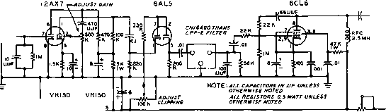 TO GRID OR CATHODE OF V.F.O. ADJUST FOR CORRECT VR CURRENT Figure 9 FM REACTANCE MODULATOR WITH SPEECH CLIPPER to modulator control element © -wl/w - + - iiliHr4iiH Figure 10 REACTANCE-TUBE LINEARITY CHECKER values may be made to obtain a straight-line characteristic. Figure 10 shows a method of connecting two 42-volt С batteries and a potentiometer to plot the characteristic of the modulator. It will be necessary to use a zero-center voltmeter to measure the grid voltage, or else reverse the voltmeter leads when changing from positive to negative grid voltage. When a straight-line characteristic for the modulator is obtained by the static test method, the capacitances of the various by-pass capacitors in the circuit must be kept small to retain this characteristic when an audio voltage is used to vary the frequency in place of the d-c voltage with which the characteristic was plotted. 16-3 Phase Modulation By means of phase modulation (PM) it is possible to dispense with self-controlled oscillators and to obtain directly crystal-controlled FM. In the final analysis, PM is simply frequency modulation in which the deviation is directly proportional to the modulation frequency. If an audio signal of 1000 cycles causes a deviation of Уг kc, for example, a 2000-cycle modulating signal of the same amplitude will give a deviation of 1 kc, and so on. To produce an FM signal, it is necessary to make the deviation independent of the modulation frequency, and proportional only to the modulating signal. With PM this is done by including a frequency correcting network in the transmitter. The audio correction network must have an attenuation that varies directly with frequency, and this requirement is easily met by a very simple resistance-capacity network. The only disadvantage of PM, as compared to direct FM such as is obtained through the use of a reactance-tube modulator, is the fact that very little frequency deviation is produced directly by the phase modulator. The deviation produced by a phase modulator is independent of the actual carrier frequency on which the modulator operates, but is dependent only upon the phase deviation which is being produced and upon the modulation frequency. Expressed as an equation: Mp modulating frequency Where Fj is the frequency deviation one way from the mean value of the carrier, and Mp is the phase deviation accompanying modulation expressed in radians (a radian is approximately 57.3°). Thus, to take an example, if the phase deviation is Уг radian and the modulating frequency is 1000 cycles, the frequency deviation applied to the carrier being passed through the phase modulator will be 500 cycles. It is easy to see that an enormous amount of multiplication of the carrier frequency is required in order to obtain from a phase modulator the frequency deviation of 75 kc. required for commercial FM broadcasting. However, for amateur and commercial narrow-band FM work (NBFM) only a quite reasonable number of multiplier stages are required to obtain a deviation ratio of approximately one. Actually, phase modulation of approximately one-half radian on the ouфut of a crystal oscillator in the 80-meter band will give adequate deviation for 29-Mc NBFM radiotelephony. For example; if the crystal frequency is 3700 kc, the deviation in phase produced is Уг radian, and the modulating frequency is 500 cycles, the deviation in the 80-meter band will be 250 cycles. But when the crystal frequency is multiplied on up to 29,600 kc. the frequency deviation will also be multiplied by 8 so that the resulting deviation on the 10-meter band will be 2 kc. either side of the carrier for a total swing in carrier frequency of 4 kc. This amount of deviation is quite adequate for NBFM work. Odd-harmonic distortion is produced when FM is obtained by the phase-modulation method, and the amount of this distortion that can be tolerated is the limiting factor in determining the amount of PM that can be used. Since the aforementioned frequency-correcting network causes the lowest modulating frequency to have the greatest amplitude, maximum phase modulation takes place at the lowest modulating frequency, and the amount of distortion that can be tolerated at this frequency determines the maximum deviation that can be obtained by the PM method. For high-fidelity broadcasting, the deviation produced by PM is limited to an amount equal to about one-third of the lowest modulating frequency. But for NBFM work the deviation may be as high as 0.6 of the modulating frequency before distortion becomes objectionable on voice modulation. In Other terms this means that phase deviations as high as 0.6 radian may be used for amateur and commercial NBFM transmission. REACTANCE TUBE CRYSTAL OSCILLATOR TUBE taYe 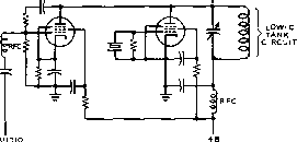 Figure 11 REACTANCE-TUBE MODULATION OF CRYSTAL OSCILLATOR STAGE Phose-Modulation A simple reactance modula-Circuits tor normally used for FM may also be used for PM by connecting it to the plate circuit of a crystal oscillator stage as shown in figure 11. Another PM circuit, suitable for operation on 20, 15 and 10 meters with the use of 80 meter crystals is shown in figure 12. A double triode 12AX7 is used as a combination Pierce crystal oscillator and phase modulator. C, should not be thought of as a neutralizing condenser, but rather as an adjustment for the phase of the r-f voltage acting between the grid and plate of the 12AX7 phase modulator. Cj acts as a phase angle and magnitude control, and both these condensers should be adjusted for maximum phase modulation capabilities of the circuit. Resonance of the circuit is established by the iron slug of coil Li-Lj. A 6CL6 is used as a doubler to 7 Mc. and delivers proximately 2 watts on this band. Additional doublet stages may be added after the 6CL6 stage to reach the desired band of operation. Still another PM circuit, which is quite widely used commercially, is shown in figure 13. In this circuit L and С are made resonant at a frequency which is 0.707 times the operating frequency. Hence at the operating frequency the inductive reactance is twice the capacitive reactance. A cathode follower tube acts as a variable resistance in series with the L and С which go to make up the tank circuit. The operating point of the cathode follower should be chosen so that the effective resistance in series with the tank circuit (made up of the resistance of the cathode-follower tube in parallel with the cathode bias resistor of the cathode follower) is equal to the capacitive reactance of the tank capacitor at the operating frequency. The circuit is capable of about plus or minus Уг radian deviation with tolerable distortion. Measurement When a single-frequency mod- of Deviotion ulating voltage is used with an FM transmitter, the relative amplitudes of the various sidebands and the carrier vary widely as the deviation is varied by increasing or decreasing the amount of modulation. Since the relationship between the amplitudes of the various sidebands and carrier to the audio modulating frequency and the deviation is known, a simple method of measuring the deviation of a frequency modulated transmitter is possible. In making the measurement, the result is given in the form of the modulation index for a certain amount of audio input. As previously described, the modulation index is the ratio of the peak frequency deviation to the. frequency of the audio modulation. The measurement is made by applying a sine-wave audio voltage of known frequency to the transmitter, and increasing the modulation until the amplitude of the carrier component of the frequency modulated wave reaches zero. The modulation index for zero carrier may then be determined from the table below. As may be seen from the table, the first point of zero carrier is obtained when the modulation index has a value of 2.405,-in other words, when the deviation is 2.405 times the modulation frequency. For example, if a modulation frequency of 1000 cycles is used, and the modulation is increased until the first carrier null is obtained, the deviation will then be 2.405 times the modulation frequency, or 2.405 kc. If the modulating frequency happened to be 2000 cycles, the deviation at the first null would be 4.810 kc. Other carrier nulls will be obtained when the index is 5-52, 8.654, and at increasing values separated approximately by n. The following is a listing of the modulation index at successive carrier nulls up to the tenth: Zero carrier point no. 1 2 3 4 5 6 7 8 9 10 Modulation index 2.405 5.520 8.654 11.792 14.931 18.071 21.212 24.353 27.494 30.635 The only equipment required for making the measurements is a calibrated audio oscillator of good wave form, and a communication receiver equipped with a beat oscillator and crystal filter. The receiver should be used with its crystal filter set for minimum bandwidth to exclude sidebands spaced from the carrier by the modulation frequency. The un- 1 ... 28 29 30 31 32 33 34 ... 80 |
||||||||||||||||||||||||||||||||||||||||||||||||||||||||||||||||||||||||||||||||||||||||||||||||||||||||||||||||||||||||||||||||||||||||||||||||||||||||||||||||||||||||||||||||||||||||||||||||||||||||||||||||||||||||
|
© 2026 AutoElektrix.ru
Частичное копирование материалов разрешено при условии активной ссылки |