 |
 |
 |
| Главная Журналы Популярное Audi - почему их так назвали? Как появилась марка Bmw? Откуда появился Lexus? Достижения и устремления Mercedes-Benz Первые модели Chevrolet Электромобиль Nissan Leaf |
Главная » Журналы » Simple coaxial reflectometer 1 ... 29 30 31 32 33 34 35 ... 80 I2AX7 6CL6 s.SMc: J XTAL- RFC Z 2-5 MhS XTAL mx 4,7 к П\/-iW- 10 jujuf 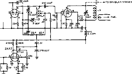 Li-36Г. #36f.\ swfo 4 apart onform LilS t. язве.! powoereo iron core 300 v, L3-37T. ttZOE. CLOSE-SPACED f DIA. NOTE; ALL RESISTORS O.SWATT UNLESS OTHERWISE NOTED. ALL CAPACITORS IN iJP UNLESS OTHERWISE NOTED Figure 12 REACTANCE MODULATOR FOR 10, 15 AND 20 METER OPERATION modulated carrier is accurately tuned in on the receiver with the beat oscillator operating. Then modulation from the audio oscillator is applied to the transmitter, and the modulation is increased until the first carrier null is obtained. This carrier null will correspond to a modulation index of 2.405, as previously mentioned. Successive null points will correspond to the indices listed in the table. A volume indicator in the transmitter audio system may be used to measure the audio level required for different amounts of deviation, and the indicator thus calibrated in terms of frequency deviation. If the measurements are made at the fundamental frequency of the oscillator, it will be necessary to multiply the frequency deviation by the harmonic upon which the transmitter is operating, of course. It will probably be most convenient to make the determination at some frequency intermediate between that of the oscillator and that at which the transmitter is operating, and then to multiply the result by the frequency multiplication between that frequency and the transmitter output frequency. 16-4 Reception of FM Signals as used by FM broadcast stations, TV sound, and mobile communications FM. The FM receiver must have, first of all, a bandwidth sufficient to pass the range of frequencies generated by the FM transmitter. And since the receiver must be a superheterodyne if it is to have good sensitivity at the frequencies to which FM is restricted, i-f bandwidth is an important factor in its design. The second requirement of the FM receiver is that it incorporate some sort of device for converting frequency changes into amplitude changes, in other words, a detector operating on frequency variations rather than amplitude variations. The third requirement, and one which is necessary if the full noise reducing capa- 6SJ7 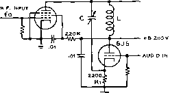 phase-mooulated output Xl about 1500 n at fo Xc about 75011. at fo A conventional communications receiver may be used to receive narrow-band FM transmissions, although performance will be much poorer than can be obtained with an NBFM receiver or adapter. However, a receiver specifically designed for FM reception must be used when it is desired to receive high deviation FM such Figure 13 CATHODE-FOLLOWER PHASE MODULATOR Tbe phase modulator illustratBd above Is quite satisfactory when fhe stage is to be operated on о single frequency or over о nor-ГОМГ range of frequencies. MIXER - I.F. AMPLIFIER - LIMITER - CDISCRIMINAfbR) AUDIO AMP. OSCILLATOR Figure 14 FM RECEIVER BLOCK DIAGRAM Up to the amplitude limiter stage, the FM receiver is similar to an AM receiver, except for a somewhat wider i-f bandwidth. The limiter removes any amplitude modulation, and the frequency detector following the limiter converts frequency variations info amplitude variations. 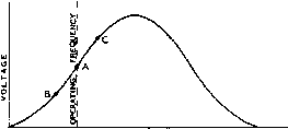 FREQUENCY Figure 15 SLOPE DETECTION OF FM SIGNAL One side of the response characteristic of a funed circuit or of an i-f amplifier may be used as shown to convert frequency variations of an incoming signal into amplitude variations. bilities of the FM system of transmission are desired, is a limiting device to eliminate amplitude variations before they reach the detector. A block diagram of the essential parts of an FM receiver is shown in figure 14, The Frequency The simplest device for con-Detector verting frequency variations ro amplitude variations is an off-tune resonant circuit, as illustrated in figure 15. Wirh the carrier tuned in at point A, a certain amount of r-f voltage will be developed across the tuned circuit, and, as the frequency is varied either side of this frequency by the modulation, the r-f voltage will increase and decrease to points C and B in accordance with the modulation. If the voltage across the tuned circuit is applied to an ordinary detector, the detector оифиг will vary in accordance with the modulation, the amplitude of the variation being proportional to the deviation of the signal, and the rate being equal to the modulation frequency. It is obvious from figure 15 that only a small portion of the resonance curve is usable for linear conversion FROM I.F. AMP. 7Г о AUDIO R) OUTPUT Figure 16 TRAVIS DISCRIMINATOR This type of discriminator makes use of two off-tuned resonant circuits coupled to a single primary winding. The circuit is capable of excellent linearity, but Is difficult to a-llgn. of frequency variarions into amplitude variations, since the linear portion of rhe curve is rather short. Any frequency variation which exceeds the linear portion will cause distortion of the recovered audio. It is also obvious by inspection of figure 15 that an AM receiver used in this manner is wide open to signals on the peak of the resonance curve and also to signals on the other side of the resonance curve. Further, no noise limiting action is afforded by this type of reception. This system, therefore, is not recommended for FM reception, although widely used by amateurs for occasional NBFM reception. Trovis Discriminator Another form of frequency detector or discriminator, is shown in figure 16. In this arrangement two tuned circuits are used, one runed on each side of the i-f amplifier frequency, and with their resonant frequencies spaced slightly more than the expected Transmitter swing. Their outputs are combined in a differential rectifier so that the voltage across the series load resistors, Ri and R, is equal ro the algebraic sum of the individual output voltages of each rectifier. When a signal at the At Its center fre-quency the discriminator produces zero i output V ol t ag e. On either side of this i frequency It gives J a voltage of a polar- ity and magnitude \ which depend on the direction and amount of frequency shift. Figure 17 DISCRIMINATOR VOLTAGE-FREQUENCY CURVE FREQUENCY LIMITER о о 7Г § о о о о о AUDIO OUTPUT Figure 18 FOSTER-SEELEY DISCRIMINATOR This discriminator is the most widely used circuit since it is capable of excellent lin-earity and is relatively simple to align when proper test equipment is available. i-f mid-frequency is received, the voltages across the load resistors are equal and opposite, and the sum voltage is zero. As the r-f signal varies from the mid-frequency, however, these individual voltages become unequal, and a voltage having the polarity of the larger voltage and equal to the difference between the two voltages appears across the series resistors, and is applied to the audio amplifier. The relationship between frequency and discriminator output voltage is shown in figure 17. The separation of the discriminator peaks and the linearity of the output voltage vs. frequency curve depend upon the discriminator frequency, the Q of the tuned circuits, and the value of the diode load resistors. As the intermediate (and discriminator) frequency is increased, the peaks must be separated further to secure good linearity and output. Within limits, as the diode load resistance or the Q is reduced, the linearity improves, and the separation between the peaks must be greater. Foster-Seeley The most widely used form of Discriminator discriminator is that shown in figure 18. This type of discriminator yields an output-voltage-versus-frequen-cy characteristic similar to that shown in figure 19- Here, again, the ouфut voltage is equal to the algebraic sum of the voltages developed across the load resistors of the two diodes, the resistors being connected in series to ground. However, this Foster-Seeley discriminator requires only two tuned circuits instead of the three used in the previous discriminator. The operation of the circuit results from the phase relationships existing in a transformer having a tuned secondary. In effect, as a close examination of the circuit will reveal, the primary circuit is in series, for r.f with each half of the secondary to ground. When the received signal is at the resonant frequency of the secondary, the r-f voltage across the secondary is 90 degrees out of phase with that across the primary. Since each diode is connected across one half of the secondary wind- 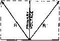 SECONDARY VOLTAGE 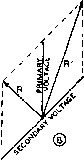 Figure 19 DISCRIMINATOR VECTOR DIAGRAM A signal at the resonant frequency of the secondary will cause the secondary voltage to be 90 degrees out of phase with the primary voltage, as shown ot A, and the resultant voltages R and R are equal. If the signal frequency changes, the phase relationship also changes, and the resultant voltages are no longer equal, as shown at B. A differential rectifier is used to give an output voltage proportional to the difference between R and R. ing and the primary winding in series, the resultant r-f voltages applied to each are equal, and the voltages developed across each diode load resistor are equal and of opposite polarity. Hence, the net voltage between the top of the load resistors and ground is zero. This is shown vectorially in figure 19A where the resultant voltages R and R which are applied to the two diodes are shown to be equal when the phase angle between primary and secondary voltages is 90 degrees. If, however, the signal varies from the resonant frequency, the 90-degree phase relationship no longer exists between primary and secondary. The result of this effect is shown in figure 19B where the secondary r-f voltage is no longer 90 degrees out of phase with respect to the primary voltage. The resultant voltages applied to the two diodes are now no longer equal, and a d-c voltage proportional to the difference between the r-f voltages applied to the two diodes will exist across the series load resistors. As the signal frequency varies back and forth across the resonant frequency of the discriminator, an a-c voltage of the same frequency as the original modulation, and proportional to the deviation, is developed and passed on to the audio amplifier. Rotio One of the more recent types of FM Detector detector circuits, called the ratio detector is diagrammed in figure 20. The input transformer can be designed so that the parallel input voltage to the diodes can be taken from a tap on the primary of the trans- .000) RFC LAST о о о о о о о 6sj7 6Н6 он 6AL5 Г / \ Тоог L ±- A.V.C OUTPUT A.F. OUTPUT Figure 20 RATIO DETECTOR CIRCUIT The parallel voltage to the diodes in a ratio detector may be obtained from a tap on the primary winding of the transformer or from a third winding. Note that one of the diodes is reversed from the system used with the Foster-Seeley discriminator, and thai the output circuit is completely different. The ratio detector does not have to be preceded by a limiter, but is more difficult to align for distortion-free output than the conventional t/iscrim ino/or. former, or this voltage may be obtained from a tertiary winding coupled to the primary. The r-f choke used must have high impedance at the intermediate frequency used in the receiver, although this choke is not needed if the transformer has a tertiary winding. The circuit of the ratio detector appears very similar to that of the more conventional discriminator arrangement. However, it will be noted that the two diodes in the ratio detector are poled so that their d-c output voltages add, as contrasted to the Foster-Seeley circuit wherein the diodes are poled so that the d-c output voltages buck each other. At the center frequency to which the discriminator transformer is tuned the voltage appearing at the top of the 1-megohm potentiometer will be one-half the d-c voltage appearing at the a-v-c output terminal-since the contribution of each diode will be the same. However, as the input frequency varies to one side or the other of the tuned value (while remaining within the pass band of the i-f amplifier feeding the detector) the relative contributions of the two diodes will be different. The voltage appearing at the top of the 1-megohm volume control will increase for frequency deviations in one direction and will decrease for frequency deviations in the other direction from the mean or tuned value of the transformer. The audio output voltage is equal to the ratio of the relative contributions of the two diodes, hence the name ratio detector. The ratio detector offers several advantages over the simple discriminator circuit. The circuit does not require the use of a limiter preceding the detector since the circuit is inherently insensitive to amplitude modidation on Wr- О о CJ - o о JL 7Г DISCRIMINATOR Figure 21 LIMITER CIRCUIT One, or sometimes two, limiter stages normally precede the discriminator so thai a constant signal level will be fed to the FM detector. This procedure eliminates amplitude variations in the signal fed to the discriminator, so that it will respond only to frequency changes. an incoming signal. This factor alone means that the r-f and i-f gain ahead of the detector can be much less than the conventional discriminator for the same overall sensitivity. Further, the circuit provides a-v-c voltage for controlling the gain of the preceding r-f and i-f stages. The ratio detector is, however, susceptible to variations in the amplitude of the incoming signal as is any other detector circuit except the discriminator uiith a limiter preceding it, so that a-v-c should be used on the stages preceding the detector. Limiters The limiter of an FM receiver using a conventional discriminator serves to remove amplitude modulation and pass on to the discriminator a frequency modulated signal of constant amplitude; a typical circuit is shown in figure 21. The limiter tube is operated as an i-f stage with very low plate voltage and with grid leak bias, so that it overloads quite easily. Up to a certain point the output of the limiter will increase with an increase in signal. Above this point, however, the limiter becomes overloaded, and further large increases in signal will not give any increase in output. To operate successfully, the limiter must be supplied with a large amount of signal, so that the amplitude of its ouфut will not change for rather wide variations in amplitude of the signal. Noise, which causes little frequency modulation but much amplitude modulation of the received signal, is virtually wiped out in the limiter. The voltage across the grid resistor varies with the amplitude of the received signal. For this reason, conventional amplitude modulated signals may be received on the FM receiver by connecting the input of the audio amplifier to the top of this resistor, rather than to the discriminator ouфut. When properly filtered HANDBOOK NBFM Adapter 325 by a simple R-C circuit, the voltage across the grid resistor may also be used as a-v-c voltage for the receiver. When the limiter is operating properly, a.v.c. is neither necessary nor desirable, however, for FM reception alone. Receiver Design One of the most important Considerations factors in the design of an FM receiver is the frequency swing which it is intended to handle. It will be apparent from figure 17 that if the straight portion of the discriminator circuit covers a wider range of frequencies than those generated by the transmitter, the audio ouфut will be reduced from the maximum value of which the receiver is capable. In this respect, the term modulation percentage is more applicable to the FM receiver than it is to the transmitter, since the modulation capability of the communication system is limited by the receiver bandwidth and the discriminator characteristic; full utilization of the linear portion of the characteristic amounts, in effect, to 100 per cent modulation. This means that some sort of standard must be agreed upon, for any particular type of communication, to make it unnecessary to vary the transmitter swing to accommodate different receivers. Two considerations influence the receiver bandwidth necessary for any particular type of communication. These are the maximum audio frequency which the system will handle, and the deviation ratio which will be employed. For voice communication, the maximum audio frequency is more or less fixed at 3000 to 4000 cycles. In the matter of deviation ratio, however, the amount of noise suppression which the FM system will provide is influenced by the ratio chosen, since the improvement in signal-to-noise ratio which the FM system shows over amplitude modulation is equivalent to a constant multiplied by the deviation ratio. This assumes that the signal is somewhat stronger than the noise at the receiver, however, as the advantages of wideband FM in regard to noise suppression disappear when the signal-to-noise ratio approaches unity. On the other hand, a low deviation ratio is more satisfactory for strictly communication work, where readability at low signal-to-noise ratios is more important than additional noise suppression when the signal is already appreciably stronger than the noise. As mentioned previously, broadcast FM practice is to use a deviation ratio of 5. When this ratio is applied to a voice-communication system, the total swing becomes 30 to 40 kc. With lower deviation ratios, such as are most frequently used for voice work, the swing becomes proportionally less, until at a deviation ratio of 1 the swing is equal to twice the highest audio frequency. Actually, however, the re- FROM DISCRIMINATOR -Wr- TO AUDIO GRID R= 220l\, C= 340JJJJF. R= 100 ft, C= 750 XllIF, R = 47 K, С = 1600 IIUF. R= гг K, C= 3400 jUijF, Figure 22 75-MICROSECOND DE-EMPHASIS CIRCUITS The audio signal transmitted by FM and TV stations has received high-frequency pre-emphasis, so that a de-emphasis circuit should be included between the output of the FM detector and the input of t h e audio system. ceiver bandwidth must be slightly greater than the expected transmitter swing, since for distortionless reception the receiver must pass the complete band of energy generated by the transmitter, and this band will always cover a range somewhat wider than the transmitter swing. Pre-Emphosis Standards in FM broadcast ond De-Emphasis and TV sound work call for the pre-emphasis of all audio modulating frequencies above about 2000 cycles, with a rising slope such as would be produced by a 75-microsecond RL network. Thus the FM receiver should include a compensating de-emphasis RC network with a time constant of 75 microseconds so that the overall frequency response from microphone to loudspeaker will approach linearity. The use of pre-emphasis and de-emphasis in this manner results in a considerable improvement in the overall signal-to-noise ratio of an FM system. Appropriate values for the de-emphasis network, for different values of circuit impedance are given in figure 22. A NBFM 455-Icc. The unit diagrammed in figure Adapter Unit 23 is designed to provide NBFM reception when attached to any communication receiver having a 455-kc. i-f amplifier. Although NBFM can be received on an AM receiver by tuning the receiver to one side or the other of the incoming signal, a tremendous improvement in signal-to-noise ratio and in signal to amplitude ratio will be obtained by the use of a true FM detector system. The adapter uses two tubes. A 6AU6 is used as a limiter, and a 6AL5 as a discriminator. The audio level is approximately 10 326 FM Transmission Radio Teletype lOJUUF 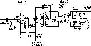 I.F. m VOLTMETER . Tl-J.W. MILLCP 01г-СЗ NOTE: ALL CAPACIWRS IN JUF UNLESS OTHERWISE NCfTED ALL RESISTORS O.S WATT UNLESS OTHERWISE NOTED Figure 23 NBFM ADAPTER FOR 455-KC. I-F SYSTEM volts peak for the maximum deviation which can be handled by a conventional 455kc. i-f system. The unit may be tuned by placing a high resistance d-c voltmeter across Ri and tuning the trimmers of the i-f transformer for maximum voltage when an unmodulated signal is injected into the i-f strip of the receiver. The voltmeter should next be connected across the audio оифи1 terminal of the discriminator. The receiver is now tuned back and forth a-cross the frequency of the incoming signal, and the movement of the voltmeter noted. When the receiver is exactly tuned on the signal the voltmeter reading should be zero. When the receiver is tuned to one side of center, the voltmeter reading should increase to a maximum value and then decrease gradually to zero as the signal is tuned out of the passband of the receiver. When the receiver is tuned to the other side of the signal the voltmeter should increase to the same maximum value but in the opposite direction or polarity, and then fall to zero as the signal is tuned out of the passband. It may be necessary to make small adjustments to and Cj to make the voltmeter read zero when the signal is tuned in the center of the passband. 16-5 Radio Teletype The teletype machine is an electric typewriter that is stimulated by d.c. pulses originated by the action of a second machine. The pulses may be transmitted from one machine to another by wire, or by a radio signal. When radio transmission is used, the system is termed radio teletype (RTTY). The d.c. pulses that comprise the teletype signal may be converted into three basic types of emission suitable for radio transmission. These are; 1- Frequency shift keying (FSK), designated as FI emission; 2- Hake-break keying (MBK),designated as Al emission, and; 3- Audio frequency shift keying (AFSK), designated as F2 emission. Frequency shift keying is obtained by varying the transmitted frequency of the radio signal a fixed amount (usually 850 cycles) during the keying process. The shift is accomplished in discrete intervals designated mark and space. Both types of intervals convey information to the teletype printer. Make-break keying is analogous to simple c-w transmission in that the radio carrier conveys information by changing from an off to an on condition. Early RTTY circuits employed MBK equipment, which is rapidly becoming obsolete since it is inferior to the frequency shift system. Audio frequency shift keying employs a steady radio carrier modulated by an audio tone that is shifted in frequency according to the RTTY pulses. Other forms of information transmission may be employed by a RTTY system which also encompass the translatitm of RTTY pulses into r-f signals. Teletype The RTTY code consists of Coding the 26 letters of the alphabet, the space, the line feed, the carriage return, the bell, the upper case shift, and the lower case shift; making a total of 32 coded groups. Numerals, punctuation, and symbols may be taken care of in the case shift, since all transmitted letters are capitals. The FSK system normally employs the higher radio frequency as the mark, and the lower frequency as the space. This relationship holds true in the AFSK system also. The lower audio frequency (mark) is normally 2125 cycles and the higher audio tone (space) is 2975 cycles, giving a frequency difference of 850 cycles. The Teletype A simple FSK teletype system System may be added to any c-w trans- mitter. The teletype keyboard prints the keyed letters on a tape, and at the same time generates the electrical code group that describes the letter. The d.c. pulses are impressed upon a distributor imit which arranges the typing and spacing pulses in proper sequence. The resulting series of impulses ate applied to the transmitter frequency control device, which may be a reactance modulator, actuated by a polar relay. The received signal is hetrodyned against a beat oscillator to provide the two audio tones which are limited in amplitude and passed through audio filters to separate them. Rectification of the tones permits operation of a polar relay which can provide d.c. pulses suitable for operation of the tele-typewriter. CHAPTER SEVENTEEN Sideband Transmission While single-sideband transmission (SSB) has attracted significant interest on amateur frequencies only in the past few years, the principles have been recognized and put to use in various commercial applications for many years. Expansion of single-sideband for both commercial and amateur communication has awaited the development of economical components possessing the required characteristics (such as sharp cutoff filters and high stability crystals) demanded by SSB techniques. The availability of such components and precision test equipment now makes possible the economical testing, adjustment and use of SSB equipment on a wider scale than before. Many of the seemingly insurmountable obstacles of past years no longer prevent the amateur from achieving the advantages of SSB for his class of operation. 17-1 Commercial Applications of SSB Before discussion of amateur SSB equipment, it is helpful to review some of the commercial applications of SSB in an effort to avoid problems that are already solved. The first and only large scale use of SSB has been for multiplexing additional voice circuits on long distance telephone toll wires. Carrier systems came into wide use during the 30s, accompanied by the development of high Q toroids and copper oxide ring modulators of controlled characteristics. The problem solved by the carrier system was that of translating the 300-3000 cycle voice band of frequencies to a higher frequency (for example, 40.3 to 43-0 kc.) for transmission on rhe toll wires, and then to reverse the translation process at the receiving terminal. It was possible in some short-haul equipment to amplitude modulate a 40 kilocycle carrier with the voice frequencies, in which case the resulting signal would occupy a band of frequencies between 37 and 43 kilocycles. Since the transmission properties of wires and cable deteriorate rapidly with increasing frequency, most systems required the bandwidth conservation characteristics of single-sideband transmission. In addition, the carrier wave was generally suppressed to reduce the power handling capability of the repeater amplifiers and diode modulators. A substantial body of literature on the components and circuit techniques of SSB has been generated by the large and continuing development effort to produce economical carrier telephone systems. The use of SSB for overseas radiotelephony has been practiced for several years though the number of such circuits has been numerically small. However, the economic value of such circuits has been great enough to warrant elaborate station equipment. It is from these stations that the impression has been obtained that SSB is too complicated for all but a corps of engineers and technicians to handle. Components such as lattice filters with 40 or more crystals have suggested astronomical expense. ® LOWE я SIDEBAND CARRIER FREQ. UPPER SIDEBAND 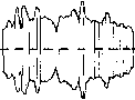 FREQUENCY SPECTRUM WITH COMPLEX MODULATING WAVE CARRIER ENVELOPE WITH COMPLEX MODULATING WAVE Figure 1 REPRESENTATION OF A CONVENTIONAL AM SIGNAL More recently, SSB techniques have been used to multiplex large numbers of voice channels on a microwave radio band using equipment principally developed for telephone caj:-rier applications. It should be noted that all production equipment employed in these services uses the filter method of generating the single-sideband signal, though there is a wide variation in the types of filters aaually used. The SSB signal is generated at a low frequency and at a low level, and then translated and linearly amplified to a high level at the operating frequency. Considerable development effort has been expended on high level phasing type transmitters wherein the problems of linear amplification are exchanged for the problems of accurately controlled phase shifts. Such equipment has featured automatic tuning circuits, servo-driven to facilitate frequency changing, but no transmitter of this type has been sufficiently attractive to warrant appreciable production. 17-2 Derivation of Single-Sideband Signals The single-sideband method of communication is, essentially, a procedure for obtaining more efficient use of available frequency spectrum and of available transmitter capability. As a starting point for the discussion of single-sideband signals, let us take a conventional AM signal, such as shown in figure 1, as representing the most common method for transmitting complex intelligence such as voice or music. It will be noted in figure 1 that there are three distinct portions to the signal: the carrier, and the upper and the lower sideband group. These three portions always are present in a conventional AM signal. Of all these portions the carrier is the least necessary and the most expensive to transmit. It is an actual fact, and it can be proved mathematically (and physically with a highly selective receiver) that the carrier of an AM signal remains unchanged in amplitude, whether it is being modulated or not. Of course the carrier appears to be modulated when we observe the modulated signal on a receiving system or indicator which passes a sufficiently wide band that the carrier and the modulation sidebands are viewed at the same time. This apparent change in the amplitude of the carrier with modulation is simply the result of the sidebands beating with the carrier. However, if we receive the signal on a highly selective receiver, and if we modulate the carrier with a sine wave of 3000 to 5000 cycles, we will readily see that the carrier, or either of the sidebands can be tuned in separately, the carrier amplitude, as observed on a signal strength meter, will remain constant, while the amplitude of the sidebands will vary in direct proportion to the modulation percentage. Elimination of the Carrier and One Sideband It is obvious from the previous discussion that the carrier is superfluous so far as the transmission of intelligence is concerned. It is obviously a convenience, however, since it provides a signal at the receiving end for the sidebands to beat with and thus to reproduce the original modulating signal. It is equally true that the transmission of both sidebands under ordinary conditions is superfluous since identically the same intelligence is contained in both sidebands. Several systems for carrier and sideband elimination will be discussed in this chapter. Power Advantage Single sideband is a very of SSB over AM efficient form of voice communication by radio. The amount of radio frequency spectrum occupied can be no greater than the frequency range of the audio or speech signal transmitted, whereas other forms of radio transmission require from two to several times as much spectrum space. The r-f power in the transmitted SSB signal is directly proportional to the power in the original audio signal and no strong carrier is transmitted. Except for a weak pilot carrier present in some commercial usage, there is no r-f output when there is no audio input. The power output rating of a SSB transmitter is given in terms of peak envelope power (PEP). This may be defined as the r-m-s power at the crest of the modulation envelope. The peak envelope power of a conventional amplitude modulated signal at 100% modulation is four times the carrier power. The average power input to a SSB transmitter is therefore a very small fraction of the power input to a conventional amplitude modulated transmitter of the same power rating. Single sideband is well suited for long-range communications because of its spectrum and power economy and because it is less susceptible to the effects of selective fading and interference than amplitude modulation. The principal advantages of SSB arise from the elimination of the high-energy carrier and from further reduction in sideband power permitted by the improved performance of SSB under unfavorable propagation conditions. In the presence of narrow band man-made interference, the narrower bandwidth of SSB reduces the probability of destructive interference .A statistical study of the distribution of signals on the air versus the signal strength shows that the probability of successful communication will be the same if the SSB power is equal to one-half the power of one of the two a-m sidebands. Thus SSB can give from 0 to 9 db improvement under various conditions when the total sideband power is equal in SSB and a-m. In general, it may be assumed that 3 db of the possible 9 db advantage will be realized on the average contact. In this case, the SSB power required for equivalent performance is equal to the power in one of the a-m sidebands. For example, this would rate a 100-watt SSB and a 400 watt (carrier) a-m transmitter as having equal performance. It should be noted that in this comparison it is assumed that the receiver bandwidth is just sufficient to accept the transmitted intelligence in each case. To help evaluate other methods of comparison the following points should be considered. In conventional amplitude modulation two sidebands are transmitted, each having a peak envelope power equal to Vi-carrier power. For example, a 100-watt a-m signal will have 25-watt peak envelope power in each sideband, or a total of 50 watts. When the receiver detects this signal, the voltages of the two sidebands are added in the detector. Thus the detector output voltage is equivalent to that of a 100-watt SSB signal. This method of comparison says that a 100 watt SSB transmitter is just equivalent to a 100-watt a-m transmitter. This assumption is valid only when the receiver bandwidth used for SSB is the same as that required for amplitude modulation 4000 КС. 4O04KC 3996 КС. 4000 ЛС АиОЮ SPECTRUM SSB SPECTRUM SSB SPECTRUM (UPPER StOEBANO) {LOWER SIDEBAND ) ® ® © Figure 2 RELATIONSHIP OF AUDIO AND SSB SPECTRUMS The single sideband components are tiie same as the original audio components except that the frequency of each is raised by the frequency of the carrier. The relative amplitude of the various components remains the same. (e.g., 6 kilocycles), when there is no noise or interference other than broadband noise, and if the a-m signal is not degraded by propagation. By using half the bandwidth for SSB reception (e.g., 3 kilocycles) the noise is reduced 3 db so the 100 watt SSB signal becomes equivalent to a 200 watt carrier a-m signal. It is also possible for the a-m signal to be degraded another 3 db on the average due to narrow band interference and poor propagation conditions, giving a possible 4 to I power advantage to the SSB signal. It should be noted that 3 db signal-to-noise ratio is lost when receiving only one sideband of an a-m signal. The narrower receiving bandwidth reduces the noise by 3 db but the 6 db advantage of coherent detection is lost, leaving a net loss of 3 db. Poor propagation will degrade this one sideband reception of an a-m signal less than double sideband reception, however. Also under severe narrow band interference conditions (e.g., an adjacent strong signal) the ability to reject all interference on one side of the carrier is a great advantage. The Nature of a The nature of a single SSB Signal sideband signal is easily visualized by noting that the SSB signal components are exactly the same as the original audio components except that the frequency of each is raised by the frequency of the carrier. The relative amplitude of the various components remains the same, however. (The first statement is only true for the upper sideband since the lower sideband frequency components are the difference between the carrier and the original audio signal). Figure 2A, B, and С shows how the audio spectrum is simply moved up into the radio spectrum to give the upper sideband. The lower sideband is the same except inverted, as shown in figure 2C. Either sideband may be used. It is apparent that the carrier frequency 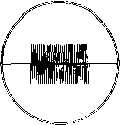 single tone 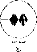 Figure 3 A SINGLE SINE WAVE TONE INPUT TO A SSB TRANSMITTER RESULTS IN A STEADY SINGLE SINE WAVE R-F OUTFIT (A). TWO AUDIO TONES OF EQUAL AMPLITUDE BEAT TOGETHER TO PRODUCE HALF-SINE WAVES AS SHOWN IN (B). of a SSB signal can only be changed by adding or subtracting to the original carrier frequency. This is done by heterodyning, using converter or mixer circuits similar to those employed in a superheterodyne receiver. It is noted that a single sine wave tone input to a SSB transmitter results in a single steady sine wave r-f ouput, as shown in figure ЗА. Since it is difficult to measure the performance of a linear amplifier with a single tone, it has becorne standard practice to use two tones of equal amplitude for test purposes. The two radio frequencies thus produced beat together to give the SSB envelope shown in figure 3B. This figure has the shape of half sine waves, and from one null to the next represents one full cycle of the difference frequency. How this envelope is generated is shown more fully in figures 4A and 43. fi and h represent the two tone signals. When a vector representing the lower frequency tone signal is used as a reference, the other vector rotates around it as shown, and this action 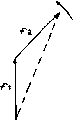 frequency fl of carrier Figure 4 VECTOR REPRESENTATION OF TWO-TONE SSB ENVELOPE 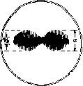  Figure 5 TWO-TONE SSB ENVELOPE WHEN ONE TONE HAS TWICE THE AMPLITUDE OF THE OTHER. Figure 6 THREE-TONE SSB ENVELOPE WHEN EQUAL TONES OF EQUAL FREQUENCY SPACINGS ARE USED. generates the SSB envelope When the two vectors are exactly opposite in phase, the output is zero and this causes the null in the envelope. If one tone has twice the amplitude of the other, the envelope shape is shown in figure 5. Figure б shows the SSB envelope of three equal tones of equal frequency spacings and at one particular phase relationship. Figure 7A shows the SSB envelope of four equal tones with equal frequency spacings and at one particular phase relationship. The phase relationships chosen are such that at some instant the vectors representing the several tones are all in phase. Figure 7B shows a SSB envelope of a square wave. Л pure square wave requires infinite bandwidth, so its SSB envelope requires infinite amplitude. This emphasizes the point that the SSB envelope shape is not the same as the original audio wave shape, and usually bears no similarity to it. This is because the percentage difference between the radio frequencies is very small, even though one audio tone may be several times the other in terms of frequency. Speech clipping as used  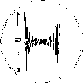 ® Figure 7A FOUR TONE SSB ENVELOPE when equaf tones with equof frequency spacings ore vsed ® Figure 7В SSB ENVELOPE OF A SQUARE WAVE. Peak of wave reaches infinite amplitude. 1 ... 29 30 31 32 33 34 35 ... 80 |
|
© 2026 AutoElektrix.ru
Частичное копирование материалов разрешено при условии активной ссылки |