 |
 |
 |
| Главная Журналы Популярное Audi - почему их так назвали? Как появилась марка Bmw? Откуда появился Lexus? Достижения и устремления Mercedes-Benz Первые модели Chevrolet Электромобиль Nissan Leaf |
Главная » Журналы » Simple coaxial reflectometer 1 ... 31 32 33 34 35 36 37 ... 80 HANDBOOK Frequency Conversion 341 6BE6 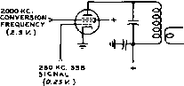 TUNE TO SELECT Z000- -2S0°22S0KC. OR 2000-MO = 17SO KC. Figure 27 PEMTAGRID MIXER CIRCUIT FOR SSB FREQUENCY CONVERSION quency into tlie # 3 grid. Tliis is tlie reverse of the usual grid connections, but it offers about 10 db improvement in distortion. The plate circuit is tuned to select the desired output frequency product. Actually, the output of the mixer tube contains all harmonics of the two input signals and all possible combinations of the sum and difference frequencies of all the harmonics. In order to avoid distortion of the SSB signal, it is fed to the mixer at a low level, such as 0.1 to 0.2 volts. The conversion frequency is fed in at a level about 20 db higher, or about 2 volts. By this means, harmonics of the incoming SSB signal generated in the mixer tube will be very low. Usually the desired output frequency is either the sum or the difference of the SSB generator carrier frequency and the conversion frequency. For example, using a SSB generator carrier frequency of 250 kc. and a conversion injection frequency of 2000 kc. as shown in figure 27, the output may be tuned to select either 2250 kc. or 1750 kc. Not only is it necessary to select the desired mixing product in the mixer output but also the undesired products must be highly attenuated to avoid having spurious output signals from the transmitter. In general, all spurious signals that appear within the assigned frequency channel should be at least 60 db below the desired signal, and those appearing outside of the assigned frequency channel at least 80 db below the signal level. When mixing 250 kc. with 2000 kc. as in the above example, the desired product is the 2250 kc. signal, but the 2000 kc. injection frequency will appear in the output about 20 db stronger than the desired signal. To reduce it to a level 80 db below the desired signal means that it must be attenuated 100 db. The principal advantage of using balanced modulator mixer stages is that the injection frequency theoretically does not appear in the output. In practice, when a considerable frequency range must be tuned by the balanced modulator and it is not practical to trim the ~E-1(-- 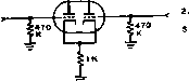 SSB OUTPUT о VOLT CONVERSION ICNAL 0.2 VOLT SICNAL INPUT Figure 28 TWIN TRIODE MIXER CIRCUIT FOR SSB FREQUENCY CONVERSION push-pull circuits and the tubes into exact amplitude and phase balance, about 20 db of injection frequency cancellation is all that can be depended upon. With suitable trimming adjustments the cancellation can be made as high as 40 db, however, in fixed frequency circuits. The Twin Triode Mixer The mixer circuit shown In figure 28 has about 10 db lower distortion than the conventional 6BE6 converter tube. It has a lower voltage gain of about unity and a lower output impedance which loads the first tuned circuit and reduces its selectivity. In some applications the lower gain is of no consequence but the lower distortion level is Important enough to warrant its use in high performance equipment. The signal-to-distortion ratio of this mixer is of the order of 70 db compared to approximately 60 db for a 6BE6 mixer when the level of each of two tone signals is 0.5 volt. With stronger signals, the бВЕб distortion increases very rapidly, whereas the 12AU7 distortion is much better comparatively. eASes 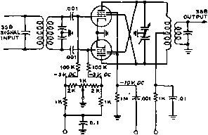 -BIAS CARRIER + 120 V. IN AT5MA. Figure 29 BALANCED MODULATOR CIRCUIT FOR SSB FREQUENCY CONVERSION 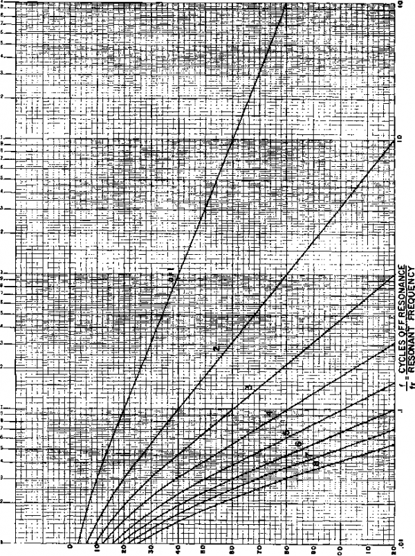 Figure 30 RESPONSE OF N NUMBER OF TUNED CIRCUITS, ASSUMING EACH CIRCUIT Q IS 50 HANDBOOK Frequency Conversion 343 In practical equipment where the injection frequency is variable and trimming adjustments and tube selection cannot be used, it may be easier and more economical to obtain this extra 20 db of attenuation by using an extra tuned circuit in the output than by using a balanced modulator circuit. A balanced modulator circuit of interest is shown in figure 29, providing a minimum of 20 db of carrier attenuation with no balancing adjustment. Selective Tuned Circuits The selectivity requirements of the tuned circuits following a mixer stage often become quite severe. For example, using an input signal at 250 kc and a conversion injection frequency of 4000 kc. the desired output may be 4250 kc Passing the 4250 kc. signal and the associated sidebands without attenuation and realizing 100 db of attenuation at 4000 kc. (which is only 250 kc. away) is a practical example. Adding the requirement that this selective circuit must tune from 2250 kc to 4250 kc. further complicates the basic requirement. The best solution is to cascade a number of tuned circuits. Since a large number of such circuits may be required, the most practical solution is to use permeability tuning, with the circuits tracked together. An example of such circuitry is found in the Collins KWS-1 sideband transmitter. If an amplifier tube is placed between each tuned circuit, the overall response will be the sum of one stage multiplied by the number of stages (assuming identical tuned circuits). Figure 30 is a chart which may be used to determine the number of tuned circuits required for a certain degree of attenuation at some nearby frequency. The Q of the circuits is assumed to be 50, which is normally realized in small permeability tuned coils. The number of tuned circuits with a Q of 50 required for providing 100 db of attenuation at 4000 kc. while passing 4250 kc. may be found as follows: Af is 4250-4000=250 kc fr is the resonant frequency, 4250 kc. and -= 250 4250 = 0.059 The point on the chart where .059 intersects 100 db is between the curves for 6 and 7 tuned circuits, so 7 tuned circuits are required. Another point which must be considered in practice is the tuning and tracking error of the circuits. For example, if the circuits were actually tuned to 4220 kc. instead of 4250 kc, Af 220 the -would be-22o 0.0522. Checking the curves shows that 7 circuits would just barely provide 100 db of attenuation. This illustrates the need for very accurate tuning and tracking in circuits having high attenuation properties. Coupled Tuned When as many as 7 tuned Circuits circuits are required for pro- per attenuation, it is not necessary to have the gain that 6 isolating amplifier tubes would provide. Several vacuum tubes can be eliminated by using two or three coupled circuits between the amplifiers. With a coefficient of coupling between circuits 0.5 of critical coupling, the overall response is very nearly the same as isolated circuits. The gain through a pair of circuits having 0-5 coupling is only eight-tenths that of two critically coupled circuits, however. If critical coupling is used between two tuned circuits, the nose of the response curve is broadened and about 6 db is lost on the skirts of each pair of critically coupled circuits. In some cases it may be necessary to broaden the nose of the response curve to avoid adversely affecting the frequency response of the desired passband. Another tuned circuit may be required to make up for the loss of attenuation on the skirts of critically coupled circuits. Frequency Conversion The example in the Problems previous section shows the difficult selectivity problem encountered when strong undesired signals appear near the desired frequency. A high frequency SSB transmitter may be required to operate at any carrier frequency in the range of 1.75 Mc. to 30 Mc. The problem is to find a practical and economical means of heterodyning the generated SSB frequency to any carrier frequency in this range. There are many modulation products in the output of the mixer and a frequency scheme must be found that will not have undesired output of appreciable amplitude at or near the desired signal. When tuning across a frequency range some products may cross over the desired frequency. These undesired crossover frequencies should be at least 60 db below the desired signal to meet modern standards. The amplitude of the undesired products depends upon the particular characteristics of the mixer and the particular order of the product. In general, most products of the 7th order and higher will be at least 60 db down. Thus any cross- FROM SSB CENEftATOft CAIN CONTROL PREAMPLIFIER -SIGNAL TO DISTORTION (S/D) RATION 5р-4я 4р-Э, 3p-aq 2р-ч 2я-р 34.-2i 4.1.-ЭР £<г4р Figure 31 SSB DISTORTION PRODUCTS, SHOWN UP TO NINTH ORDER over frequency lovser than the 7th must be avoided since there is no way of attenuating them if they appear within the desired pass-band. The General Electric Ham News, volume 11 #6 of Nov.-Dec., 1956 covers the subject of spurious products and incorporates a mix-selector chart that is useful in determining spurious products for various different mixing schemes. In general, for most applications when the intelligence bearing frequency is lower than the conversion frequency, it is desirable that the ratio of the two frequencies be between 5 to 1 and 10 to 1. This is a compromise between avoiding low order harmonics of this signal input appearing in the output, and minimizing the selectivity requirements of the circuits following the mixer stage. 17-6 Distortion Products Due to Nonlinearity of R-F Amplifiers When the SSB envelope of a voice signal is distorted, a great many new frequencies are generated. These represent all of the possible combinations of the sum and difference frequencies of all harmonics of the original frequencies. For purposes of test and analysis, two equal amplitude tones are used as the SSB audio source. Since the SSB radio frequency amplifiers use tank circuits, all distortion products are filtered out except those which lie close to the desired frequencies. These are all odd order products; third order, fifth order, etc.. The third order products are 2p-q and 2q-p where p and q represent the two SSB r-f tone frequencies. The fifth order products are 3p-2q and 3q-2p. These and some higher order products are shown in figure 31. It should be noted that the frequency spacings are always equal to the difference frequency of the two original tones. Thus when a SSB amplifier is badly over- PQWER amplifier stage control bias r-f from p-a plate CIRCUIT ft-f rectifier delay bias voltage from power supply Figure 32 BLOCK DIAGRAM OF AUTOMATIC LOAD CONTROL (A.L.C.) SYSTEM loaded, these spurious frequencies can extend far outside the original channel width and cause an unintelligible splatter type of interference in adjacent channels. This is usually of far more importance than the distortion of the original tones with regard to intelligibility or fidelity. To avoid interference in another channel, these distortion products should be down at least 40 db below adjacent channel signal. Using a two-tone test, the distortion is given as the ratio of the amplitude of one test tone to the amplitude of a third order product. This is called the signal-to-distortion ratio (S/D) and is usually given in decibels. The use of feedback r-f amplifiers make S/D ratios of greater than 40 db possible and practical. Automatic Two means may be used to Load Control keep the amplitude of these distortion products down to acceptable levels. One is to design the amplifier for excellent linearity over its amplitude or power range. The other is to employ a means of limiting the amplitude of the SSB envelope to the capabilities of the amplifier. An automatic load control ssytem (ALC) may be used to accomplish this result. It should be noted that the r-f wave shapes of the SSB signal are always sine waves because the tank circuits make them so. It is the change in gain with signal level in an amplifier that distorts the SSB envelope and generates unwanted distortion products. An ALC system may be used to limit the input signal to an amplifier to prevent a change in gain level caused by excessive input level. The ALC system is adjusted so the power amplifier is operating near its maximum power capability and at the same time is protected from being over-driven. In amplitude modulated systems it is common to use speech compressors and speech clipping systems to perform this function. These methods are not HANDBOOK Distortion Products 345 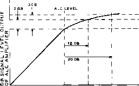 DB SIGNAL LEVEL INPUT Figure 33 PERFORMANCE CURVE OF A.L.C. CIRCUIT equally useful in SSB. The reason for this is that the SSB envelope is different from the audio envelope and the SSB peaks do not necessarily correspond with the audio peaks as explained earlier in this chapter. For this reason a compressor of some sort located betvseen the SSB generator and the power amplifier is most effective because it is controlled by SSB envelope peaks rather than audio peaks. Such a SSB signal compressor and the means of obtaining its control voltage comprises a satisfactory ALC system. The ALC Circuit A block diagram of an ALC circuit is shown in figure 32. The compressor or gain control part of this circuit uses one or two stages of remote cutoff tubes such as бВАб, operating very similarly to the intermediate frequency stages of a receiver having automatic volume control. The grid bias voltage which controls the gain of the tubes is obtained from a voltage detector circuit connected to the power amplifier tube plate circuit. A large delay bias is used so that no gain reduction takes place until the signal is nearly up to the full power capability of the amplifier. At this signal level, the rectified output overcomes the delay bias and the gain of the preamplifier is reduced rapidly vsith increasing signal so that there is very little rise in output power above the threshold of gain control. When a signal peak arrives that would normally overload the power amplifier, it is de-sireable that the gain of the ALC amplifier be reduced in a few milliseconds to a value where overloading of the power amplifier is overcome. After the signal peak passes, the gain should return to the normal value in about one-tenth second. These attack and release times are commonly used for voice communications. For this type of work, a dynamic range of at least 10 db is desirable. Input peaks as high as 20 db above the threshold of compression should not cause loss of control although some increase in distortion in the upper range of compression can be tolerated because peaks in this range are infrequent. Another limitation is that the preceding SSB generator must be capable of passing signals above full power output by the amount of compression desired. Since the signal level through the SSB generator should be maintained within a limited range, it is unlikely that more than 12 db ALC action will be useful. If the input signal varies more than this, a speech compressor should be used to limit the range of the signal fed into the SSB generator. Figure 33 shows the effectiveness of the ALC in limiting the output signal to the capabilities of the povser amplifier. An adjustment of the delay bias will place the threshold of compression at the desired power output. Figure 34 shows a simplified schematic of an ALC system. This ALC uses two variable gain am- Figure 34 SIMPLIFIED SCHEMATIC OF AUTOMATIC LOAD CONTROL AMPLIFIER. OPERATING POINT OF ALC CIRCUIT MAY BE SET BY VARYING BLOCKING BIAS ON CATHODE OF 6X4 SIGNAL RECTIFIER SSB OUTPUT TO P-A grid INPUT* 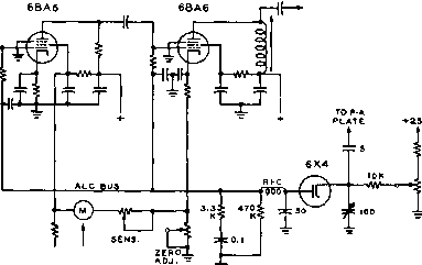 ггк Л. ALC COMPRESSION INDICATOR R-F л SOURCE SOURCE 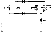 Figure 35 SSB JR. MODULATOR CIRCUIT R-f and A-F sources ore applied in to balanced modulator. series plifier stages and the maximum overall gain is about 20 db. A meter is incorporated which is calibrated in db of compression. This is useful in adjusting the gain for the desired amount of load control. A capacity voltage divider is used to step down the r-f voltage at the plate of the amplifier tube to about 50 volts for the ALC rectifier. The output of the ALC rectifier passes through R-C networks to obtain the desired attack and release times and through r-f filter capacitors. The З.ЗК resistor and 0-1 fiid. capacitor across the rectifier output stabilizes the gain around the ALC loop to prevent motor-boating. 17-7 Sideband Exciters Some of the most popular sideband exciters in use today are variations of the simple phasing circuit introduced in the November, 1950 issue of General Electric Ham News. Called the SSB, Jr., this simple exciter is the basis for many of the phasing transmitters now in use. Employing only three tubes, the SSB, Jr. is a classic example of sideband generation reduced to its simplest form. The SSB, Jr. This phasing exciter employs audio and r-f phasing circuits to produce a SSB signal at one spot frequency. The circuit of one of the balanced modulator stages is shown in figure 35- The audio signal and r-f source are applied in series to two germanium diodes serving as balanced modulators XTAL OR L 19Д117 Тг V.F.D. 2 Ли HEO-WH/TE - PHASE г SHIFT NETWORK 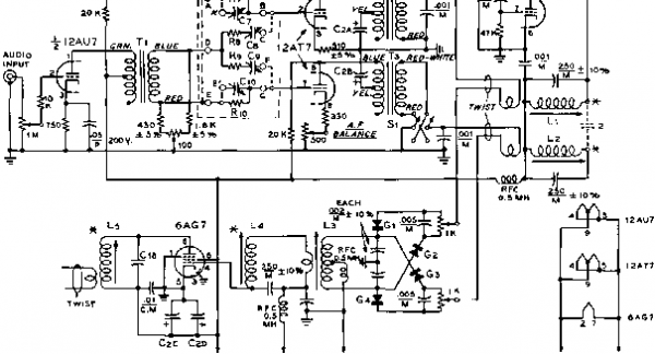 R.F. OUTPUT C-t-, B- C£A.B.C,D = EACH SECTION гО JUF. 4S0 V. 07=2430 JJJUFD (.002iJFD MICA ±5* WITH Ce =4660 JJUFD. (.00*3 WFD MICA ±S)b WITH C9 = 121S JUJUFD.(,001 iJFD MICA WITH ClO=607.bJJUFD (SOOUIJFO MICA ±5% WITH Cie=3S0miFD eoOV.MICA ±10* (iSO JJJUFD R7,RiO= 133.300 OHMS, 1/2 WATT ±1% Re,R9= 100,000 OHMS, 1/2 WATT ±1% Ti-STANQOR A-S3C TRANSFORMER. Т2,ТЗ= arc />-38A TRANSFORMER. S1 = DPDT TOCCLE SWITCH ELECTROLYTIC Gl, 2.3,4= 1N52 GERMANIUM DIODE OR EQUIVALENT 170-780 UUFD TRIMMER) Ll, La = 33T, N 2lE,WlftE CLOSEWOUND ON MILLEN Ы' 90Лй 170-780 JJIUFO TRIMMER) I RON CORE ADJUSTABLE SLUG COi L FOR M. LINK OF в 50-380JUUFDTRIMMER) TURNS OF HOOKUP WIRE WOUND ON OPEN END. S-ieOJUJUFDTHIMMEH)l3=ieT. N 19 E. WIR E SPACED TO FI LL MILLEN N 69046 AND lOOJLUJFD PARALLEL) COIL FORM. TAP AT в TURNS. LINK OF 1 TURN AT CENTER. l4=SAME AS Ll EXCEPT NO LINK USED. L5= 28 T. 0FN 19 E. WIRE. LINK ON END TO MATCH LOAD. (4 TURN LINK MATCHES 72 OHM LOAD) K- = MOUNTING END OF COILS, Figure 36 SCHEMATIC, SSB, JR. having a push-pull output circuit tuned to the r-f carrier frequency. The modulator drives a linear amplifier directly at the output frequency. The complete circuit of the exciter is shown in figure 36. The first tube, a 12AU7, is a twin-triode serving as a speech amplifier and a crystal oscillator. The second tube is a 12AT7, acting as a twin channel audio amplifier following the phase-shift audio network. The linear amplifier stage is a 6AG7, capable of a peak power output of 5 watts. Sideband switching is accomplished by the reversal of audio polarity in one of the audio channels (switch Si)> and provision is made for equalization of gain in the audio channels (Ris)- This adjustment is necessary in order to achieve normal sideband cancellation, which may be of the order of 35 db or better. Phase-shift network adjustment may be achieved by adjusting potentiometer Rs. Stable modulator balance is achieved by the balance potentiometers Rie and Rn in conjunction with the germanium diodes. The SSB, Jr. is designed for spot frequency operation. Note that when changing frequency Ll, L2, L3, Ll, and L5 should be readjusted, since these circuits constitute the tuning adjustments of the rig. The principal effect of mistuning L3, L4, and Ls will be lower output. The principal effect of mistuning L2, however, will be degraded sideband suppression. Power requirements of the SSB, Jr. are ЗОО olts at 60 ma., and 10.5 volts at 1 ma. Under load the total plate current will rise to about 80 ma. at full level with a single tone input. With speech input, the total current will rise from the resting value of 60 ma. to about 70 ma., depending upon the voice waveform. The Ten-A The Model 10-A phasing ex-Exciter citer produced by Central Electronics, Inc. is an advanced version of the SSB, Jr. incorporating extra features such as VFO control, voice operation, and multi-band operation. A simplified schematic of the Model 10A is shown in figure 37. The 12AX7 two stage speech amplifier excites a transformer coupled V-12BH7 low impedance driver stage and a voice operated (VOX) relay system employing a 12AX7 and a 6AL5. A transformer coupled 12AT7 follows the audio phasing network, providing two audio channels having a 90-degree phase difference. A simple 90-degree r-f phase shift network in the plate circuit of the 9 Mc. crys- tal oscillator stage works into the matched, balanced modulator consisting of four 1N48 diodes. The resulting 9 Mc. SSB signal may be converted to the desired operating frequency in a 6BA7 mixer stage. Eight volts of r-f from an external v-f-o injected on grid #1 of the 6BA7 is sufficient for good conversion efficiency and low distortion. The plate circuit of the 6BA7 is tuned to the sum or difference mixing frequency and the resulting signal is amplified in a 6AG7 linear amplifier stage. Two tweet traps are incorporated in the 6BA7 stage to reduce unwanted responses of the mixer which are apparent when the unit is operating in the 14 Mc band. Band-changing is accomplished by changing coils Ls and Ls and the frequency of the external mixing signal. Maximum power output is of the order of 5 watts at any operating frequency. A Simple 80 Meter A SSB exciter employ-Phasing Exciter in§ r-f and audio phasing circuits is shown in figure 38. Since the r-f phasing circuits are balanced only at one frequency of operation, the phasing exciter is necessarily a single frequency transmitter unless provisions are made to re-balance the phasing circuits every time a frequency shift is made. However for mobile operation, or spot frequency operation a relatively simple phasing exciter may be made to perform in a satisfactory manner. A 12AU7 is employed as a Pierce crystal oscillator, operating directly on the chosen SSB frequency in the 80 meter band- The second section of this tube is used as an isolation stage, with a tuned plate circuit, Li. The output of the oscillator stage is link coupled to a 90° r-f phase-shift network wherein the audio signal from the audio phasing network Is combined with the r-f signals. Carrier balance is accomplished by adjustment of the two 1000 ohm potentiometers in the r-f phase network. The output of the f-f phasing network is coupled through Lj to a single 6CL6 linear amplifier which delivers a 3 watt peak SSB signal on 80 meters. A cascade 12AT7 and a single 6C4 comprise the speech amplifier used to drive the audio phase shift network. A small inter-stage transformer is used to provide the necessary 180° audio phase shift required by the network. The output of the audio phasing network is coupled to a 12AU7 dual cathode follower which provides the necessary low impedance circuit to match the r-f phasing network. A double- AUDIO PHASE SHIFT NETWORK PS-1 I-------1 12AX7 Cl.,.005 1л 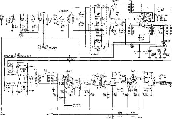 -VOICE CONTROL - RELAY CONTACTS 12AU7 j -- OU Ll, L2,L3= Z4T #гг £, on XR-SO FORM {o.S ai4.) V.\-LINK COILS ARE 4T. EACH. Di-D4= 1N71 12AT7 MIC, гоо к .001 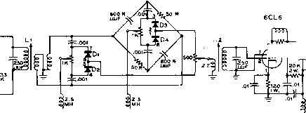 -iW-70K 25K-±r -l(-r- .001 .1 NOTE: LIHLESS OTHER WISE SPECIFIED; ALL RESISTORS 0.5 WATT ALL CAPACITORS IN JJF. ASTERISK AFTER CAPACITOR OR RESISTOR VALUE INDICATES PRECISION UNIT EXACT VALUE CRITICAL ONLY IN THAT IT SHOULD MATCH THE MATINS UNIT CLOSELY. SIDEBANO SELECTOR SWITCH   О О MILLEN AUOlO IN PHASE OUT SHIFT NETWORK О Jp0.25V.  1W. JW. Figure 38 SIMPLE 3.WATT PHASING TYPE SSB EXCITER pole double-throw switch in the output circuit of the cathode follower permits sideband selection. A Filter-Type Exciter for 80 and 40 Meters A simple SSB filter-type exciter employing the Collins mechanical filter illustrates many of the basic principles of sideband generation. Such an exciter is shown in figure 39. The exciter is designed for operation in the 80 or 40 meter phone bands and delivers sufficient output to drive a class ABi tetrode such as the 2E26, 807, or 6146. A conversion crystal may be employed, or a separate conversion v-f-o can be used as indicated on the schematic illustration. The exciter employs five tubes, exclusive of power supply. They are: 6U8 low frequency oscillator and r-f phase inverter, 6BA6 i-f amplifier, 6BA7 high frequency mixer, 6AG7 linear amplifier, and 12AU7 speech amplifier and cathode follower. The heart of the exciter is the balanced modulator employing two 1N81 germanium diodes and the 455 kc, 3500-cycle bandwidth mechanical filter. The input and output circuits of the filter are resonated to 455 kc. by means of small padding capacitors. A series-tuned Clapp oscillator covers the range of 452 kc. - 457 kc. permitting the carrier frequency to be adjusted to the 20 decibel points on the response curve of the fiher, as shown In figure 40. Proper r-f signal balance to the diode modulator may be obtained by adjustment of the padding capacitor In the cathode circuit of the triode section of the 6U8 r-f tube. Carrier balance is set by means of a 50K potentiometer placed across the balanced modulator. One half of a 12AU7 serves as a speech am-phfier delivering sufficient output from a high level crystal microphone to drive the second half of the tube as a low impedance cathode follower, which is coupled to the balanced modulator. The two 1N81 diodes act as an electronic switch, impressing a double sideband, suppressed-carrier signal upon the mechanical filter. By the proper choice of frequency of the beating oscillator, the unwanted sideband may be made to fall outside the pass-band of the mechanical filter. Thus a single sideband suppressed-carrier signal appears at the output of the filter. The 455 kc SSB signal is amplified by a бВАб pentode stage, and is then converted to a frequency in the 80 meter or 40 meter band by a 6BA7 mixer stage. Either a crystal or an external v-f-o may be used for the mixing signal. To reduce spurious signals, a double tuned 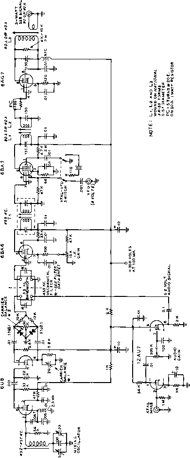
Figure 39 SCHEMATIC, FILTER-TYPE SSB EXCITER FOR 80 OR 40 METER OPERATION
455 458 457 45B FREQUENCY (KC.) Figure 40 THE TWENTY DB CARRIER POINTS ON THE FILTER CURVE 7fie beating oicillatar shaald be adjusted so that its frequency corresponds to the 20 db attenuation points of the mechanical filter passband. The carrier of the SSB signal is thus attenuated 20 db in addition to the inherent carrier attenuation of the balanced mixer. A total carrier attenuation of SO db is achieved. Unwanted sideband rejection is of the same order. 6BE6 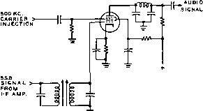 Figure 41 THE PRODUCT DETECTOR The above configuration resembles pentagrid converter circuit. (b) i -1 CYCLE OF- I LOWER SIOESAND UPPER SIDEBAND CARRIER FREO. FREQUENCY SPECTRUM WITH COMPLEX MODULATING WAVE 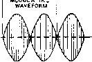 DOUBLE SIDE-BAND OUTPUT FROM BALANCED MODULATOR WITH SINE-WAVE MODULATION Figure 42 DOUBLE-SIDEBAND SUPPRESSED-CARRIER SIGNAL rhe envelope shown at В also is obtained on the oscilloscope when two audio frequencies of the same amplitude are ted to the input of a single-sideband transmitter. 1 ... 31 32 33 34 35 36 37 ... 80 |
||||||||||||||||||||||||||||||||||||||||||||||||||||||||||||||||||||||||||||||||||||||||||||||||||||||||||||||||||||||||||||||||||||||||||||||||||||||||||||||||||||||||||||
|
© 2026 AutoElektrix.ru
Частичное копирование материалов разрешено при условии активной ссылки |