 |
 |
 |
| Главная Журналы Популярное Audi - почему их так назвали? Как появилась марка Bmw? Откуда появился Lexus? Достижения и устремления Mercedes-Benz Первые модели Chevrolet Электромобиль Nissan Leaf |
Главная » Журналы » Simple coaxial reflectometer 1 ... 32 33 34 35 36 37 38 ... 80 transformer is placed between the mixer stage and the 6AG7 output stage. A maximum signal of 3 watts may be obtained from the 6AG7 linear amplifier. Selection of the upper or lower sideband is accomplished by tuning the 6U8 beating oscillator across the passband of the mechanical filter, as shown in figure 40. If the 80 meter conversion oscillator is placed on the low frequency side of the SSB signal, placing the 6U8 beating oscillator on the low frequency side of the passband of the mechanical filter will produce the upper sideband on 80 meters. When the beating oscillator is placed on the high frequency side of the passband of the mechanical filter the lower sideband will be generated on 80 meters. If the 80 meter conversion oscillator is placed on the high frequency side of the SSB signal, the sidebands will be reversed from the above. The variable oscillator should be set at approximately the 20 db suppression point of the passband of the mechanical filter for best operation, as shown in figure 40. If the oscillator is closer in frequency to the filter passband than this, carrier rejection will suffer. If the oscillator is moved farther away in frequency from the passband, the lower voice frequencies will be attenuated, and the SSB signal will sound high-pitched and tinny. A little practice in setting the frequency of the beating oscillator while monitoring the 80 meter SSB signal in the station receiver will quickly acquaint the operator with the proper frequency setting of the beating oscillator control for transmission of either sideband. If desired, an amplitude modulated signal with full carrier and one sideband may be transmitted by placing the 6U8 low frequency oscillator just inside either edge of the pass-band of the filter (designated AM point , figure 40). After the 6U8 oscillator is operating over the proper frequency range it should be possible to tune the beating oscillator tuning capacitor across the passband of the mechanical filter and obtain a reading on the S-meter of a receiver tuned to the filter frequency and coupled to the input grid of the бВАб i-f amplifier tube. The two carrier balance controls of the 6U8 phase inverter section should be adjusted for a null reading of the S-meter when the oscillator is placed in the center of the filter passband. The бВАб stage is now checked for operation, and transformed Ti aligned to the carrier frequency. It may be necessary to unbalance temporarily potentio- meter #2 of the 6U8 phase inverter in order to obtain a sufficiently strong signal for proper alignment of Ti. A conversion crystal is next plugged in the 6BA7 conversion oscillator circuit, and the operation of the oscillator is checked by monitoring the crystal frequency with a nearby receiver. The SSB carrier produced by the unbalance of potentiometer #2 should be heard at the proper sideband frequency in either the 80 meter or 40 meter band. The coupled circuit between the бВАу and the 6AG 7 is resonated for maximum carrier voltage at the grid of the amplifier stage. Care should be taken that this circuit is tuned to the sideband frequency and not to the frequency of the conversion oscillator. Finally, the 6AG7 stage is tuned for maximum output. When these adjustments have been completed, the 455 kc. beating oscillator should be moved just out of the passband of the mechanical filter. The 80 meter carrier will disappear. If it does not, there Is either energy leaking around the filter, or the amplifier stages are oscillating. Careful attention to shielding (and neutralization) should cure this difficulty. Audio excitation is now applied to the exciter, and the S-meter of the receiver should kick up with speech, but the audio output of the receiver should be unintelligible. As the frequency of the beating oscillator is adjusted so as to bring the oscillator frequency within the passband of the mechanical filter the modulation should become intelligible. A single sideband a.m. signal is now being generated-The BFO of the receiver should now be turned on, and the beating oscillator of the exciter moved out of the filter passband. When the receiver is correctly tuned, clean, crisp speech should be heard. The oscillator should be set at one of the 20 decibel points of the filter curve, as shown in figure 40 and all adjustments trimmed for maximum carrier suppression. 17-8 Reception of Single Sideband Signals Single-sideband signals may be received, after a certain degree of practice in the technique, in a quite adequate and satisfactory manner with a good communications receiver. However, the receiver must have quite good frequency stability both in the high-frequency oscillator and in the beat oscillator. Бог this reason, receivers which use a crystal-controlled first oscillator are likely to offer a greater degree of satisfaction than the more common type which uses a self-controlled oscillator. Beat oscillator stability in most receivers is usually quite adequate, but many receivers do not have a sufficient amplitude of beat oscillator injection to allow reception of strong SSB signals without distortion. In such receivers it is necessary either to increase the amount of beat-osciUator injection into the diode detector, or the manual gain control of the receiver must be turned down quite low. The tuning procedure for SSB signals is as follows: The SSB signals may first be located by tuning over the band with receiver set for the reception of c-w.; that is, with the manual gain at a moderate level and with the beat oscillator operating. By tuning in this manner SSB signals may be located when they are far below the amplitude of conventional AM signals on the frequency band. Then after a signal has been located, the beat oscillator should be turned off and the receiver put on a.v.c. Following this the receiver should be tuned for maximum swing of the S meter with modulation of the SSB signal. It will not be possible to understand the SSB signal at this time, but the receiver may be tuned for maximum deflection. Then the receiver is put back on manual gain control, the beat oscillator is turned on again, the manual gain is turned down until the background noise level is quite low, and the beat oscillator control is varied until the signal sounds natural. The procedure in the preceding paragraph may sound involved, but actually all the steps except the last one can be done in a moment. However, the last step is the one which will require some practice. In the first place, it is not known in advance whether the upper or lower sideband is being transmitted. So it will be best to start tuning the beat oscillator from one side of the pass band of the receiver to the other, rather than starting with the beat oscillator near the center of the pass band as is normal for c-w reception. With the beat oscillator on the wrong side of the sideband, the speech will sound inverted; that is to say that low-frequency modulation tones will have a high pitch and high-frequency modulation tones will have a low pitch- and the speech will be quite unintelligible. With the beat oscillator on the correct side of the sideband but too far from the correct position, the speech will have some intelligibility but the voice will sound quite high pitched. Then as the correct setting for the beat oscilla- tor is approached the voice will begin to sound natural but will have a background growl on each syllable. At the correct frequency for the beat oscillator the speech will clear completely and the voice will have a clean, crisp quality. It should also be mentioned that there is a narrow region of tuning of the beat oscillator a small distance on the wrong side of the sideband where the voice will sound quite bassy and difficult to understand. With a little experience it will be possible to identify the sound associated with improper settings of the beat-oscillator control so that corrections in the setting of the control can be made. Note that the main tuning control of the receiver is not changed after the sideband once is tuned into the pass band of the receiver. All the fine tuning should be done with the beat oscillator control. Also, it is very important that the r-f gain control be turned to quite a low level during the tuning process. Then after the signal has been tuned properly the r-f gain may be increased for good signal level, or until the point is reached where best oscillator injection becomes insufficient and the signal begins to distort. Single-Sideband Receivers and Adapters Greatly simplified tuning, coupled with strong attenuation of undesired signals, can be obtained through the use of a single-sideband receiver or receiver adapter. The exalted carrier principle usually is employed in such receivers, with a phase-sensitive system sometimes included for locking the local oscillator to the frequency of the carrier of the incoming signal. In order for the locking system to operate, some carrier must be transmitted along with the SSB signal. Such receivers and adapters include a means for selecting the upper or lower sideband by the simple operation of a switch. For the reception of a single-sideband signal the switch obviously must be placed in the correct position. But for the reception of a conventional AM or phase-modulated signal, either sideband may be selected, allowing the sideband with the least interference to be used. The Product Detector An unusually satisfactory form of demodulator for SSB service is the product detector, shown in one form in figure 41. This circuit is preferred since it reduces intermodulation products and does not require a large local carrier voltage, as contrasted to the more common diode envelope detector. This product detector operates much in the same manner as HANDBOOK S.S.B. Reception 353 MODULATORS  STA ЫСОК {USE PRIMARY ASSECONDARr) B+ 4000 V. Figure 43 HIGH-LEVEL DSB BALANCED MODULATOR a multi-grid mixer tube. The SSB signal is applied to the control grid of the tube and the locally generated carrier is impressed upon the other control grid. The desired audio output signal is recovered across the plate resistance of the demodulator tube. Since the cathode current of the tube is controlled by the simultaneous action of the two grids, the current will contain frequencies equal to the sum and difference between the sideband signal and the carrier. Other frequencies are suppressed by the low-pass r-f filter in the plate circuit of the stage, while the audio frequency is recovered from the i-f sideband signal. 17-9 Double Sideband Transmission Many systems of intelligence transmission lie in the region between amplitude modulation on the one hand and single sideband suppressed-carrier transmission on the other hand. One system of interest to the amateur is the Synchronous Communications System, popularly known as double sideband (DSB-) transmission, wherein a suppressed-carrier double sideband signal is transmitted (figure 42). Reception of such a signal is possible by utilizing a local oscillator phase-control system which derives carrier phase information from the sidebands alone and does not require the use of any pilot carrier. The DSB Transmitter A balanced modulator of the type shown in figure 8 may be employed to create a DSB signal. For higher operating levels, a pair of class-C type tetrode amplifier tubes may be screen modulated by a push-pull audio system and excited from a push-pull r-f source. The plates of such a modulator are connected in parallel to the tank circuit, as shown in figure 43- This DSB modulator is capable of 1-kilowatt peak power output at a plate potential of 4000 volts. The circuit is self-neutralizing and the tune-up process is much the same as with any other class-C amplifier stage. As in the case of SSB, the DSB signal may also be generated at a low level and amplified in linear stages following the modulator. Synchronous A DSB signal may be re-Detection ceived with difficulty on a conventional receiver, and one of the two sidebands may easily be received on a single sideband receiver. For best reception, however, a phase-locked local oscillator and a synchronous detector should be employed. This operation may be performed either at the frequency of reception or at a convenient Intermediate frequency. A block dia- I-SVN-CHRONOUS DETECTOR -DSB SIGNAL I-LOW PASS FILTER I-AUDIO AMPLIFIER [-NETWORK
90 PHASE SHIFTER O-SYN-CHRONOUS DETECTOR Q-LOW PASS FILTER Q-AUDIO AMPLIFIER AUDIO AMPLIFIER Figure 44 BLOCK DIAGRAM OF DSB RECEIVING ADAPTER 354 Sideband Transmission gram of a DSB synchronous receiver is shown in figure 44. The DSB signal is applied to two detectors having their local oscillator conversion voltages in phase quadrature to each other so that the audio contributions of the upper and lower sidebands reinforce one another. The in-phase oscillator voltage is adjusted to have the same phase as the suppressed carrier of the transmitted signal. The i-ampli-fier audio output, therefore, will contain the demodulated audio signal, while the Q-ampli-fier (supplied with quadrature oscillator voltage) will produce no output due to the quadrature null. Any frequency change of the local oscillator will produce some audio output in the Q-amplifier, while the I-amplifier is relatively unaffected. The Q-ampIifier audio will have the same polarity as the I-channel audio for one direction of oscillator drift, and opposite polarity for oscillator drift in the opposite direction. The Q-amplifier signal level is proportional to the magnitude of the local oscillator phase angle error (the oscillator drift) for small errors. By combining the I-signal and. the Q-signal in the audio phase discriminator a d-c control voltage is developed which automatically corrects for local oscillator phase er- rors. The reactance tube therefore locks the local oscillator to the correct phase. Phase control information is derived entirely from the sideband component of the signal and the carrier (if present) is not employed. Phase control ceases with no modulation of the signal and is reestablished with the reappearance of modulation. Interference Rejection Interference falling within the passband of the receiver can be reduced by proper combination of the I- and Q- audio signals. Under phase lock conditions, the I-signal is composed of the audio signal plus the undesired interference, whereas the Q-signal contains only the interference component. Phase cancellation obtained by combining the two signals will reduce the interference while still adding the desired information contained in both side-bands. The degree of interference rejection is dependent upon the ratio of interference falling upon the two sidebands of the received signal and upon the basic design of the audio networks. A schematic and description of a complete DSB receiving adapter is shown in the June, 1957 issue of CQ magazine.
CHAPTER EIGHTEEN Transmitter Design The excellence of a transmitter is a function of the design, and is dependent upon the execution of the design and the proper choice of components. This chapter deals with the study of transmitter circuitry and of the hasic components that go to make up this circuitry. Modern components are far from faultless. Resistors have inductance and distributed capacity. Capacitors have inductance and resistance, and inductors have resistance and distributed capacity. None of these residual attributes show up on circuit diagrams, yet they are as much responsible for the success or failure of the transmitter as are the necessary and vital bits of resistance, capacitance and inductance. Because of these unwanted attributes, the job of translating a circuit on paper into a working piece of equipment often becomes an impossible task to those individuals who disregard such important trivia. Rarely do circuit diagrams show such pitfalls as ground loops and residual inductive coupling between stages. Parasitic resonant circuits are rarely visible from a study of the schematic. Too many times radio equipment is rushed into service before it has been entirely checked. The immediate and only too apparent results of this enthusiasm are transmitter instability, difficulty of neutralization, r.f. wandering all over the equipment, and a general touchiness of adjustment. Hand in glove with these problems go the more serious ones of TVI, key-clicks, and parasitics. By paying attention to detail, with a good working knowledge of the limitations of the components, and with a basic conception of the actions of ground currents, the average amateur will be able to build equipment that will work just like the book says. The twin problems of TVI and parasitics are an outgrowth of the major problem of overall circuit design. If close attention is paid to the cardinal points of circuitry design, the secondary problems of TVI and parasitics wHl in themselves be solved. 18-1 Resistors The resistance of a conductor is a function of the material, the form the material takes, the temperature of operation, and the frequency of the current passing through the resistance. In general, the variation in resistance due to temperature is directly proportional to the temperature change. With most wire-wound resisrors, the resistance increases with temperature and returns to its original value when the temperatme drops to normal. So-called composition or carbon resistors have less reliable temperature/resistance characteristics. They usually have a positive temperature coefficient, but the retrace curve as the resistor is cooled is often erratic, and in
-30 -го -10 о 10 20 30 40 50 so то so 90 100 DEGREES CENTIGRADE ® HEAT CYCLE OF UNCONDITIONED COMPOSITION RESISTORS ы Ы < I -3 о -30 -20 -10 0 10 20 30 40 SO 0 70 80 0 100 DEGREES CENTIGRADE Figure 1 ® HEAT CYCLE OF CONDITIONED COMPOSITION RESISTORS many cases the resistance does not return to its original value after a heat cycle. It is for this reason that care must be taken when soldering composition resistors in circuits that require close control of the resistance value. Matched resistors used in phase-inverter service can be heated out of tolerance by the act of soldering them into the circuit. Long leads should be left on the resistors and a long-nose pliers should grip the lead between the iron and the body of the resistor to act as a heat block. General temperature characteristics of typical carbon resistors are shown in figure 1. The behavior of an individual re- sistor will vary from these curves depending upon the manufacturer, the size and wattage of the resistor, etc Inductance of Every resistor because of its Resistors physical size has in addition to its desired resistance, less desirable amounts of inductance and distributed capacitance. These quantities are illustrated in figure 2A, the general equivalent circuit of a resistor. This circuit represents the actual impedance network of a resistor at any frequency. At a certain specified frequency Figure 2 Rd.c. L с ® EQUIVALENT CIRCUIT OF A RESISTOR О-m-I xs I-о ® EQUIVALENT CIRCUIT OF A RESISTOR AT A PARTICULAR FREQUENCY 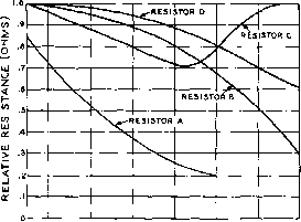 5 10 FREQUENCY (МС! Figure 3 FREQUENCY EFFECTS ON SAMPLE COMPOSITION RESISTORS I О Ll. H 10
RSHUNT -ЛУ>- I S 10 IS FREQUENCY (МСО Figure 4 CURVES OF THE IMPEDANCE OF WIRE-WOUND RESISTORS AT RADIO FREQUENCIES the impedance of the resistor may be thought of as a series reactance (Xg) as shown in figure 2B. This reactance may be either inductive or cacitive depending upon whether the residual inductance or the distributed capacitance of the resistor is the dominating factor. As a rule, skin effect tends to increase the reactance with frequency, while the capacity between turns of a wire-wound resistor, or capacity between the granules of a composition resistor tends to cause the reactance and resistance to drop with frequency. The behavior of various types of composition resistors over a large frequency range is shown in figure 3. By proper component design, non-inductive re-sistcM-s having a minimum of residual reactance characteristics may be constructed. Even these have reactive effects that cannot be ignored at high frequencies. Wirewound resistors act as low-Q inductors at radio frequencies. Figure 4 shows typical curves of the high frequency characteristics of cylindrical wirewound resistors. In addition to resistance variations wirewound resistors exhibit both capacitive and inductive reactance, depending upon the type of resistor and the operating frequency. In fact, such resistors perform in a fashion as low-Q r-f chokes below their parallel self-resonant frequency. 18-2 Capacitors The inherent residual characteristics of capacitors include series resistance, series inductance and shunt resistance, as shown in figure 5- The series resistance and inductance с L RSERIES Figure 5 EQUIVALENT CIRCUIT OF A CAPACITOR depend to a large extent upon the physical configuration of the capacitor and upon the material of which it is made. Of great interest to the amateur constructor is the series inductance of the capacitor. At a certain frequency the series inductive reactance of the capacitor and the c£4acitive reactance are equal and opposite, and the capacitor is in itself series resonant at this frequency. As the operating frequency of the circuit in which the capacitor is used is increased above the series resonant frequency, the effectiveness of the С£фас1гог as a by-passing element deteriorates until the unit is about as effective as a block of wood. By-Pass The usual forms of by-pass ca-Capacitors pacitors have dielectrics of paper, mica, or ceramic. For audio work, and low frequency r-f work up to perhaps 2 Mc. or so, the per capacitors are satisfactory as their relatively high internal inductance has little effect upon the proper operation of the circuit. The actual amount of internal inductance will vary widely with the manufacturing process, and some types of paper capacitors have satisfactory characteristics up to a frequency of 5 Mc. or so. When considering the design of transmitting equipment, it must be remembered that while the transmitter is operating at some relatively low frequency of, say, 7 Mc, there will be harmonic currents flowing through the various by-pass capacitors of the order of 10 ro 20 times the operating frequency. A capacitor that behaves properly at 7 Mc. however, may offer considerable impedance to the flow of these harmonic currents. For minimum harmonic generation and radiation, it is obviously of greatest importance to employ by-pass capacitors having the lowest possible internal inductance. Mica dielectric capacitors have much less internal inductance than do most paper condensers. Figure 6 lists self-resonant frequencies of various mica capacitors having various lead lengths. It can be seen from inspection of this table that most mica capacitors become seif-resonant in the 12-Mc. to 50-Mc. region. The inductive reactance they would offer to harmonic currents of 100 Mc. or so
Figure 6 SELF-RESONANT FREQUENCIES OF VARIOUS CAPACITORS WITH RANDOM LEAD LENGTH would be of considerable magnitude. In certain instances it is possible to deliberately series-resonate a mica capacitor to a certain frequency somewhat below its normal self-resonant frequency by trimming the leads to a critical length. This is sometimes done for maximum by-passing effect in the region of 40 Mc. to 60 Mc. The recently developed button-mica capacitors shown in figure 7 are especially designed to have extremely low internal inductance. Certain types of button-mica capacitors of small physical size have a self-resonant frequency in the region of 600 Mc. Ceramic dielectric capacitors in general have the lowest amount of series inductance per unit of capacitance of these three universally used types of by-pass capacitors. Typical resonant frequencies of various ceramic units are listed in figure 6. Ceramic capacitors are available in various voltage and capacity ratings and different physical configurations. Stand-off types such as shown in figure 7 are useful for by-passing socket and transformer terminals. Two of these capacitors may be mounted in close proximity on a chassis and connected together by an r-f choke to form a highly effective r-f filter. The inexpensive clamshell type of ceramic capacitor is recommended for general by-passing in r-f circuitry, as it is effective as a by-pass unit to well over 100 Mc. The large TV doorknob capacitors are useful as by-pass units for high voltage lines. These capacitors have a value of 500 micromicrofarads, and are available in voltage ratings up to 40,000 volts. The dielectric of these capacitors is usually titanium-dioxide. This material exhibits piezo-electric effects, and capacitors employing it for a dielectric will tend to talk-back when a-c voltages are applied across them. When these capaci- tors are used as plate bypass units in a modulated transmitter they will cause acoustical noise. Otherwise they are excellent for general r-f work. A recent addition to the varied line of capacitors is the coaxial or Hypass type of capacitor. These capacitors exhibit superior by-passing qualities at frequencies up to 200 Mc. and the bulkhead type are especially effective when used to filter leads passing through partition walls between two stages. Variable Air Even though air is the perfect Capacitors dielectric, air capacitors exhibit losses because of the inherent resistance of the metallic parts that make up the capacitor. In addition, the leakage loss across the insulating supports may become of some consequence at high frequencies. Of greater concern is the inductance of the capacitor at high frequencies. Since the capacitor must be of finite size, it will have tie-rods and metallic braces and end plates, all of which contribute to the inductance of the unit. The actual amount of the inductance will depend upon the physical size of the capacitor and the method used to make contact to the stator and rotor plates. This inductance may be cut to a minimum value by using as small a capacitor as is practical, by using insulated tie-rods to prevent the formation of closed inductive loops in the frame of the unit, and by making connections to the centers of the plate assemblies rather than to the ends as is com-    Figure 7 TYPES OF CERAMIC AND MICA CAPACITORS SUITABLE FOR HIGH-FREQUENCY BYPASSING Tbe Centralob BSBS (1000 /t/t/c/) is recom-menc/ec/ for screen onof plote circufts of tef-roJe tubes. monly done. A large transmitting capacitor may have an inherent inductance as large as 0.1 microhenry, making the capacitor susceptible to parasitic resonances in the 50 Mc. to 150 Mc. range of frequencies. The question of optimum C/L ratio and capacitor plate spacing is covered in Chapter Thirteen. For all-band operation of a high power stage, it is recommended that a capacitor just large enough for 40-meter phone operation be chosen. (This will have sufficient capacitance for phone operation on all higher frequency bands.) Then use fixed padding capacitors for operation on 80 meters. Such padding capacitors are available in air, ceramic, and vacuum types. Specially designed variable capacitors are recommended for u-h-f work; ordinary capacitors often have loops in the metal frame which may resonate near the operating frequency. Variable Vacuum Variable vacuum capacitors Capacitors because of their small phy- sical size have less inherent inductance per unit of capacity than do variable air capacitors. Their losses are extremely low, and their dielectric strength is high. Because of increased production the cost of such units is now within the reach of the designer of amateur equipment, and their use is highly recommended in high power tank circuits. 18-3 Wire and Inductors Any length of wire, no matter how short, has a certain value of inductance. This property is of great help in making coils and inductors, but may be of great hindrance when it is not taken into account in circuit design and construction. Connecting circuit elements (themselves having residual inductance) together with a conductor possessing additional inductance can often lead to puzzling difficulties. A piece of no. 10 copper wire ten inches long (a not uncommon length for a plate lead in a transmitter) can have a self-inductance of 0.15 microhenries. This inductance and that of the plate tuning capacitor together with the plate-to-ground capacity of the vacuum tube can form a resonant circuit which may lead to parasitic oscillations in the v-h-f regions. To keep the self-inductance at a minimum, all r-f carrying leads should be as short as possible and should be made out of as heavy material as possible. At the higher frequencies, solid enamelled copper wire is most efficient for r-f leads. Tinned or stranded wire will show greater losses at these frequencies. Tank coil and tank capacitor leads should be of heavier wire than other r-f leads. The best type of flexible lead from the envelope of a tube to a terminal is thin copper strip, cut from thin sheet copper. Heavy, rigid leads to these terminals may crack the envelope glass when a tube heats or cools. Wires carrying only a.f. or d.c. should be chosen with the voltage and current in mind. Some of the low-filament-voitage transmitting tubes draw heavy current, and heavy wire must be used to avoid voltage drop. The voltage is low, andhence not much insulation is required. Filament and heater leads are usually twisted together. An initial check should be made on the filament voltage of all tubes of 25 watts or more plate dissipation rating. This voltage should be measured right at the tube sockets. If it is low, the filament transformer voltage should be raised. If this is impossible, heavier or parallel wires should be used for filament leads, cutting down their length if possible. Coaxial cable may be used for high voltage leads when it is desirable to shield them from r-f fields. RG-8/U cable may be used at d-c potentials up to 8000 volts, and the lighter RG-17/U may be used to potentials of 3000 volts. Spark-plug type high-tension wire may be used for unshielded leads, and will withstand 10,000 volts. If this cable is used, the high-voltage leads may be cabled with filament and other low-voltage leads. For high-voltage leads in low-poT/cr exciters, where the plate voltage is not over 450 volts, ordinary radio hookup wire of good qualiry will serve the purpose. No r-f leads should be cabled; in fact it is better to use enamelled or bare copper wire for r-f leads and rely upon spacing for insulation. All r-f joints should be soldered, and the joint should be a good mechanical junction before solder is applied. The efficiency and Q of air coils commonly used in amateur equipment is a factor of the shape of the coil, the proximity of the coil to other objects (including the coil form) and the material of which the coil is made. Dielectric losses in so-called air wound coils are low and the Q of such coils runs in the neighborhood of 300 to 500 at medium frequencies. Unfortunately, most of the transmitting type plug-in coils on the market designed for link coupling have far too small a pick up link for proper operation at 7 Mc. and 3-5 Mc. The coefficient of coupling of these coils is about 0.5, and additional means must be employed to provide satisfactory coupling at these low frequencies. Additional inductance in series with the pick up link, the whole being reso- 1 ... 32 33 34 35 36 37 38 ... 80 |
||||||||||||||||||||||||||||||||||||||||||||||||||||||||||||||||||||||||||||||||||||||||||||||||||||||||||||||||||||||||||||||||||||||||||||||||||||||||||||||||||||||||||||||||||||||||||||||||||||||||||||||||||||||||||||||||||||||||||||||||||||||||||||||||||||||||||||||||||||||||||||||||||||||||||||||||||||||||||||||||||||||||||||||||||||||||||||||||||||||||||||||||||||||||||||||||||||||||||||||||||||||||||||||||||||||||||||||||||||||||||||||||||||||||||||||||||||||||||||||||||||||||||||||||||||||||||||||||||||||||||||||||||||||||||||||||||||||||||||||||||||||||||||||||||||||
|
© 2026 AutoElektrix.ru
Частичное копирование материалов разрешено при условии активной ссылки |