 |
 |
 |
| Главная Журналы Популярное Audi - почему их так назвали? Как появилась марка Bmw? Откуда появился Lexus? Достижения и устремления Mercedes-Benz Первые модели Chevrolet Электромобиль Nissan Leaf |
Главная » Журналы » Simple coaxial reflectometer 1 ... 33 34 35 36 37 38 39 ... 80 HANDBOOK Ind uctors Rc О- L Rc JTJlTiP-О О-t-ЛV с DISTRIBUTED (B) Rc с L О-iW-1(--о © Figure 8 ELECTRICAL EQUIVALENT OF R-F CHOKE AT VARIOUS FREQUENCIES nated to the operating frequency will often permit satisfactory coupling. Coil Placement For best Q a coil should be in the form of a solenoid with length from one to two times the diameter. For minimum interstage coupling, coils should be made as small physically as is practicable. The coils should then be placed so that adjoining coils are oriented for minimum mutual coupling. To determine if this condition exists, apply the following test: the axis of one of the two coils must lie in the plane formed by the center turn of the other coil. If this condition is not met, there will be appreciable coupling unless the unshielded coils are very small in diameter or are spaced a considerable distance from each other. Insulation On frequencies above 7 Mc, ceramic, polystyrene, or Mycalex insulation is to be recommended. Cold flow must be considered when using polystyrene (Am-phenol 912, etc.). Bakelite has low losses on the lower frequencies but should never be used in the field of high-frequency tank circuits. Lucite (or Plexiglas), which is available in rods, sheets, or tubing, is satisfactory for use at all radio frequencies where the r-f voltages are not especially high. It is very easy to work with ordinary tools and is not expensive. The loss factor depends to a considerable extent upon the amount and kind of plas-ticizer used. The most important thing to keep in mind regarding insulation is that the best insulation is air. If it is necessary to reinforce air-wound coils to keep turns from vibrating or touching, use strips of Lucite or polystyrene cemented in place with Amphenol 912 coil dope. This will result in lower losses than the commonly used celluloid ribs and Duco cement. Radio Frequency Choices R-f chokes may be considered to be special inductances designed to have a high value of impedance over a large range of frequencies. A practical r-f choke has inductance, distributed capacitance, and resistance. At low frequencies, the distributed capacity has little effect and the electrical equivalent circuit of the r-f choke is as shown in figure 8A. As the operating frequency of the choke is raised the effect of the distributed capacity becomes more evident until at some particular frequency the distributed capacity resonates with the inductance of the choke and a parallel resonant circuit is formed. This point is shown in figure 8B. As the frequency of operation is further increased the overall reactance of the choke becomes capacitive, and finally a point of series resonance is reached (figure SC.), This cycle repeats itself as the operating frequency is raised above the series resonant point, the impedance of the choke rapidly becoming lower on each successive cycle. A chart of this action is shown in figure 9. It can be seen that as the r-f choke approaches and leaves a condition of series resonance, the performance of the choke is seriously impaired. The condition of series resonance may easily be found by shorting the terminals of the r-f choke in question with a piece of wire and exploring the windings of the choke with a grid-dip oscillator. Most commercial transmitting type chokes have series resonances in the vicinity of 11 Mc or 24 Mc. 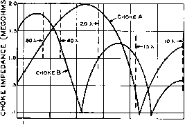 S 10 IS 20 25 FREQUENCY (МС.) Figure 9 FREQUENCY-IMPEDANCE CHARACTERISTICS FOR TYPICAL PIE-WOUND R-F CHOKES о о LOOP 2 j CHASSIS О о о ® 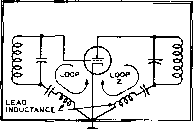 CHA33IS Figure 10 GROUND LOOPS IN AMPLIFIER STAGES A. Using chassis return B. Common grounti point 18-4 Grounds At frequencies of 30 Mc. and below, a chassis may be considered as a fixed ground reference, since its dimensions are only a fraction of a wavelength. As the frequency is increased above 30 Mc, the chassis must be considered as a conducting sheet on which there are points of maximum current and potential. However, for the lower amateur frequencies, an object may be assumed ro be at ground potential when it is affixed to the chassis. In transmitter stages, two important current loops exist. One loop consists of the grid circuit and chassis return, and the other loop consists of the plate circuit and chassis return. These two loops are shown in figure lOA. It can be seen that the chassis forms a return for both the grid and plate circuirs, and that ground currents flow in the chassis towards the cathode circuit of the stage. For some years the theory has been to separate these ground currents from the chassis by returning all ground leads to one point, usually the cathode of the tube for the stage in question. This is well and good if the ground leads are of minute length and do not introduce cross couplings between the leads. Such a technique is illustrated in figure lOB. wherein all srage components are grounded to the cathode pin of the stage socket. However, in transmirter construction the physical size of the components prevent such close grouping. It is necessary to spread the components of such a stage over a fairly large area. In this case it is best to ground items directly ro the chassis at the nearest possible point, with short, direct grounding leads. The ground currents will flow from these points through the low inductance chassis to the cathode return of the stage. Components grounded on the top of the chassis have their ground currents flow through holes to the cathode circuir which is usually located on the bottom of the chassis, since such currents travel on the surface of the chassis. The usual top to bottom ground path is through the hole cut in the chassis for the tube socket. When the gain per stage is relatively low, or there are only a small number of stages on a chassis this universal grounding system is ideal. It is only in high gain stages (i-f strips) where rhe gain per inch is very high that circulating ground currents will cause оретаг1опа1 instability. Intercoupling of It is important to prevent in-Ground Currents tercoupling of various different ground currents when the chassis is used as a common ground return. To keep this intercoupling at a minimum, the stage should be completely shielded. This will prevent external fields from generating spurious ground currents, and prevent the ground currents of the stage from upsetting the action of nearby srages. Since the ground currents travel on the surface of the metal, the stage should be enclosed in an electrically tight box. When rhis is done, all ground currents genered inside rhe box will remain in the box. The only possible means of escape for fundamental and harmonic currents are imperfections in this electrically tight box. Whenever we bring a wire lead into the box, make a ventilation hole, or bring a control shaft through the box we create an imperfecrion. It is important that the effect of these imperfec-rions be reduced to a minimum. 18-5 Holes, Leads and Shafts Large size holes for ventilarion may be put in an electrically tight box provided they are properly screened. Perforated metal stock having many small, closely spaced holes is the best screening material. Copper wire screen may be used provided the screen wires are bonded rogerher every few inches. As the wire corrodes, an insulating film prevents contact between the individual wires, and the attenuation of the screening suffers. The screening material should be carefully soldered to the HANDBOOK Shielding 363 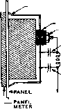 -TIN CAN BOTTOM WITH FLUTED EDSE PRESSED AGAINST PANEL RUBBER GROMMET METER NUT -.001 CERAMIC :rfc vOOl CERAMIC 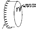 METER FLUTED EDGES TO MAKE GOOD ELECTRICAL CONTACT WITH PANEL COAXIAL SOCKET COAXIAL PLUG LcOAXU EXTERNAL FIELD ELECTRICALLY TIGHT BOX OAXIAL SHIELD -CENTER CONDUCTOR GROUND CURRENTS IN BOX RIGHT Figure ПА SIMPLE METER SHIELD box, or bolted with a spacing of not less than two inches between bolts. Mating surfaces of the box and the screening should be clean. A screened ventilation opening should be roughly three times the size of an equivalent unscreened opening, since the screening represents about a 70 per cent coverage of the area. Careful attention must be paid to equipment heating when an electrically tight box is used. Commercially available panels having half-inch ventilating holes may be used as part of the box. These holes have much less attenuation than does screening, but will perform in a satisfactory manner in all but the areas of weakest TV reception. If it is desired to reduce leakage from these panels to a minimum, the back of the grille must be covered with screening tightly bonded to the panel. Doors may be placed in electrically tight boxes provided there is no r-f leakage around the seams of the door. Electronic weather-stripping or metal finger stock may be used to seal these doors. A long, narrow slot in a closed box has the tendency to act as a slot antenna and harmonic energy may pass more readily through such an opening than it would through a much larger circular hole. Variable capacitor shafts or switch shafts may act as antennas, picking up currents inside the box and re-radiating them outside of the box. It is necessary either to ground the shaft securely as it leaves the box, or else to make the shaft of some insulating material. A two or three inch panel meter requires a large leakage hole if it is mounted in the wall of an electrically tight box. To minimize leakage, the meter leads should be by-passed and shielded. The meter should be encased with a metal shield that makes contact to the box entirely around the meter. The connecting Studs of the meter may project through the back of the metal shield. Such a shield may be made out of the end of a tin can of correct OPEN- BOX TERNAL ELO INTERNAL GROUND CURRENTS WRONG Figure 11B Use of coaxial connectors on elecfricaliy tig/it box prevents escape of ground currents from interior of box. At t/ie same time external fields are not conducted into the interior of the box. diameter, cut to fit the depth of the meter. This complete shield assembly is shown in figure 11 A. Careful attention should be paid to leads entering and leaving the electrically tight box. Harmonic currents generated within the box can easily flow out of the box on power or control leads, or even on the outer shields of coaxially shielded wires. Figure IIB illustrates the correct method of bringing shielded cables into a box where it is desired to preserve the continuity of the shielding. Unshielded leads entering the box must be carefully filtered to prevent fundamental and harmonic energy from escaping down the lead. Combinations of r-f chokes and low inductance by-pass capacitors should be used in power leads. If the current in the lead is high, the chokes must be wound of large gauge wire. Composition resistors may be substituted for the r-f chokes in high impedance circuits. Bulkhead or feed-through type capacitors are preferable when passing a lead through a shield partition. A summary of lead leakage with various filter arrangements is shown in figure 12. Internal Leads Leads that connect two points within an electrically tight box FIELD strength TEST INJUV no. (- 2 3 4 5 7 e 9 ю ii 12 12 000 ioooo 830 800 iso 70 140 600 i 10 so 25 trace small hole in shield osc. I -LCi elded hook-up wire T1 5HIELD I Гл rfc C4 RFC -LC3 3,gaELDEDywiRE Rl- looon carbon rfc-ohmite z-so Cl - 75JUyjF ceramic feed-through C2 -.005 disc ceramic Сз - .01 sprague hi-pass C4 - .005 ceramic feed-through Figure 12 LEAD LEAKAGE WITH VARIOUS LEAD FILTERING SYSTEMS (COURTESY WIDBM) was operated near this frequency marked in-stability was noted, and the filaments of the 810 tubes increased in brilliance when plate voltage was applied to the amplifier, indicating the presence of r.f. in the filament circuir. Changing the filament by-pass capacitors to .01-/xfd. lowered the filament resonance frequency to 2.2 Mc. and cured this effect. A ceramic capacitor of .Ol-jxid. used as a filament by-pass capacitor on each filament leg seems to be satisfactory from both a resonant and a TVI point of view. Filament by-pass capacitors smaller in value than .01-fd. should be used with caution. Various parasitic resonances are also found in plate and grid tank circuits. Push-pull tank circuits are prone to double resonances, as shown in figure 14. The parasitic resonance circuit is usually several megacycles higher than the actual resonant frequency of the full tank circuit. The cure for such a double resonance is the inclusion of an r-f choke in the center tap lead to the split coil. Chassis Moterial From a point of view of electrical properties, aluminum is a poor chassis material. It is difficult to make a soldered joint to it, and all grounds must rely upon a pressure joint. These pres- may pick up fundamental and harmonic currents if they are located in a strong field of flux. Any lead forming a closed loop with itself will pick up such currents, as shown in figure 13. This effect is enhanced if the lead happens to be self-resonant at the frequency at ich the exciting energy is supplied. The solution for all of this is to by-pass all internal power leads and control leads at each end, and to shield these leads their entire length. All filament, bias, and meter leads should be so treated. This will make the job of filtering the leads as they leave the box much easier, since normally cool leads within the box will not have picked up spurious currents from nearby hor leads. Figure 13
® WRONG ILLUSTRATION OF HOW A SUPPOSEDLY GROUNDED POWER LEAD CAN COUPLE ENERGY FROM ONE COMPARTMENT TO ANOTHER 18-6 Parasitic Resonances Filament leads within vacuum tubes may resonate with the filament by-pass capacitors at some particular frequency and cause instability in an amplifier stage. Large tubes of the 810 and 250TH type are prone ro this spurious effect. In particular, a push-pull 810 amplifier using .001-jlifd. filament by-pass capacitors had a filament resonant loop that fell in the 7-Mc. amateur band. When the amplifier ® RIGHT electrically-tight compartment radiation FIELD electrically-tight compartment bulkhead TYPE Y-PASS CAPACITOR PICKUP loop ILLUSTRATION OF LEAD ISOLATION BY PROPER USE OF BULKHEAD BYPASS CAPACITOR  RESONANCE LOOP ESONANCE LOOP  WRONG RIGHT Figure 14 DOUBLE RESONANCE EFFECTS IN PUSH-PULL TANK CIRCUIT MAY BE ELIMINATED BY THE INSERTION OF ANY R-F CHOKE IN THE COIL CENTER TAP LEAD sure joints are prone to give trouble at a later date because of high resistivity caused by the formation of oxides from eletrolytic action in the joint. However, the ease of working and forming the aluminum material far outweighs the electrical shortcomings, and aluminum chassis and shielding may be used with good results provided care is taken in making all grounding connections. Cadmium and zinc plated chassis are preferable from a corrosion standpoint, but are much more difficult to handle in the home workshop. 18-7 Parositlc Osctllotion in R-F Amplifiers Parasitics (as distinguished from self-oscillation on the normal tuned frequency of the amplifier) are undesirable oscillations either of very high or very low frequencies which may occur in radio-frequency Eunplifiers. They may cause spurious signals (which are often rough in tone) other than normal harmonics, hash on each side of a modulated carrier, key clicks, voltage breakdown or flash-over, instability or inefficiency, and shortened life or failure of the tubes. They may be damped and stop by themselves after keying or modulation peaks, or they may be undamped and build up during ordinary unmodulated transmission, continuing if the excitation is removed. They may result from series or parallel resonant circuits of all types. Due to neutralizing lead length and the nature of most parasitic circuits, the amplifier usually is not neutralized for the parasitic frequency. Sometimes the fact that the plate supply is keyed will obscure parasitic oscillations in a final amplifier stage that might be very severe if the plate voltage were left on and the excitation were keyed. In some cases, an all-wave receiver will prove helpful in locating v-h-f spurious oscillations, but it may be necessary to check from several hundred megacycles downward in frequency to the operating range. A normal harmonic is weaker than the fundamental but of good tone; a strong harmonic or a rough note at any frequency generally indicates a parasitic. In general, the cure for parasitic oscillation is two-fold: The oscillatory circuit is damped until sustained oscillation is impossible, or it is detuned until oscillation ceases. An examination of the various types of parasitic oscillations and of the parasitic oscillatory circuits will prove handy in applying the correct cure. Low Frequency One type of unwanted Parositic Oscillations oscillation often occurs in shunt-fed circuits in which the grid and plate chokes resonate, coupled through the tubes interelectrode capacitance. This also can happen with series feed. This oscillation is generally at a much lower frequency than the operating frequency and will cause additional carriers to appear, spaced from perhaps twenty to a few hundred kilocycles on either side of the main wave. Such a circuit is illustrated in figure 15. In this case, RFCj and RFCj form the grid and plate inductances of the parasitic oscillator. The neutralizing capacitor, no longer providing out-of-phase feedback to the grid circuit actually enhances the low frequency oscillation. Because of the low Q of the r-f chokes, they will usually run warm when this type of parasitic oscillation is present and may actually char and burn up. A neon bulb held near the oscillatory circuit will glow a bright yellow, the color appearing near the glass of the neon bulb and not between the electrodes. One cure for this type of oscillation is to change the type of choke in either the plate or the grid circuit. This is a marginal cure, because the amplifier may again break into the same type of oscillation when the plate voltage is raised slightly. The best cure is to remove the grid r-f choke entirely and replace it with a wirewound resistor of sufficient wattage to carry the amplifier grid current. If the inclusion of such a resistor upsets the operating bias of the stage, an r-f choke may be used, with a 100-ohm 2-watt carbon resistor in series with the choke to lower the operating Q of the choke. If this expedient does not eliminate the condition, and the stage under investigation uses a beam-tetrode tube, negative resistance can exist in the screen circuit 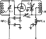 R.F. CIRCUIT  О RFCa 2 PLATE 2 TANK О PARASITIC CIRCUIT FOR LOW FREQ. OSCILLATION О 7Г RFC I о о ® © Figure IS THE CAUSE AND CURE OF LOW FREQUENCY PARASITICS CURE :RFCz of such tubes. Try larger and smaller screen by-pass capacitors to determine whether or not they have any effect. If the condition is coming from the screen circuir an audio choke with a resistor across it in series with the screen feed lead will often eliminate the trouble. Low-frequency parasitic oscillations can often take place in the audio system of an AM transmitter, and their presence will not be known until the transmirter is checked on a receiver. It is easy to determine whether or not the oscillations are coming from the modulator simply by switching off the modulator tubes. If the oscillations are coming from the modulator, the stage in which they are being generated can be determined by removing tubes successively, starting with the first speech amplification stage, until the oscillation stops. When the stage has been found, remedial steps can be taken on that stage. If the stage causing the oscillation is a low-level speech stage it is possible that the trouble is coming from r-f or power-supply feedback, or it may be coming about as a result of inductive coupling between two transformers. If the oscillation is taking place in a high-level audio stage, it is possible that inductive or capacitive coupling is taking place back to one of the low-level speech stages. It is also possible, in certain cases, that parasitic push-pull oscillation can take place in a Class В or Class AB modulator as a result of the grid-to-plate capacitance within the tubes and in the stage wiring. This condition is more likely to occur if capacitors have been placed across the secondary of the driver transformer and across the primary of the modulation transformer to act in the reduction of the amplitude of the higher audio frequencies. Relocation of wiring or actual neutralization of the audio stage in the manner used for r-f stages may be required. It may be said in general that the presence of low-frequency parasitics indicates that somewhere in the oscillating circuit there is an impedance which is high ar a frequency in the upper audio or low r-f range. This impedance may include one or more r-f chokes of the conventional variety, power supply chokes, modulation components, or rhe high impedance may be presented simply by an RC circuit such as might be found in rhe screen-feed circuir of a beam-tetrode amplifier stage. 18-8 Elimination of V-H-F Parasitic Oscillations V-h-f parasitic oscillarions are often difficult to locate and difficult to eliminate since their frequency often is only moderarely above the desired frequency of operation. But it may be said that v-h-f parasitics always may be eliminated if the operating frequency is appreciably below the upper frequency limit for the tubes used in the stage. However, the elimination of a persistent parasitic oscillation on a frequency only moderarely higher than the desired operating frequency will involve a sacrifice in either the power ourput or the power sensitivity of the stage, or in both. Beam-tetrode stages, particularly those using 807 type tubes, will almost invariably have one or more v-h-f parasitic oscillations unless adequate precautions have been taken in advance. Many of the units described in rhe constructional section of this edition had parasitic oscillations when first constructed. But these oscillations were eliminated in each case; hence, rhe expedients used in these equipments should be studied. V-h-f parasitics may be readily identified, as they cause a neon lamp to have a purple glow close to the electrodes when it is excited by the parasitic energy. Parositic Oscillotions Triode stages are less with Triodes subject to parasitic os- cillations primarily because of the much lower power sensitivity of such tubes as compared to beam tetrodes. But such oscillations can and do take place. Usually, however, it is not necessary to incorporate losser resistors as normally is the case with beam tetrodes, unless the triodes are operated quite near to their upper frequency limit, or the tubes are characterized by a relatively high transconductance. Triode v-h-f parasitic oscillations normally may be eliminated by adjustment of the lengths and effective inductance of the leads to the elements of the tubes. In the case of triodes, v-h-f parasitic oscillations often come about as a result of inductance in the neutralizing leads. This is particularly true in the case of push-pull amplifiers. The cure for this effect will usually be found in reducing the length of the neutralizing leads and increasing their diameter. Both the reduction in length and increase in diameter will reduce the inductance of the leads and tend to raise the parasitic oscillation frequency until it is out of the range at which the tubes will oscillate. The use of straightforward circuit design with short leads will assist in forestalling this trouble at the outset. Butterfly-type tank capacitors with the neutralizing capacitors built into the unit (such as the B&W type) are effective in this regard. V-h-f parasitic oscillations may take place as a result of inadequate by-passing or long by-pass leads in the filament, grid-return and plate-return circuits. Such oscillations also can take place when long leads exist between the grids and the grid tuning capacitor or between the plates and the plate tuning capacitor. The grid and plate leads should be kept short, but the leads from the tuning capacitors to the tank coils can be of any reasonable length insofar as parasitic oscillations are concerned. In an amplifier where oscillations have been traced to the grid or plate leads, their elimination can often be effected by making the grid leads much longer than the plate leads or vice versa. Sometimes parasitic oscillations can be eliminated by using iron or nichrome wire for the grid ot plate leads, or for the neutralizing leads. But in any event it will always be found best to make the neutralizing leads as short and of as heavy conductor as is practicable. In cases where it has been found that increased length in the grid leads for an amplifier is required, this increased length can often be wound into the form of a small coil and still 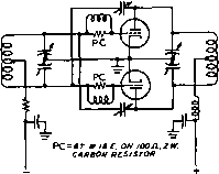 Figure 16 GRID PARASITIC SUPPRESSORS IN PUSH-PULL TRIODE STAGE obtain the desired effect. Winding these small coils of iron or nichrome wire may sometimes be of assistance. To increase losses at the parasitic frequency, the parasitic coils may be wound on 100-ohm 2-watt resistors. These lossy suppressors should be placed in the grid leads of the tubes close to the grid connection, as shown in figure 16. Parasitics with Where beam-tetrode tubes are Beam Tetrodes used in the stage which has been found to be generating the parasitic oscillation, all the foregoing suggesrions apply in general. However, there are certain additional considerations involved in elimination of parasitics from beam-tetrode amplifier stages. These considerations involve the facts that a beam-tetrode amplifier stage has greater power sensitivity than an equivalent triode amplifier, such a stage has a certain amount of screen-lead inductance which may give rise to trouble, and such stages have a small amount of feedback capacitance. Beam-tetrode stages often will require the inclusion of a neutralizing circuit to eliminate oscillation on the operating frequency. However, oscillation on the operating frequency normally is not called a parasitic oscillation, and different measures are required to eliminate the condition. Basically, parasitic oscillations in beam-tetrode amplifier stages fall into two classes: cathode-grid-screen oscillations, and cathode-screen-plate oscillations. Both these types of oscillation can be eliminated through the use of a parasitic suppressor in the lead between the screen terminal of the tube and the screen by-pass suppressor, as shown in figure 17. Such a suppressor has negligible effect on the by-passing effect of the screen at the operating frequency. The method of connecting this 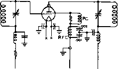 PC=3 7; mieE.OH Ил, г v. CARBON RESISTOR K,= OHMITE Z-SO OR EQUIVALENT Figure 17 SCREEN PARASITIC SUPPRESSION CIRCUIT FOR TETRODE TUBES suppressor to tubes having dual screen leads is shown in figure 18. At the higher frequencies at which parasitics occur, the screen is no longer at ground potential. It is therefore necessary to include an r-f choke by-pass condenser filter in the screen lead after the parasitic suppressor. The screen lead, in addition, should be shielded for best results. During parasitic oscillations, considerable r-f voltage appears on the screen of a retrode tube, and the screen by-pass condenser can easily be damaged. It is best, therefore, to employ screen by-pass condensers whose d-c working voltage is equal to twice the maximum applied screen voltage. The grid-screen oscillations may occasionally be eliminated through the use of a parasitic suppressor in series with the grid lead of the tube. The screen plate oscillations may also be eliminated by inclusion of a parasitic suppressor in series with the plate lead of the tube. A suitable grid suppressor may be made of a 22-ohm 2-watt Ohmite or Allen-Bradley resistor wound with 8 turns of no. 18 enameled wire. A plate circuit suppressor is more of a problem, since it must dissipate a quantity of power that is dependent upon just how close the parasitic frequency is to the operating frequency of the tube. If the two frequencies are close, the suppressor will absorb some of the fundamental plate circuit power. For kilowatt stages operating no higher than 30 Mc. a satisfactory plate circuit suppressor may be made of five 570-ohm 2-watt carbon resistors in parallel, shunted by 5 turns of no. 16 enameled wire, Va inch diameter and Уг inch long (figure 19A and B). The parasitic suppressor for the plate circuit of a small tube such as the 5763, 2E26, 807, 6146 or similar rype normally may consist of a 47-ohm carbon resistor of 2-watt size with 6 turns of no. 18 enameled wire wound around the resistor. However, for operation above 30 Mc, special tailoring of the value 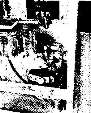 Figure 18 PHOTO OF APPLICATION OF SCREEN PARASITIC SUPPRESSION CIRCUIT OF FIGURE 17 of the resistor and the size of the coil wound around it will be required in order to attain satisfactory parasitic suppression without excessive powerless in the parasitic suppressor. Tetrode Screening Isolation between the grid and plate circuits of a tetrode tube is not perfect. For maximum stability, it is recommended that the tetrode stage be neutralized. Neutralization is absolutely necessary unless the grid and plate circuits of the tetrode stage are each completely isolated from each other in electrically tight boxes. Even when this is done, the stage will show signs of regeneration when the plate and grid tank circuits are tuned to the same frequency. Neutralization will eliminate this regeneration. Any of the neutralization circuits described in the chapter Generation of RF Energy may be used. ]8-9 Checking for-Parasitic Oscillations It is an unusual transmitter which harbors no parasitic oscillations when first constructed PC = aT.m-iae.om глл.гж composition Rssisrop 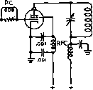 ® с ® FOR e0 7, ETC. PC = er # 1в£. on 4ТЛ, г т. composition resisto/t FOR 4-250A, ETC. PC.-s-s?oa, гш composition resistors in parallel witn sTttiae. U4 oiA. Figure 19 PLATE AND GRID PARASITIC SUPPRESSION IN TETRODE TUBES and tested. Therefore it is always wise to follow a definite procedure in checking a new transmitter for parasitic oscillations. Parasitic oscillations of all types are most easily found when the stage in question is running by itself, with full plate (and screen) voltage, sufficient prorective bias to limit the plate current to a safe value, and no excitation. One stage should be tested at a time, and the complete transmitter should never be put on the air until all stages have been thoroughly checked for parasitics. To protect tetrode tubes during tests for parasitics, the screen voltage should be applied through a series resistor which will limit the screen current to a safe value in case the plate voltage of the tetrode is suddenly removed when the screen supply is on. The coi-rect procedure for parasitic testing is as follows (figure 20): 1. The stage in question should be coupled to a dummy load, and tuned up in correct operating shape. Sufficient protective bias should be applied to the tube at all times. For protection of the stage under test, a lamp bulb should be added in series with one leg of the primary circuit of the high voltage power supply. As the plate supply load increases during a period of parasitic oscillation, the voltage drop across the lamp increases, and the effective plate voltage drops. Bulbs of various size may be tried to adjust the voltage under testing conditions to the correct amount. If a Variac or Powerstat is at hand, it may be used in place of the bulbs for smoother voltage control. Dont test for parasitics unless some type of voltage control is used on the high voltage supply! When a stage breaks into parasitic oscillations, the plate current increases violently, and some protection to the tube under test must be used. 2. The r-f excitation to the tube should now be removed. When this is done, the grid, screen and plate currents of the tube should drop to zero. Grid and plate tuning condensers should be tuned to minimum capacity. No change in resting grid, screen or plate current should be observed. If a parasitic is present, grid current will flow, and there will be an abrupt increase in plate current. The size of the lamp bulb in series with the high voltage supply may be varied until the stage can oscillate continuously, without exceeding the rated plate dissipation of the tube. 3. The frequency of the parasitic may now be determined by means of an absoфtion wave meter, or a neon bulb. Low frequency oscillations will cause a neon bulb to glow yellow. High frequency oscillations will cause the bulb to have a soft, violet glow. Once the frequency of oscillation is determined, rhe cures suggested in this chapter may be applied to the stage, 4. When the stage can pass the above test with no signs of parasitics, the bias supply of the tube in question should be decreased until the tube is dissipating its full plate rating when full plate voltage is plied, with no r-f ЕХСРТЕЙ AMPLIFIERSTAGE TO BE TESTED FOR PARASITICS EXCITER CONTROL SWITCH DJMMY LOAD
A.c. SUPPLY Figure 20 SUGGESTED TEST SETUP FOR PARASITIC TESTS excitation. Excitation may now be applied and the stage loaded to full input into a dummy load. The signal should now be monitored in a nearby receiver which has the antenna terminals grounded or otherwise shorted out. A series of rapid dots should be sent, and the frequency spectrum for several megacycles each side of the carrier frequency carefully searched. If any vestige of parasitic is left, it will show up as an occasional pop on a keyed dot. This pop may be enhanced by a slight detuning of either the grid or plate circuit. 5. If such a parasitic shows up, it means that the stage is still not stable, and further measures must be applied to the circuit. Parasitic suppressors maybe needed in both screen and grid leads of a tetrode, or perhaps in both grid and neutralizing leads of a triode stage. As a last resort, a 10,000-ohm 25-watt wire-wound resistor may be shunted across the grid coil, or grid tuning condenser of a high powered stage. This strategy removed a keying pop that showed up in a commercial transmitter, operating at a plate voltage of 5000. Test for Parasitic It is common experience Tendency in Tetrode to develop an engineer-Amplifiers ing model of a new equipment that is apparently free of parasitics and then find troublesome oscillations showing up in production units. The reason for this is that the equipment has a parasitic tendency that remains below the verge of oscillation until some change in a component, tube gain, or operating condition raises the gain of the parasitic circuit enough to start oscillation. In most high frequency transmitters there are a great many resonances in the tank circuits at frequencies other than the desired 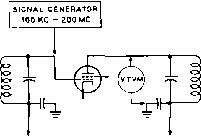 Figure 27 PARASITIC GAIN MEASUREMENT Grid-dip oscillator and vacuum tube voltmeter may be used to measure parasitic stage gain over 100kc-200mc region. operating frequency. Most of these parasitic resonant circuits are not coupled to the tube and have no significant tendency to oscillate. A few, however, are coupled to the tube in some form of oscillatory circuit. If the regeneration is great enough, oscillation at the parasitic frequency results. Those spurious circuits existing just below oscillation must be found and suppressed to a safe level. One test method is to feed a signal from a grid-dip oscillator into the grid of a stage and measure the resulting signal level in the plate circuit of the stage, as shown in figure 21. The test is made with all operating voltages applied to the tubes. Class С stages should have bias reduced so a reasonable amount of static plate current flows. The grid-dip oscillator is tuned over the range of 100 kc to 200 mc. and the relative level of the r-f voltmeter is watched and the frequencies at which voltage peaks occur are noted. Each significant peak in voltage gain in the stage must be investigated. Circuit changes or suppression must then be added to reduce all peaks by 10 db or more in amplitude. 1 ... 33 34 35 36 37 38 39 ... 80 |
|||||||||||||||||||||||||||||||||||||||||||||||||||
|
© 2026 AutoElektrix.ru
Частичное копирование материалов разрешено при условии активной ссылки |