 |
 |
 |
| Главная Журналы Популярное Audi - почему их так назвали? Как появилась марка Bmw? Откуда появился Lexus? Достижения и устремления Mercedes-Benz Первые модели Chevrolet Электромобиль Nissan Leaf |
Главная » Журналы » Simple coaxial reflectometer 1 ... 34 35 36 37 38 39 40 ... 80 Television and Broadcast Interference The problem of interference to television reception is best approached by the philosophy discussed in Chapter Eighteen. By correct design procedure, spurious harmonic generation in low frequency transmitters may be held to a minimum. The remaining problem is twofold: to make sure that the residual harmonics generated by the transmitter are not radiated, and to make sure that the fundamental signal of the transmitter does not overload the television receiver by reason of the proximity of one to the other. In an area of high TV-signal field intensity the TVI problem is capable of complete solution with routine measures both at the amateur transmitter and at the affected receivers. But in fringe areas of low TV-signal field strength the complete elimination of TVI is a difficult and challenging problem. The fundamentals illustrated in Chapter Fifteen must be closely followed, and additional antenna filtering of the transmitter is required. 19-1 Types of Television Interference There are three main types of TVI which may be caused singly or in combination by the emissions from an amateur transmitter. These types of interference are: (1) Overloading of the TV set by the transmitter fundamental (2) Impairment of the picture by spurious emissions (3) Impairment of the picture by the radiation of harmonics TV Set Even if the amateur transmitter Overloading were perfect and had no harmonic radiation or spurious emissions whatever, it still would be likely to cause overloading of TV sets whose antennas were within a few hundred feet of the transmitting antenna. This type of overloading is essentially the same as the common type of BCI encountered when operating a medium-power ot high-power amateur transmitter within a few hundred feet of the normal type of BCL receiver. The field intensity in the immediate vicinity of the transmitting antenna is sufficiently high that the amateur signal will get into the ВС or TV set either through overloading of the front end, or through the i-f, video, or audio system. A characteristic of this type of interference is that it always will be eliminated when the transmitter temporarily is operated into a dummy antenna. Another characteristic of this type of overloading is that its effects will be substantially continuous over the entire frequency coverage of the ВС or TV receiver. Channels 2 through 13 will be affected in approximately the same manner. With the overloading type of interference the problem is simply to keep the fundamental of the transmitter out of the affected receiver. Other types of interference may or may not show up when the fundamental is taken out of the TV set (they probably will appear), but at least the fundamental must be eliminated first. The elimination of the transmitter fundamental from the TV set is normally the only operation performed on or in the vicinity of the TV receiver. After the fundamental has been elimi- 300-ohm line from <; antenna 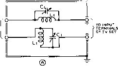 shield box 300 ohm line from antenna 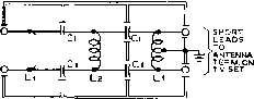 @ FOR300-OHW LINE, SHIELDED OR UNSHIELDED to tv antenna 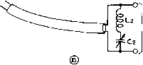 to antenna > terminals of tv set COAX lijf- fitting!! о l3§ о о о (в) FOR 50-75 OHM COAXIAL LINE icoax fitting Figure 1 TUNED TRAPS FOR THE TRANSMITTER FUNDAMENTAL The arrangement at (A) has proven to be effective in eliminating the condition of general blocking as caused by a 28-Mc. transmitter in the vicinity of a TV receiver. The tuned circuits L/-C/ ore resonated separately to the frequency of transmission. The adjustment may be done at the station, or it may be accomplished at the TV receiver by tuning for minimum interference on the TV screen. Shown at (B) is an alternative arrangement with a series-tuned circuit across the antenna terminals af the TV set. The tuned circuit should be resonated to the operating frequency of the transmitter. This arrangement gives less attenuation of the interfering signal than that at (A); the circuit has proven effective with interference from transmitters on the 50-Mc. band, and with low-power 28-Mc. transmitters. Figure 2 HIGH-PASS TRANSMISSION LINE FILTERS The arrangement at (A) will stop the passing of all signals below about 45 Mc. from the antenna transmission line into the TV set. Coils Li are each 1.2 microhenrys (17 turns no. 24 enam. closewound on a-inch dia. polystyrene rod) with the center tap grounded. It will be found best to scrape, twist, and solder the center tap before winding the coil. The number af turns each side of the tap may then be varied until the tap is in the exact center of the winding. Coil L2 is 0.6 microhenry (12 turns no. 24 enam. closewound on a-inch dia. polystyrene rod). The capacitors should be about 16.5 IMd., but either 15 or 20 mitd. ceramic capacitors will give satisfactory results, A similar filter for coaxial antenna transmission line is shown ot (B). Both coils should be 0. 12 microhenry (7 turns no. 18 enam, spaced to V2 inch on й-incfi dia, polystyrene rod). Capacitors C2 should be 75 rtLiW. midget ceramics, while C3 should be a 40-fjpfd. ceramic. nated as a source of interference to reception, work may then be begun on or in the vicinity of the transmitter toward eliminating the other two types of interference. Taking Out the Fundomentol More or less standard BCI-type practice is most commonly used in taking out fundamental interference. Wavetraps and filters are installed, and the antenna system may or may not be modified so as to offer less response to the signal from the amateur transmitter. In regard to a comparison between wavetraps and filters, the same considerations apply as have been effective in regard to BCI for many years; wavetraps are quite effective when properly installed and adjusted, but they must be readjusted whenever the band of operation is changed, or even when moving from one extreme end of a band to the other. Hence, wavetraps are not recommended except when operation will be confined to a relatively narrow portion of one amateur band. However, figure 1 shows two of the most common signal trapping arrangements. High-Pass Filters High-pass filters in the antenna lead of the TV set have proven to be quite satisfactory as a means of eliminating TVI of the overloading type. In many cases when the interfering transmitter is operated only on the bands below 7.3 Mc, the use of a high-pass filter in the antenna lead has completely eliminated all TVI. In some cases the installation of a high-pass filter in the antenna transmission line and an a-c line filter of a standard variety has proven to be completely effective in eliminating the interference from a transmitter operating in one of the lower frequency amateur bands. In general, it is suggested that commercially manufactured high-pass filters be purchased. Such units are available from a number of manufacturers at a relatively moderate cost. However, such units may be home constructed; suggested designs are given in figures 2 and 3. Types for use both with coaxial and with balanced transmission lines have been shown. In most cases the filters may be constructed in one of the small shield boxes which are now on the market. Input and output terminals may be standard connectors, or the inexpensive type of terminal strips usually used on ВС and TV sets may be employed. Coaxial terminals should of course be employed when a coaxial feed line is used to the antenna. In any event the leads from the filter box to the TV set should be very short, including both the antenna lead and the ground lead to the box itself. If the leads from the box to the set have much length, they may pick up enough signal to nullify the effects of the high-pass filter. Blocking from Operation on the 50-Mc. ama-50-Mc. Signals teur band in an area where channel 2 is in use for TV imposes a special problem in the matter of blocking. The input circuits of most TV sets are sufficiently broad so that an amateur signal on the 50-Mc. band will ride through with little attenuation. Also, the normal TV antenna will have a quite large response to a signal in the 50-Mc. band since the lower limit of channel 2 is 54 Mc. High-pass filters of the normal type simply are not capable of giving sufficient attenuation to a signal whose frequency is so close to the necessary pass bandof the filter. Hence, a resonant circuit element, as illustrated in figure 1, must be used to trap out the amateur field at the input of the TV set. The trap must be tuned or the section of transmission line cut, if a section of line is to be used for a particular frequency in the 50-Mc. band. This frequency will have to be near the lower frequency limit of the 50-Mc. band to obtain adequate rejection of the amateur signal while still not materially affecting the response of the receiver to channel 2. Elimination of Spurious Emissions All spurious emissions from amateur transmitters (ignoring harmonic signals for the time being) must be eliminated to com- о  §L3 О Figure 3 SERIES-DERIVED HIGH-PASS FILTER This filter Is designed for use in the 300-ohm transmission line from the TV antenna to the TV receiver. Nominal cutoff frequency is 36 Mc. and maximum rejection is at about 29 Mc, Cj.Ce-5-Щ^<i, zero-coefficfent ceramic С2.Сз,С4,С5-20-/ijUfd. lero-eoefficient cero-mic Li.Lb-2-0 Mh. About 24 turns no. 28 d.c.c. wound to % on % diameter polystyrene rod. Turns sliould be adjusted until the coil resonates to 29 Mc. with the associated 1S-AlfUfd. capacitor. -0.66 Mh., 14 turns no. 28 d.c.c. wound to on % dia. polystyrene rod. Adjust turns to resonate externally to 20 Mc. with an auxiliary 100-/jifd. capacitor whose value is accurately known. ply with FCC regulations. But in the past many amateur transmitters have emitted spurious signals as a result of key clicks, parasitics, and overmodulation transients. In most cases the operators of the transmitters were not aware of these emissions since they were radiated only for a short distance and hence were not brought to his attention. But with one or more TV sets in the neighborhood it is probable that such spurious signals will be brought quickly to his attention. 19-2 Harmonic Radiation After any condition of blocking at the TV receiver has been eliminated, and when the transmitter is completely free of transients and parasitic oscillations, it is probable that TVI will be eliminated in certain cases. Certainly general interference should be eliminated, particularly if the transmitter is a well designed affair operated on one of the lower frequency bands, and the station is in a high-signal TV area. But when the transmitter is to be operated on one of the higher frequency bands, and particularly in a marginal TV area, the job of TVI-proofing will just have begun. The elimination of harmonic radiation from the transmitter is a difficult and tedious job which must be done in an orderly manner if completely satisfactory results are to be obtained.
Figure 4 HARMONICS OF THE AMATEUR BANDS Showrj are the harmonic frequency ranges of the amateur bands between 7 and 54 Mc, with the TV channels (and TV i-f systems) which are most likely to receive interference from these harmonics. Under certain conditions amateur signals in the 1.8 and 3.5 Mc. bands can cause interference as a result of direct pickup in the video systems of TV receivers which are not adequately shielded. First it is well to become familiar with the TV channels presently assigned, with the TV intermediate frequencies commonly used, and with the channels which will receive interference from harmonics of the various amateur bands. Figures 4 and 5 give this information. Even a short inspection of figures 4 and 5 will make obvious the seriousness of the interference which can be caused by harmonics of amateur signals in the higher frequency bands. With any sort of reasonable precautions in the design and shielding of the transmitter it is not likely that harmonics higher than the 6th will be encountered. Hence the main offenders in the way of harmonic interference will be those bands above 14-Mc. Nature of Harmonic Interference Investigations into the nature of the interference caused by amateur signals on the TV screen, assuming that blocking has been eliminated as described earlier in this chapter, have revealed the following facts: 1. An unmodulated carrier, such as a c-w signal with the key down or an AM signal without modulation, will give a cross-hatch or herringbone pattern on the TV screen. This same general type of picture also will occur in the case of a narrow-band FM signal either with or without modulation. 2. A relatively strong AM signal will give in addition to the herringbone a very serious succession of light and dark bands across the TV picture. 3. A moderate strength c-w signal without transients, in the absence of overloading of the TV set, will result merely in the turning on and off of the herringbone on the picture. To discuss condition (1) above, the herringbone is a result of the beat note between the TV video carrier and the amateur harmonic. Hence the higher the beat note the less obvious will be the resulting cross-hatch. Further, it has been shown that a much stronger signal is required to produce a discernible herringbone when the interfering harmonic is as far away as possible from the video carrier, without running into the sound carrier. Thus, as a last resort, or to eliminate the last vestige of interference after all corrective measures have been taken, operate the transmitter on a frequency such that the interfer- VIDEO 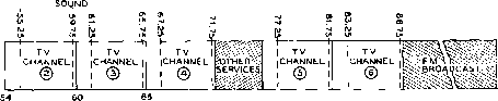 72 76 LOW BAND VIDEO SOUND I TV I [CHANNEL (7 ---\- TV I CHANNEL I ® I I I TV i (CHANNEL I I @ i I TV 1 CHANNEL I @ i I i ® i TV .CHANNEL I ® TV I CHANNEL i I TV ICHANNEL 192 198 HIGH BAND Figure 5 FREQUENCIES OF THE V-H-F TV CHANNELS Showing fhe frequency ranges of TV channels 2 through 13, with the picture carrier and sound carrier frequencies also shown. ing harmonic will fall as far as possible from the picture carrier. The worst possible interference to the pictiu-e from a continuous carrier will be obtained when the interfering signal is very close in frequency to the video carrier. Isolating Throughout the testing proce- the Source of dure it will be necessary to the Interference have some sott of indicating device as a means of determining harmonic field intensities. The best indicator for field intensities some distance from the transmitting antenna will probably be the TV receiver of some neighbor with whom friendly relations are still maintained. This person will then be able to give a check, occasionally, on the relative nature of the interference.-But it will probably be necessary to go and check yourself periodically the results obtained, since the neighbor probably will not be able to give any sort of a quantitative analysis of the progress which has been made. An additional device for checking relatively high field intensities in the vicinity of the transmitter will be almost a necessity. A simple crystal diode wavemeter, shown in figure 6 will accomplish this function. Also, it will be very helpful to have a receiver, with an S meter, capable of covering at least the 50 to 100 Mc. range and preferably the range to 216 Mc. This device may consist merely of the station receiver and a simple converter using the two halves of a 6J6 as oscillator and mixer. The first check can best be made with the neighbor who is receiving the most serious or the most general interference. Turn on the transmitter and check all channels to determine the extent of the interference and the number of channels affected. Then disconnect the antenna and substitute a group of 100-watt lamps as a dummy load for the transmitter. Experience has shown that 8 100-watt lamps connected in two seriesed groups of four in parallel will take the output of a kilowatt transmitter on 28 Mc. if connections are made symmetrically to the group of lamps. Then note the interference. Now remove plate voltage from the final amplifier and determine the extent of interference caused by the exciter stages. In the average case, when the final amplifier is a beam tetrode stage and the exciter is 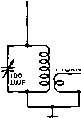 10- PICKUP WIRE ,5Т. 1вЁ. 0.4DIA.,0.5LONG 1N34 coveRAse-ii-i40 mc. .001 ) 0-1 Figure 6 Crystai-diode wavemeter suitable for checking high-intensity harmonics in TV region. relatively low powered and adequately shielded, it will be found that the interference drops materially when the antenna is removed and a dummy load substituted. It will also be found in such an average case that the interference will stop when the exciter only is operating. Tronsmitter It should be made clear at this Power Level point that the level of power used at the transmitter is not of great significance in the basic harmonic reduction problem. The difference in power level between a 20-watt transmitter and one rated at a kilowatt is only a matter of about 17 db. Yet the degree of harmonic attenuation required to eliminate interference caused by harmonic radiation is from 80 to 120 db, depending upon the TV signal strength in the vicinity. This is not to say that it is not a simpler job to eliminate harmonic interference from a low-power transmitter than from a kilo-wact equipment. It is simpler to suppress harmonic radiation from a low-power transmitter simply because it is a much easier problem to shield a low-power unit, and the filters for the leads which enter the transmitter enclosure may be constructed less expensively and smaller for a low-power unit. 19-3 Low-Pass Filters After the transmitter has been shielded, and all power leads have been filtered in such a manner that the transmitter shielding has not been rendered ineffective, the only remaining available exit for harmonic energy lies in the antenna transmission line. Hence the main burden of harmonic attenuation will fall on the low-pass filter installed between the output of the transmitter and the antenna system. Experience has shown that the low-pass filter can best be installed externally to the main transmitter enclosure, and that the transmission line from the transmitter to the low-pass filter should be of the coaxial type. Hence the majority of low-pass filters are designed for a characteristic impedance of 52 ohms, so that RG-8/U cable (or RG-58/U for a small transmitter) may be used between the output of the transmitter and the antenna transmission line or the antenna tuner. Transmitting-type low-pass filters for amateur use usually are designed in such a manner as to pass frequencies up to about 30 Mc. without attenuation. The nominal cutoff frequency of the filters is usually between 38 and 45 Mc, and ra-derived sections with maximum attenuation in chaimel 2 usually are included. Well-designed filters capable of carrying any power level up to one kilowatt are  ® 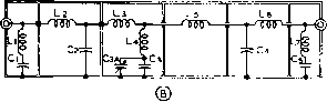 Figure 7 LOW-PASS FILTER SCHEMATIC DIAGRAMS The filter illustrated at (A) uses m-derived terminatirtg half sections at each end, with three constant-k mid-sections. The filter at (B) is essentially the same except that the center section has been changed to act as an m-derived section which can be designed to offer maximum attenuation to channels 2, 4, 5, ar 6 in accordance with the constants given below. Cutoff frequency is 45 Mc. in all cases. All coils, except L4 in (B) above, are wound V2 i,d, with 8 turns per inch. The (A) Filter q,C5-41.5jufcl. (40 IJ.flfd. win be found suitable.) Cj.Cj, 04-136 MMW. (ПО to 140 /xfd. moy be used.) Li.Le-0-2 Ah; 3W t. no. 14 Lj.Ls-0.3 Mh; 5 t. no. 12 l3, l4.-0.37 Mh; 6)4 t. no. 12 The (B) Filter with Mid-Section tuned to Channel 2 (58 Me..) Ci,Cs .41.5 Mfd. Cj, c4-136 IM/Mid, C3-87 MMfd. (50 fj.fj.fd. fixed and 75 fJ.fJ.fd. variable in parallel.) Ll, L,-0.2Mh; 3t. no. 14 Lj, Lj, L5, Lb-0.3 fJ-h; 5 t. no. 12 L4-0.09 fJ.h; 2 t. no. 14 W dia. by Vt long The (B) Filter with Mid-Section tuned to Channel 4 (71 Me.). All components same except thot; C5-106 M/xfd. Lj.Ls-0.33 aah; 6 t. no. 12 l4--O.O5 fJ.h; IK t. no. \4, 38 dia. by 3/8 long. The (B) Filter with Mid-Section tuned to Channel 5 (81 Mc). Change the following: C3-113 fifj.(d. Lj, l5-0.34 Mh; 6 t. no. 12 L -0.033 fJ.h: 1 t. no. 14 3/8 dia. The (B) Filter with Mid-Section tuned to Channel 6 (86 Me.). All components are essentially the same except that the theoretlcol value of l4 Is changed to 0.03 fLh and the capacitance of с3 Is changed to 117 fJ-fifd, HANDBOOK Low Pass Fitters 377 available commercially from several manufacturers. Alternatively, filters in kit form are available from several manufacturers at a somewhat lower price. Effective filters may be home constructed, if the test equipment is available and if sufficient care is taken in the construction of the assembly. Construction of Figures 7, 8 and 9 illustrate Low-Pass Filters high-performance low-pass filters which are suitable for home construction. All are constructed in slip-cover aluminum boxes (ICA no. 29110) with dimensions of 17 by 3 Ъу 2% inches. Five aluminum baffle plates have been installed in the chassis to make six shielded sections within the enclosure. Feed-through bushings between the shielded sections are Johnson no. 135-55. Both the (A) and (B) filter types are designed for a nominal cut-off frequency of 45 Mc, with a frequency of maximum rejection at about 57 Mc. as established by the terminating half-sections at each end. Characteristic impedance is 52 ohms in all cases. The alternative filter designs diagrammed in figure 7B have provision for an additional rejection trap in the center of the filter unit which may be designed to offer maximum rejection in channel 2, 4, 5, or 6, depending upon which channel is likely to be received in the area in question. The only components which must be changed when changing the frequency of the maximum rejection notch in the center of the filter unit are inductors L3, L4, and L5, and capacitor C3. A trimmer capacitor has been included as a portion of C, so that the frequency of maximum rejection can be tuned accurately to the desired value. Reference to figures 5 and 6 will show the amateur bands which are  Figure 8 PHOTOGRAPH OF THE (B) FILTER WITH THE COVER IN PLACE most likely to cause interference to specific TV channels. Either high-power or low-power components maybe used in the filters diagrammed in figure 7. With the small Centralab TCZ zero-coefficient ceramic capacitors used in the filter units of figure 7A or figure 7B, power levels up to 200 watts output may be used without danger of damage to the capacitors, provided the filter is feeding a 52-ohm resistive load. It may be practicable to use higher levels of power with this type of ceramic capacitor in the filter, but at a power level of 200 watts on the 28-Mc. band the capacitors run just perceptibly warm to the touch. As a point of interest, it is the current rating which is of significance to the capacitors used in filters such as illustrated. Since current ratings for small capacitors such as these are not readily available, it is not possible to establish an accurate power rating for such a unit. The high-power unit illustrated in figure 9, which uses Ceotralab type 850S and 854S capacitors, 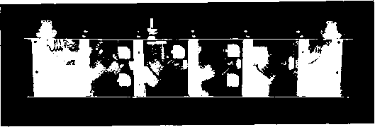 Figure 9 PHOTOGRAPH OF THE (B) FILTER WITH COVER REMOVED The midsection in this filter is adjusted for maximum rejection of channel 4. Note that the main coils of the filter are mounted at an angle of about 45 degrees so that there will be minimum inductive coupling from one section to the next through the holes in the aluminum partitions. Mounting tbe coils in this manner was found to give a measurable improvement in the attenuation characteristics of the filter. has proven quite suitable for power levels up to one kilowatt. Capacitors Ci, Cj, C4, and C, can be standard manufactured units with normal 5 per cent tolerance. The coils for the end sections can be wound to the dimensions given (Lj, Lj, and L,). Then the resonant frequency of the series resonant end sections should be checked with a grid-dip meter, after the adjacent input or output terminal has been shorted with a very short lead. The coils should be squeezed or spread until resonance occurs at 57 Mc. The intermediate ra-derived section in the filter of figure 7B may also be checked with a grid-dip meter for resonance at the correct rejection frequency, after the hot end of L4 has been temporarily grounded with a low-inductance lead. The variable capacitor portion of C3 can be tuned until resonance at the correct frequency has been obtained. Note that there is so little difference between the constants of this intermediate section for channels 5 and 6 that variation in the setting of C3 will tune to either channel without materially changing the operation of the filter. The coils in the intermediate sections of the filter (Lj, L3, L4, and L5 in figure 7A, and Lj, L3, L5, and Lj in figure 7B) may be checked most conveniently outside the filter unit with the aid of a small ceramic capacitor of known value and a grid-dip meter. The ceramic capacitor is paralleled across the small coil with the shortest possible leads. Then the assembly is placed atop a cardboard box and the resonant frequency checked with a grid-dip meter. a Shure reactance slide rule may be used to ascertain the correct resonant frequency for the desired L-C combination and the coil altered until the desired resonant frequency is attained. The coil may then be installed in the filter unit, making sure that it is not squeezed or compressed as it is being installed. However, if the coils are wound exactly as given under figure 10, the filter may be assembled with reasonable assurance that it will operate as designed. Using Low-Pass The low-pass filter con-Filters nected in the output transmission line of the transmitter is capable of affording an enormous degree of harmonic attenuation. However, the filter must be operated in the correct manner or the results obtained will not be up to expectations. In the first place, all direct radiation from the transmitter and its control and power leads must be suppressed. This subject has been discussed in the previous section. Secondly, the filter must be operated into a load impedance approximately equal to its design characteristic impedance. The filter itself will cT Тез Figure 10 SCHEMATIC OF THE SINGLE-SECTION HALF-WAVE FILTER The constants given be/ow are for a characteristic impedance af 52 ohms, for use with RG-8/U and RG-58/U cable. Coil Li should be checked for resonance at the operating frequency with Cj, and the same with L2 and C4. This check can be made by soldering a low-inductance grounding strap to the lead between Lj and L2 where it passes through the shield. When the coils have been trimmed to resonance with a grid-dip meter, the grounding strap should of course be removed This filter type will give an attenuation of about 30 db to the second harmonic, about 48 db to the third, about 60 db to the fourth, 67 to the fifth, and so on increasing at a rate of about 30 db per octave. Ci,C],C3,c4-Silver mica or small ceramic far low power, transmitting type ceramic for high power. Capacitance for different bands is given below: 160 meters-1700 Mifd. 80 meters-850 nufd. 40 meters-440 fififd. 20 meters-220 llflfd. 10 meters-110 flfd. 6 meters-60 fflfd. Li.Lj-May be made up of sections of B&W Mlni-ductor for power levels below 250 wotts, or of no. 12 enam. for power up to one kilowatt. Approximate dimensions for the coils are given below, but the coils should be trimmed to resonate at the proper frequency with a grid-dip meter as discussed above. All coils except the ones for 160 meters are wound 8 turns per inch. 160 meters-4.2 Mh; 22 turns no. 16 enam., 1 dia. 2 long 80 meters-2.1 /xh; 13 t. 1 dia. (No. 3014 Mini- ductor or no. 12) 40 meters-1.1 flh; 8 t. 1 dia. (No. 3014 or no. 12 at 8 t.p.i.) 20 meters-0.55 /Mh; 7 t.*M dia. (No. 3010 or no. 12 at 8 t.p.l.) 10 meters-0.3 6 t. Й dia. (No. 3002 or no. 12 at 8 t.p.i.) 6 meters-0.17 fJ-h; 4 t. Vt dia. (No. 3002 or no. 12 at 8 t.p.i.) have very low losses (usually less than 0.5 db) when operated into its nominal value of resistive load. But if the filter is mis-terminated its losses will become excessive, and it will not present the correct value of load impedance to the transmitter. If a filter, being fed from a high-power transmitter, is operated into an incorrect termination it may be damaged; the coils may be overheated and the capacitors destroyed as a result of excessive r-f currents. Hence it is wise, when first installing a low-pass filter. Figure 11 HALF-WAVE FILTER FOR THE 28.MC. BAND Showing one possible type of construction of a 52-ohm half-wave filter for relative-ly low power operation on the 28-Mc. band. 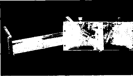 to check the standing-wave ratio of the load being presented to the output of the filter with a standing-wave meter of any of the conventional types. Then the antenna termination or the antenna coupled should be adjusted, with low power on the transmitter, until the s.w.r. of the load being presented to the filter is less than 2.0, and preferably below 1.5. Half-Wave Filters Half-wave filters ( Har-monikets ) have been discussed in various publications including the Nov.-Dec. 1949 GE Ham News. Such filters are relatively simple and offer the advantage that they present the same value of impedance at their input terminals as appears as load across their output terminals. Such fHters normally are used as one-band affairs, and they offer high attenuation only to the third and higher harmonics. Design data on the half-wave filter is given in figure 10. Construction of half-wave filters is illustrated in figure 11. 19-4 Broadcast Interference Interference to the reception of signals in the broadcast band (540 to 1600 kc.) or in the FM broadcast band (88 to 108 Mc.) by amateur transmissions is a serious matter to those amateurs living in densely populated areas. Although broadcast interference has recently been overshadowed by the seriousness of television interference, the condition of BCI is still present. In general, signals from a transmitter operating properly are not picked up by receivers tuned to other frequencies unless the receiver is of inferior design, or is in poor condition. Therefore, if the receiver is of good design and is in good repair, the burden of rectifying the trouble rests with the owner of the interfering station. Phone and c-w stations both are capable of causing broadcast interference, key-click annoyance from the code transmitters being particularly objectionable. A knowledge of each of the several types of broadcast interference, their cause, and methods of eliminating them is necessary for the successful disposition of this trouble. An effective method of combating one variety of interference is often of no value whatever in the correction of another type. Broadcast interference seldom can be cured by rule of thumb procedure. Broadcast interference, as covered in this section refers primarily to standard (amplitude modulated, 550-1600 kc.) broadcast. Interference with FM broadcast reception is much less common, due to the wide separation in frequency between the FM broadcast band and the more popular amateur bands, and due also to the limiting action which exists in all types of FM receivers. Occasional interference with FM broadcast by a harmonic of an amateur transmitter has been reported; if this condition is encountered, it may be eliminated by the procedures discussed in the first portion of this chapter under Television Interference. The use of frequency-modulation transmission by an amateur station is likely to result in much less interference to broadcast reception than either amplitude-modulated telephony or straight keyed c.w. This is true because, insofar as the broadcast receiver is concerned, the amateur FM transmission will consist of a plain unmodulated carrier. There will be no key clicks or voice reception picked up by the b-c-1 set (unless it happens to be an FM receiver which might pick up a harmonic of the signal), although there might be a slight click when the transmitter is put on or taken
®
Figure 12 WAVE-TRAP CIRCUITS The circuit at (A) is the most common arrangement, but the circuit at (B) may give improved results under certain conditions. Manufactured wave traps for the desired band of operation may be purchased or the traps may be assembled from the data given in figure 14. off the air. This is one reason why narrowband FM has become so popular with phone enthusiasts who reside in densely populated areas. Interference Depending upon whether it is Classifications traceable directly to causes witliin the station or within the receiver, broadcast interference may be divided into two main classes. For example, that type of interference due to transmitter over-modulation is at once listed as being caused by improper operation, while an interfering signal that tunes in and out with a broadcast station is probably an indication of cross modulation or image response in the receiver, and the poorly-designed input stage of the receiver is held liable. The various types of interference and recommended cures will be discussed in the following paragraphs. Blanketing This is not a tunable effect, but a total blocking of the receiver. A more or less complete washout covers the entire receiver range when the carrier is switched on. This produces eirher a complete blotting out of all broadcast stations, or else knocks down their volume several decibels-depending upon the severity of the interference. Voice modulation of the carrier causing the blanketing will be highly distorted or even broadcast receiver Figure 13 HIGH-ATTENUATION WAVE-TRAP CIRCUIT The two circuits may be tuned to the same frequency for highest attenuation of a strong signal, or the two traps may be tuned separately for different bands of operation. unintelligible. Keying of the carrier which produces the blanketing will cause an annoying fluctuation in the volume of the broadcast signals. Blanketing generally occurs in the inmie-diate neighborhood (inductive field) of a powerful transmitter, the affected area being directly proportional to the power of the transmitter. Also it is more prevalent with transmitters which operate In the 160-meter and 80-meter bands, as compared to those on the higher frequencies. The remedies are to (1) shorten the receiving antenna and thereby shift its resonanr frequency, or (2) remove it to the interior of the building, (3) change the direction of either the receiving or transmitting antenna to minimize their mutual coupling, or (4) keep the interfering signal from entering the receiver input circuit by installing a wavetrap tuned to the signal frequency (see figure 12) or a low-pass filter as shown in figure 21. A suitable wave-trap is quite simple in construction, consisting only of a coil and midget variable cacitor. When the trap circuit is tuned to the frequency of the interfering signal, little of the interfering voltage reaches the grid of the first tube. Commercially manufactured wave-traps are available from several concerns, including the J. W. Miller Co. in Los Angeles. However, the majority of amateurs prefer to construct the traps from spare components selected from the junk box. The circuit shown in figure 13 is particularly effective because it consists of two traps. The shunt trap blocks or rejects the frequency to which it is tuned, while the series trap across the antenna and ground terminals of the receiver provides a very low impedance path to ground at the frequency to 1 ... 34 35 36 37 38 39 40 ... 80 |
|
© 2026 AutoElektrix.ru
Частичное копирование материалов разрешено при условии активной ссылки |