 |
 |
 |
| Главная Журналы Популярное Audi - почему их так назвали? Как появилась марка Bmw? Откуда появился Lexus? Достижения и устремления Mercedes-Benz Первые модели Chevrolet Электромобиль Nissan Leaf |
Главная » Журналы » Simple coaxial reflectometer 1 ... 35 36 37 38 39 40 41 ... 80 HANDBOOK Wavetraps 381
Figure 14 COIL AND CAPACITOR TABLE FOR AMATEUR-BAND WAVETRAPS ЮС BROADCAST RECEIVER Figure 15 MODIFICATION OF THE FIGURE 13 CIRCUIT In this circuit arrangement tbe parallel-tuned tank is inductively coupled to the antenna lead witb a 3 to 6 turn link instead af being placed directly in series with the antenna lead. which it is tuned and by-passes the signal to ground. In moderate interference cases, either the shunt or series trap may be used alone, while similarly, one trap may be tuned to one of the frequencies of the interfering transmitter and the other trap to a different interfering frequency. In either case, each trap is effective over but a small frequency range and must be readjusted for other frequencies. The wave-trap must be installed as close to the receiver antenna terminal as practicable, hence it should be as small in size as possible. The variable capacitor may be a midget air-tuned trimmer type, and the coil may be wound on a 1-inch dia, form. The table of figure 14 gives winding data for wave-traps built around standard variable capacitors. For best results, both a shunt and a series tr should be employed as shown. Figure 15 shows a two-circuit coupled wave-trap that is somewhat вЬафег in tuning and more efficacious. The specifications for the secondary coil Lj may be obtained from the table of figure 14, The primary coil of the shunt trap consists of 3 to 5 elosewound turns of the same size wire wound in the same direction on the same form as Lj and separated from the latter by \ of an inch. Overmodulation A carrier modulated in excess of 100 per cent acquires sharp cutoff periods which give rise to transients. These transients create a broad signal and generate spurious responses. Transients caused by overmodulation of a radio-telephone signal may at the same time bring about impact or shock excitation of nearby receiving antennas and power lines, generating interfering signals in that manner. Broadcast interference due to overmodulation is frequently encountered. The remedy is to reduce the modulation percentage or to use a clipper-filter system or a high-level splatter suppressor in the speech circuit of the transmitter. Cross Cross modulation or cross talk is Modulation characterized by the amateur signal riding in on top of a strong broadcast signal. There is usually no heterodyne note, the amateur signal being tuned in and out with the program carriers. This effect is due frequently to a faulty input stage in the affected receiver. Modulation of the interfering carrier will swing the operating point of the input tube. This type of trouble is seldom experienced when a variable- tube is used in the input stage. Where the receiver is too ancient to incorporate such a tube, and is probably poorly shielded at the same time, it will be better to attach a wave-trap of the type shown in figure 12 rather than to attempt rebuilding of the receiver. The addition of a good ground and a shield can over the input tube often adds to the effectiveness of the wave-trap. Transmission via A small amount of ca- Capacitive Coupling pacitive coupling is now widely used in receiver r.f. and antenna transformers as a gain booster at the high-frequency end of the tuning range. The coupling capacitance is obtained by means of a small loop of wire cemented close to the grid end of the secondary winding, with one end directly connected to the plate or antenna end of the primary winding. (See figure 16.) CAPACITIVE COUPLING LOOP Э 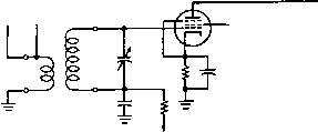 Figure 16 CAPACITIVE BOOST COUPLING CIRCUIT 5ucb circuifs, included within the broadcast receiver ta bring up the stage gain at the high-frequency end of the tuning range, have a tendency to increase the susceptibitity of the receiver to interference from amateur-band transmissions. It is easily seen that a small capacitor at this position will favor the coupling of the higher frequencies. This type of capacitive coupling in the receiver coils will tend to pass amateur high-frequency signals into a receiver tuned to broadcast frequencies. The amount of capacitive coupling may be reduced to eliminate interference by moving the coupling turn further away from the secondary coil. However, a simple wave-trap of the type shown in figure 12, inserted at the antenna input terminal, will generally accomplish the same result and is more to be recommended than reducing the amount of capacitive coupling (which lowers the receiver gain at the high-frequency end of the broadcast band). Should the wave-trap alone not suffice, it will be necessary to resort to a reduction in the coupling capacitance. In some simple broadcast receivers, CEaci-tive coupling is obtained by closely coupled primary and secondary coils, or as a result of running a long primary or antenna lead close to the secondary coil of an unshielded antenna coupler. Phantoms With two strong local carriers applied to a non-linear impedance, the beat note resulting from cross-modulation between them may fall on some frequency within the broadcast band and will be audible at that point. If such a phantom signal falls on a local broadcast frequency, there will be heterodyne interference as well. This is a common occurence with broadcast receivers in the neighborhood of two amateur stations, or an amateur and a police station. It also sometimes occurs when only one of the stations is located in the immediate vicinity. As an example: an amateur signal on 3314 kc. might beat with a local 2414-kc. police carrier to produce a 1100-kc. phantom. If the two carriers are strong enough in the vicinity of a circuit which can cause rectification, the 1100-kc. phantom will be heard in the broadcast band. A poor contact between two oxidized wires can produce rectification. Two stations must be transmitting simultaneously to produce a phantom signal; when either station goes off the air the phantom disappears. Hence, this type of interference is apt to be reported as highly intermittent and might be difficult to duplicate unless a test oscillator is used on location to simulate the missing station. Such interference cannot be remedied at the transmitter, and often the rectification takes place some distance from the receivers. In such occurrences it is most difficult to locate the source of the trouble. It will also be apparent that a phantom might fall on the intermediate frequency of a simple superhet receiver and cause interference of the untunable variety if the manufacturer has not provided an i-f wave-trap in the antenna circuit. This particular type of phantom may, in addition to causing i-f interference, generate harmonics which may be tuned in and out with heterodyne whistles from one end of the receiver dial to the other. It is in this manner that birdies often result from the operation of nearby amateur stations. When one component of a phantom is a steady, unmodulated carrier, only the intelligence present on the other carrier is conveyed to the broadcast receiver. Phantom signals almost always may be identified by the suddenness with which they are interrupted, signalizing withdrawal of one party to the union. This is especially baffling to the inexperienced interference-locater, who observes that the interference suddenly disappears, even though his own transmitter remains in operation. If the mixing or rectification is taking place in the receiver itself, a phantom signal may be eliminated by removing either one of the contributing signals from the receiver input circuit. A wave-trap of the type shown in figure 12, tuned to either signal, will do the trick. If the rectification is taking place outside the receiver, the wave-trap should be tuned to the frequency of the phantom, instead of to one of its components. I-f wave-traps may be built around a 2.5-miIIihenry r-f choke as the inductor, and a compression-type mica padding capacitor. The capacitor should have a capacitance range of 250-525 ft/ifd. for the 175- and 206-kc. intermediate frequencies; 65-175 fifitd. for 2б0-кс. and other intermedi- HANDBOOK Auto Rectification 383 ates lying between 250- and 400-kc; and 17-80 fluid, for 456-, 465-, 495-, and 500-kc. Slightly more capacitance will be required for resonance with a 2.1 millihenry choke. Spurious This sort of interference arises Ernies ions from the transmitter itself. The radiation of any signal (other than the intended carrier frequency) by an amateur station is prohibited by FCC regulations. Spurious radiation may be traced to imperfect neutralization, parasitic oscillations in the r-f or modulator stages, or to broadcast-band variable-frequency oscillators or e.c.o.s. Low-frequency parasitics may actually occur on broadcast frequencies or their near sub-harmonic s, causing direct interference to programs. An all-wave monitor operated in the vicinity of the transmitter will detect these spurious signals. The remedy will be obvious in individual cases. Elsewhere in this book are discussed methods of complete neutralization and the suppression of parasitic oscillations in r-f and audio stages. A-c/d-c Receivers Inexpensive table-model a-c/d-c receivers are particularly susceptible to interference from amateur transmissions. In fact, it may be said with a fair degree of assurance that the majority of BCI encountered by amateurs operating in the 1.8-Mc. to 29-Mc. range is a result of these inexpensive receivers. In most cases the receivers are at fault; but this does not absolve the amateur of his responsibility in attempting to eliminate the interference. Stray Receiver In most cases of interference Rectification to inexpensive receivers, particularly those of the a-c/d-c type, it will be found that stray receiver rectification is causing the trouble. The offending stage usually will be found to be a high-mu triode as the first audio stage following the second detector. Tubes of this type are quite non-linear in their grid characteristic, and hence will readily rectify any r-f signal appearing between grid and cathode. The r-f signal may get to the tube as a result of direct signal pickup due to the lack of shielding, but more commonly will be fed to the tube from the power line as a result of the series heater string. The remedy for this condition is simply to insure that the cathode and grid of the high-mu audio tube (usually a 12SQ7 or equivalent) are at the same r-f potential. This is accomplished by placing an r-f by-pass capacitor with the shortest possible leads directly from grid to cathode, and then adding an impedance in the lead from the volume control to the grid of the HIOH-MU TUBE SUCH AS 12SQ7 TO VOLUME CONTROL 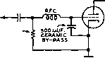 2 TO lo MEO 2 TO 10 MEG. 47 K. i W. - SOOJyuuF.. CERAMIC Figure 17 CIRCUITS FOR ELIMINATING AUDIO-STAGE RECTIFICATION audio tube. The impedance may be an amateur band r-f choke (such as a National R-IOOU) for best results, but for a majority of cases it will be found that a 47,000-obm V-watt resistor in series with this lead will give satisfactory operation. Suitable circuits for such an operation on the receiver are given in figure 17. In many a.c.-d.c. receivers there is no r-f by-pass included across the plate supply rectifier for the set. If there is an appreciable level of r-f signal on the power line feeding the receiver, r-f rectification in the power rectifier of the receiver can cause a particularly bad type of interference which may be received on other broadcast receivers in the vicinity in addition to the one causing the rectification. The soldering of a 0.01-fd. disc ceramic capacitor directly from anode to cathode of the power rectifier (whether it is of the vacuum-tube or selenium-rectifier type) usually will by-pass the r-f signal across the rectifier and thus eliminate the difficidty. Floating Volume Control Shafts Several sets have been encountered where there was only a slightly interfering signal; but, upon placing ones hand up to the volume control, the signal would greatly increase. Investigation revealed that the volume control was installed with its shaft insulated from ground. The control itself was connected to a critical part of a circuit, in many instances to the grid of a high-gain audio Stage. The cure is to install a volume control with all the terminals insulated from the shaft, and then to ground the shaft. BAND COIL, L CAPACITOR, С
METAL BOX I---L---- Figure 18 COIL AND CAPACITOR TABLE FOR A-C LINE TRAPS Power-Line When radio-frequency energy Pickup from a radio transmitter enters a broadcast receiver through the a-c power lines, it has either been fed back into the lighting system by the offending transmitter, or picked up from the air by over-head power lines. Underground lines are seldom responsible for spreading this interference. To check the path whereby the interfering signals reach the line, it is only necessary to replace the transmitting antenna with a dummy antenna and adjust the transmitter for maximum оифиг. If the interference then ceases, overhead lines have been picking up the energy. The trouble can be cleared up by installing a wave-trap or a commercial line filter in the power lines at the receiver. If the receiver is reasonably close to the transmitter, it is very doubtful that changing the direction of the transmitting antenna to right angles with the overhead lines will eliminate the trouble. If, on the contrary, the interference continues when the transmitter is connected to the dummy antenna, radio-frequency energy is being fed directly into the power line by the transmitter, and the station must be inspected to determine the cause. One of the following reasons for the trouble will usually be found: (1) the r-f stages are not sufficiently bypassed and/or choked, (2) the antenna coupling system is not performing efficiently, (3) the power transformers have no electrostatic shields; or, if shields are present, they are ungrounded, (4) power lines are running too close to an antenna or r-f circuits carrying high currents. If none of these causes SHIELD BRAID TO A.C, LINE С с то TRANSMITTER OR RECEIVER г SHIELD BRAID Figure 19 RESONANT POWER-LINE WAVE-TRAP CIRCUIT The resonant type of power-line filter is more effective than the more conventional brute force type of line filter, but requires tuning to the operating frequency of the transmitter. apply, wave-traps must be installed in the power lines at the transmitter to remove r-f energy passing back into the lighting system. The wave-traps used in the power lines at transmitter or receiver must be capable of passing relatively high current. The coils are accordingly wound with heavy wire. Figure 18 lists the specifications for power line wave-trap coils, while figure 19 illustrates the method of connecting these wave-traps. Observe that these traps are enclosed in a shield box of heavy iron or steel, well grounded. All-Wove Each complete-coverage home re-Receivers ceiver is a potential source of annoyance to the transmitting amateur. The novice short-wave broadcast-listener who tunes in an amateur station often considers it an interfering signal, and complains accordingly. Neither selectivity nor image rejection in most of these sets is comparable to those properties in a communication receiver. The result is that an amateur signal will occupy too much dial space and appear at more than one point, giving rise to interference on adjacent channels and distant channels as well. If carrier-frequency harmonics are present in the amateur transmission, serious interference will result at the all-wave receiver. The harmonics may, if the carrier frequency has been so unfortunately chosen, fall directly upon a favorite short-wave broadcast station and arouse warranted objection. The amateur is apt to be blamed, too, for transmissions for which he is not responsible, so great is the public ignorance of short-wave allocations and signals. Owners of all-wave receivers have been quick to ascribe to amateur stations all signals they hear from tape machines and V-wheels, as well as stray tones and heterodyne flutters. The amateur cannot be held responsible when his carrier is deliberately tuned in on an all-wave receiver. Neither is he accountable for the width of his signal on the receiver dial, or for the strength of image repeat points, if it can be proven that the receiver design does not afford good selectivity and image rejection. If he so desires, the amateur (or the owner of the receiver) might sharpen up the received signal somewhat by shortening the receiving antenna. Set retailers often supply quite a sizeable antenna with all-wave receivers, but most of the time these sets perform almost as well with a few feet of inside antenna. The amateur is accountable for harmonics of his carrier frequency. Such emissions are unlawful in the first place, and he must take all steps necessary to their suppression. Practical suggestions for the elimination of harmonics have been given earlier in this chapter under Television Interference. Image Interference In addition to those types of interference already discussed, there are two more which are common to superhet receivers. The prevalence of these types is of great concern to the amateur, although the responsibility for their existence more properly rests with the broadcast receiver. The mechanism whereby image production takes place may be explained in the following manner: when the first detector is set to the frequency of an incoming signal, the high-frequency oscillator is operating on another frequency which differs from the signal by the number of kilocycles of the intermediate frequency. Now, with the setting of these two stages undisturbed, there is another signal which will beat with the high-frequency oscillator to produce an i-f signal. This other signal is the so-called image, which is separated from the desired signal by twice the intermediate frequency. Thus, in a receiver with 175-kc. i.f., tuned to 1000 kc: the h-f oscillator is operating on 1175 kc, and a signal on 1350 kc. (1000 kc. plus 2 x 175 kc.) will beat with this 1175 kc. oscillator frequency to produce the 175-kc. i-f signal. Similarly, when the same receiver is tuned to 1400 kc, an amateur signal on 1750 kc. can come through. If the image appears only a few cycles or kilocycles from a broadcast carrier, heterodyne interference will be present as well. Otherwise, it will be tuned in and out in the manner of a station operating in the broadcast band. Sharpness of tuning will be comparable to that of broadcast stations producing the same a-v-c voltage at the receiver. The second variety of superhet interference is the result of harmonics of the receiver h-f oscillator beating with amateur carriers to produce the intermediate frequency of the receiver. The amateur transmitter will always be found to be on a frequency equal to some harmonic of the receiver h-f oscillator, plus or minus the intermediate frequency. As an example: when a broadcast superhet with 465-kc. i.f. is tuned to 1000 kc, its high-frequency oscillator operates on 1465 kc. The third harmonic of this oscillator frequency is 4395 kc, which will beat with an amateur signal on 3930 kc. to send a signal through the i-f amplifier. The 3930 kc signal would be tuned in at the 1000-kc. point on the dial. Some oscillator harmonics are so related to amateur frequencies that more than one point of interference will occur on the receiver dial. Thus, a 3500-kc. signal may be tuned in at six points on the dial of a nearby broadcast superhet having 175 kc. i.f. and no r-f stage. Insofar as remedies for image and harmonic superhet interference are concerned, it is well to remember that */ the amateur signal did not in the first place reach the input stage of the receiver, the annoyance would not have been created. It is therefore good policy to try to eliminate it by means of a wave-trap or low-pass filter. Broadcast superhets are not always the acme of good shielding, however, and the amateur signal is apt to enter the circuit through channels other than the input circuit. If a wave-trap or filter will not cure the trouble, the only alternative will be to attempt 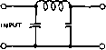 OUTPUT CONSTANT К TYPE 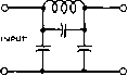 OUTPUT M- DERIVED TYPE 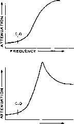 FREQUENCY Figure 20 TYPES OF LOW-PASS FILTERS Filters such as these may be used in the circuit between the antenna and the input of the receiver. ANT. Ll l2 C3-7ЯЯГ\-/ТЯЯГ\-1-о то RECEIVES ANT. POST Сг Сэ -О то RECEIVER SND. POST SND. Figure 21 COMPOSITE LOW-PASS FILTER CIRCUIT This filter is highly effective ir rec/ucing broadcast interference from all high frequency stations, arid requires no tuning. Constants for 400 ohm terminal impedance and 1600 kc. cutoff are as follows! Li, 65 turns no. 22 d.c.c. closewound on I in. dia. form. Lj, 47 turns ditto, not coupled to Lj. Cj, 250 mfd. fixed mica capacitor. C2, 400 fifJ-fd. fixed mica capacitor, C3 and C4, 150 fjp-fd. fixed mica capacitors, former of 5% tolerance. With some receivers, better results will be obtained with a 200 ohm carbon resistor inserted between the filter and antenna post on the receiver. With other receivers the effectiveness will be improved with a 600 ohm carbon resistor placed from the antenna post to the ground post on the receiver. The filter should be placed as close to the receiver terminals as possible. to select a transmitter frequency such that neither image nor harmonic interference will be set up on favorite stations in the susceptible receivers. The equation given earlier may be used to determine the proper frequencies. Low Pass Filters The greatest drawback of the wave-trap is the fact that it is a single-frequency device; i.e.-it may be set to reject at one time only one frequency (or, at best, an extremely narrow band of frequencies). Each time the frequency of the interfering transmitter is changed, every wave-trap tuned to it must be retuned. A much more satisfactory device is the wave filter which requires no tuning. One type, the low-pass filter, passe3 all frequencies below one critical frequency, and eliminates all higher frequencies. It is this property that makes the device ideal for the task of removing amateur frequencies from broadcast receivers. A good low-pass filter designed for maximum attenuation around 1700 kc. will pass all broadcast carriers, but will reject signals originating in any amateur band. Naturally such a device should be installed only in standard broadcast receivers, never in all-wave sets. Two types of low-pass filter sections are shown in figure 20. A composite arrangement comprising a section of each type is more effective than either type operating alone. A composite filter composed of one K-section and one shunt-derived M-section is shown in figure 21, and is highly recommended. The M-section is designed to have maximum attenuation at 1700 kc, and for that reason should be of the close tolerance variety. Likewise, C3 should not be stuffed down inside L, in the interest of compactness, as this will alter the inductance of the coil appreciably, and likewise the resonant frequency. If a fixed 150 (ijjitd. mica capacitor of 5 per cent tolerance is not available for C, a compression trimmer covering the range of 125- 175 (ijiid. may be substituted and adjusted to give maximum attenuation at about 1700 kc. 19-5 HI-FI Interference The rapid growth of high-fidelity sound systems in the home has brought about many cases of interference from a nearby amateur transmitter. In most cases, the interference is caused by stray pickup of the r-f signal by the interconnecting leads of the hi-fi system and audio rectification in the low level stages of the amplifier. The solution to this difficulty, in general, is to bypass and filter all speaker and power leads to the hi-fi amplifier and preamplifier. A combination of a VHF choke and 500 /i/xfd ceramic disc capacitors in each power and speaker lead will eliminate r-f pickup in the high level section of the amplifier. A filter such as shown in figure 17A placed in the input circuit of the first audio stage of the preamplifier will reduce the level of the r-f signal reaching the input circuit of the amplifier. To prevent loss of the higher audio frequencies it may be necessary to decrease the value of the grid bypass capacitor to 50 /i/xfd or so. Shielded leads should be employed between the amplifier and the turntable or f-m tuner. The shield should be. grounded at both ends of the line to the chassis of the equipment, and care should be taken to see diat the line does not approach an electrical half-wavelength of the radio signal causing the interference. In some instances, shielding the power cable to the hi-fi equipment will aid in reducing interference. The framework of the phonograph turntable should be grounded to the chassis of the amplifier to reduce stray r-f pickup in the turntable equipment. CHAPTER TWENTY Transmitter Keying and Control 20-1 Power Systems It is probable that the average amateur station that has been in operation for a number of years will have at least two transmitters available for operation on different frequency bands, at least two receivers or one receiver and a converter, at least one item of monitoring or frequency measuring equipment and probably two, a v.f.o., a speech amplifier, a desk light, and a clock. In addition to the above 8 or 10 items, there must be an outlet available for a soldering iron and there should be one or two additional outlets available for plugging in one or two pieces of equipment which are being worked upon. It thus becomes obvious that 10 or 12 outlets connected to the 115-volt a-c line should be available at the operating desk. It may be practicable to have this number of outlets installed as an outlet strip along the baseboard at the time a new home is being planned and constructed. Or it might be well to install the outlet strip on the operating desk so as to have the flexibility of moving the operating desk from one position to another. Alternatively, the outlet strip might be wall mounted just below the desk top. Power Drain When the power drain of all the Per Outlet items of equipment, other than transmitters, used at the operating position is totalled, you probably will find that 350 to 600 watts will be required. Since the usual home outlet is designed to handle only about 600 watts maximum, the transmitter, unless it is of relatively low power, should be powered from another source. This procedure is desirable in any event so that the voltage supplied to the receiver, frequency control, and frequency monitor will be substantially constant with the transmitter on or off the air. So we come to two general alternative plans with their variations. Plan (A) is the more desirable and also the most expensive since it involves the installation of two separate lines from the meter box to the operating position either when the house is constructed or as an alteration. One line, with its switch, is for the transmitters and the other line and switch is for receivers and auxiliary equipment. Plan ( B)is the more practicable for the average amateur, but its use requires that all cords be removed from the outlets whenever the station is not in use in order to comply with the electrical codes. Figure 1 shows a suggested arrangement for carrying out Plan ( A). In most cases an installation such as this will require approval of the plans by the city or county electrical inspector. Then the installation itself will also require inspection after it has been completed. It will be necessary to use approved outlet boxes at the rear of the transmitter where the cable is connected, and also at the operating bench where the other BX cable connects to the outlet strip. Also, the connectors at the rear of the transmitter will have to be of an approved 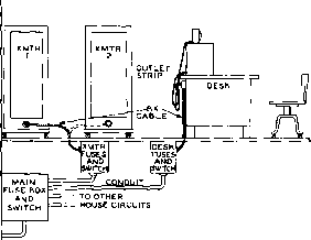 >!- 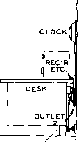 SHORr CORDS FROM RECEIVER.V-FO.. CLOCK, FREQ. METER, ETC. TO OUTLET STRIP, FROM LINE PLAN (A) PLAN (B) Figure 1 THE PLAN (A) POWER SYSTEM A-c line power from the main fuse box in the house is run separatel у to the receiving equipment and to the transmitting equipment. Separate switches and fuse blocks then are available for the transmitters and for the auxiliary equipment. Since the fuses in the boxes at the operating room will be in series with those at the main fuse box, those in the operating room should have a lower rating than those at the main fuse box. Then it will o/woye be possible to rep/ace blown fuses without leaving the operating room. The fuse boxes can conveniently be located alongside one another on the wall of the operating room. Figure 2 THE PLAN (B) POWER SYSTEM This system is less convenient than the (A) system, but does not require extensive rewiring of the electrical system within the house to accommodate the arrangement. Thus it is better for a temporary or semi-permanent installation. In most cases it will be necessary to run an extra conduit from the main fuse box to the outlet from which the transmitter is powered, since the standard arrangement in most houses is to run all fhe outlets in one room (and sometimes all in the house) from a single pair of fuses and leads. type. It is possible also that the BX cable will have to be permanently affixed to the transmitter with the connector at the fuse-box end. These details may be worlted out in advance with the electrical inspector for your area. The general aspects of Plan ( B) are shown in figure 2. The basic difference between the two plans is that (A) represents a permanent installation even though a degree of mobility is allowed through the use of BX for power leads, while plan (B) is definitely a temporary type of installation as far as the electrical inspector is concerned. While it will be permissible in most areas to leave the transmitter cord plugged into the outlet even though it is turned off, the Fire Insurance Underwriters codes will make it necessary that the cord which runs to the group of outlets at the back of the operating desk be removed whenever the equipment is not actually in use. Whether the general aspects of plans (A) or (B) are used it will be necessary to run a number of control wires, keying and audio leads, and an excitation cable from the operating desk to the transmitter. Control and keying wires can best be grouped into a multiple-wire rubber-covered cable between the desk and the transmitter. Such an arrangement gives a good appearance, and is particularly practical if cable connectors are used at each end. High-level audio at a moderate impedance level (600 ohms or below) may be run in the same control cable as the other leads. However, low-level audio can best be run in a small coaxial cable. Small coaxial cable such as RG-58/U or RG-59/U also is quite satisfactory and quite convenient for the signal from the v.f.o. to the r-f stages in the transmitter. Coaxial-cable connectors of the UG series are quite satisfactory for the terminations both for the v-f-o lead and for any low-level audio cables. Checking on To make sure that an outlet will Outlet with a stand the full load of the entire Heavy Load transmitter, plug in an electric heater rated at about 50 per cent greater wattage than the power you expect to draw from the line. If the line voltage does not drop more than 5 volts (assuming a 117-volt line) under load and the wiring does not overheat, the wiring is adequate to supply the transmitter. About 600 watts total drain is the maximum that should be drawn from a 117-volt lighting outlet or circuit. For greater power, a separate pair of heavy conductors should be run right from the meter box. For a 1-kw. phone transmitter the total drain is so great that a 230-voIt split system ordinarily will be required. Most of the newer homes are wired with this system, as are homes utilizing electricity for cooking and heating. With a three-wire system, be sure there is no fuse in the neutral wire at the fuse box. A neutral fuse is not required if both hot legs are fused, and, should a neutral fuse blow, there is a chance that damage to the radio transmitter will result. If you have a high power transmitter and do a lot of operating, it is a good idea to check on your local power rates if you are on a straight lighting rate. In some cities a lower rate can be obtained (but with a higher minimum ) if electrical equipment such as an electric heater drawing a specified amount of current is permanently wired in. It is not required that you use this equipment, merely that it be permanently wired into the electrical system. Naturally, however, there would be no saving unless you expect to occupy the same dwelling for a considerable length of time. Outlet Strips The outlet strips which have been suggested for installation in the baseboard or for use on the rear of a desk are obtainable from the large electrical supply houses. If such a house is not in the vicinity it is probable that a local electrical contractor can order a suitable type of strip from one of the supply house catalogs. These strips are quite convenient in that they are available in varying lengths with provision for inserting a-c line plugs throughout their length. The a-c plugs from the various items of equipment on the operating desk then may be inserted in the outlet strip throughout its length. In many cases it will be desirable to reduce the equipment cord lengths so that they will plug neatly into the outlet strip without an excess to dangle behind the desk. Contactors and The use of power-control con-Reloys tactors and relays often will add considerably to the operating convenience of the station installation. The most practicable arrangement usually is to have a main a-c line switch on the front of the transmitter to apply power to the filament transformers and to the power control circuits. It also will be found quite convenient to have a single a-c line switch on the operating desk to energize or cut the power from the outlet strip on the rear of the operating desk. Through the use of such a switch it is not necessary to remember to switch off a large number of separate switches on each of the items of equipment on the operating desk. The alternative arrangement, and that which is approved by the Underwriters, is to remove the plugs from the wall both for the transmitter and for the operating-desk outlet strip when a period of operation has been completed. While the insertion of plugs or operation of switches usually will be found best for applying the a-c line power to the equipment, the changing over between transmit and receive can best be accomplished through the use of relays. Such a system usually involves three relays, or three groups of relays. The relays and their functions are: (1) power control relay for the transmitter-applies 115-volt line to the primary of the high-voltage transformer and turns on the exciter; (2) control relay for the receiver-makes the receiver inoperative by any one of a number of methods when closed, also may apply power to the v.f.o, and to a keying or a phone monitor; and (3) the antenna changeover relay-connects the antenna to the transmitter when the transmitter is energized and to the receiver when the transmitter is not operating. Several circuits illustrating the application of relays to such control arrangements are discussed in the paragraphs to follow in this chapter. Controlling Transmitter It is necessary, in Power Output order to comply with FCC regulations, that transmitter power output be limited to the minimum amount necessary to sustain communication. This requirement may be met in several ways. Many amateurs have two transmitters; one is capable of relatively high power output for use when calling, or when interference is severe, and the other is capable of considerably less power output. In many cases the lower powered transmitter acts as the exciter for the higher powered stage when full power output is required. But the majority of the amateurs using a high powered equipment have some provision for reducing the plate voltage on the high-level stages when reduced power output is desired. One of the most common arrangements for obtaining two levels of power output involves the use of a plate transformer having a double primary for the high-voltage power supply. The majority of the high-power plate transformers of standard manufacture have just such a dual-primary arrangement. The two primaries are designed for use with either a 115-voit or 230-volt line. When such a transformer is to be operated from a 115-volt line, operation of both 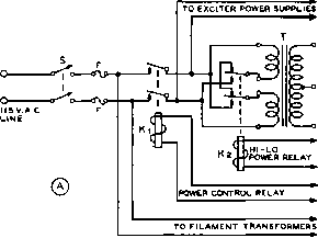 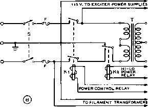 230 VAC. SINGLE PHASE WITH GROUNDED NEUTRAL Figure 3 FULL-VOLTAGE/HALF-VOLTAGE POWER CONTROL SYSTEMS The circulf at (A) Is for use witfi a llS-volt a-c line. Transformer T is of the standard type having two llS-volt primaries; these primaries are connected in series for half-voltage output when the power control relay Kj is energized but the hl-lo relay is not operated. When both relays are energized the full output voltage is obtained. At (B) Is a circuit for use with a standard 230-volt residence line with grounded neutral. The two relays control the output of the power supplies the same as at (A). primaries in parallel will deliver full output from the plate supply. Then when the two primaries are connected in series and still operated from the 115-volt line the output voltage from the supply will be reduced approximately to one half. In the case of the normal class С amplifier, a reduction in plate voltage to one half will reduce the power input to the stage to one quarter. If the transmitter is to be operated from a 230-volt line, the usual procedure is to operate the filaments from one side of the line, the low-voltage power supplies from the other side, and the primaries of the high-voltage transformer across the whole line for full power output. Then when reduced power output is required, the primary of the high-voltage plate transformer is operated from one side to center tap rather than across the whole line. This procedure places 115 volts across the 230-volt winding the same as in the case -discussed in the previous paragraph. Figure 3 illustrates the two standard methods of power reduction with a plate transformer having a double primary, (A) shows the connections for use with a 115-volt line and (B) shows the arrangement for a 230-volt a-c power line to the transmitter. The full-voltage/half-voltage methods for controlling the power input to the transmitter, as just discussed, are subject to the limitation that only two levels of power input (full power and quarter power) are obtainable. In many cases this will be found to be a limitation to flexibility. When tuning the transmitter, the antenna coupling network, or the antenna system itself it is desirable to be able to reduce the power input to the final stage to a relatively low value. And it is further convenient to be able to vary the power input continuously from this relatively low input up to the full power capabilities of the transmitter. The use of a variable-ratio auto-transformer in the circuit from the line to the primary of the plate transformer will allow a continuous variation in power input from zero to the full capability of the transmitter. Variable-Ratio Auto-Transformers There are several types of variable-ratio auro-trans-formers available on the market. Of these, the most common are the Variac manufactured by the General Radio Company, and the Powerstat manufactured by the Superior Electric Company. Both these types of variable-ratio transformers are excellently constructed and are available in a wide range of power capabilities. Each is capable of controlling the line voltage from zero to about 15 per cent above the nominal line voltage. Each manufacturer makes a single-phase unit capable of handling an output power of about 175 watts, one capable of about 750 to 800 watts, and a unit capable of about 1500 to 1800 watts. The maximum power-output capability of these units is available only at approximately the nominal line voltage, and must be reduced to a maximum current limitation when the output voltage is somewhat above or below the input line voltage. This, however, is not an important limitation for this type of Explication since the оифи! voltage seldom will be raised above the line voltage, and when the output voltage is reduced below the line voltage the input to the transmitter is reduced accordingly. 1 ... 35 36 37 38 39 40 41 ... 80 |
||||||||||||||||||||||||||||||||||||||||||||||||||||||||||||||||||||||||||||||||||||||||||||||||||||||||
|
© 2026 AutoElektrix.ru
Частичное копирование материалов разрешено при условии активной ссылки |