 |
 |
 |
| Главная Журналы Популярное Audi - почему их так назвали? Как появилась марка Bmw? Откуда появился Lexus? Достижения и устремления Mercedes-Benz Первые модели Chevrolet Электромобиль Nissan Leaf |
Главная » Журналы » Simple coaxial reflectometer 1 ... 36 37 38 39 40 41 42 ... 80 nSV.A.C. LINE TO EXCITER POWER SUPPLIES TOH.V. POWER SUPPLY POWER CONTROL RELAY DUMMY PLUS FOR STRAIGHT OPERATION TO FILAMENT .TRANSFORMERS 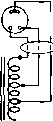 PLUG FOR CABLE TO VARIAC OR POWERSTAT EXTERNAL VARIAC OR POWERSTAT Figure 4 CIRCUIT WITH VARIABLE-RATIO AUTO-TRANSFORMER When /he dummy plug is inserted into the receptacle on the equipment, closing of the power control relay will apply full voltage to the primaries. Vfith the cable from the Variac or Powerstat plugged into the socket the voltage output of the high-voltage power supply may be varied from zero to about 15 per cent obove normal. 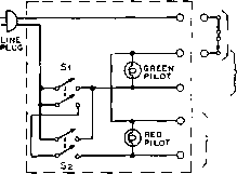 t INTERLOCKS IN TRANSMITTER TRANSMITTER FILAMENT TRANSFORMERS IISV. TO EXCITER AND HIGH-VOLTAGE RELAYS, >ANDTO RECEIVER CONTROL AND ANTENNA CHANGEOVER RELAYS Figure 5 PROTECTIVE CONTROL CIRCUIT Wffh this circuit arrangement either switch may be closed first to light the heaters of all tubes and the filament pilot light. Then when the second switch is closed the high voltage will be applied to the transmitter and the red pilot will light. With a 30-second delay between the closing of the first switch and the c/osing of the second, the rectifier tubes wiff be ac/equofe/yr protecfed. Similarly, the opening of either switch will remove plote voltage from tbe rectifiers while the heaters remain lighted. One convenient arrangement fot using a Variac or Powerstat in conjunction with the high-voltage transformer of a transmitter is illustrated in figure 4. In this circuit a heavy three-wire cable is run from a plug on the transmitter to the Variac or Powerstat. The Variac or Powerstat then is installed so that it is accessible from the operating desk so that the input power to the transmitter may be controlled during operation. If desired, the cable to the Variac or Powerstat may be unplugged from the transmitter and a dummy plug inserted in its place. With the dummy plug in place the transmitter will operate at normal plate voltage. This arrangement allows the transmitter to be wired in such a manner that an external Variac or Powerstat may be used if desired, even though the unit is not available at the time that the transmitter is constructed. Notes on the Use of the Voriac or Powerstat Plate voltage to the modulators may be controlled at the same time as the plate voltage to the final amplifier is varied if the modulator stage uses beam tetrode tubes; variation in the plate voltage on such tubes used as modulators causes only a moderate change in the standing plate current. Since the final amplifier plate voltage is being controlled simultaneously with the modulator plate voltage, the conditions of impedance match will not be seriously upset. In several high power transmitters using this system, and using beam-tetrode modulator tubes, it is possible to vary the plate input from about 50 watts to one kilowatt without a change other than a slight increase in audio distortion at the adjustment which gives the lowest power output from the transmitter. With triode tubes as modulators it usually will be found necessary to vary the grid bias at the same time that the plate voltage is changed. This will allow the tubes to be operated at approximately the same relative point on their operating characteristic when the plate voltage is varied. When the modulator tubes are operated with zero bias at full plate voltage, it will usually be possible to reduce the modulator voltage along with the voltage on the modulated stage, with no apparent change in the voice quality. However, it will be necessary to reduce the audio gain at the same time that the plate voltage is reduced, 20-2 Transmitter Control Methods Almost everyone, when getting a new trans- )1S volt supply for entire transmitter safety switch (see fig. в ) \Sl husky toggle switch on transmitter thermal time-delay relay
standby high volt. (iiav) indicator lights Tune-up switch
all filament transformers exciter h.v. transformer high voltage transformer receiver power transformer с t. protective interlocks transmit-receive switch -Ol1iv, antenna changeover q relay Figure 6 TRANSMITTER CONTROL CIRCUIT Closing Si lights all filaments in the transmitter and starts the time-delay relay in its cycle. When the time-delay relay has operated, closing the transmit-receive switch at the operating position will apply plate power to the transmitter and disable the receiver. A tune-up switch has been provided so that the exciter stages may be tuned without ptate voltage on the final amplifier. mittet on the air, has had the experience of having to throw several switches and pull or insert a few plugs when changing from receive to transmit. This is one extreme in the direction of how not to control a transmitter. At the other extreme we find systems where it is only necessary to speak into the microphone or touch the key to change both transmitter and receiver over to the transmit condition. Most amateur stations are intermediate between the two extremes in the control provisions and use some relatively simple system for transmitter control. In figure 5 is shown an arrangement which protects mercury-vapor rectifiers against premature application of plate voltage without resorting to a time-delay relay. No matter which switch is thrown first, the filaments will be turned on first and off last. However, double-pole switches are required in place of the usual single-pole switches. When assured time delay of the proper interval and greater operating convenience are desired, a group of inexpensive a-c relays may be incoфorated into the circuit to give a control circuit such as is shown in figure 6. This arrangement uses a 115-volt thermal (or motor-operated) time-delay relay and a d-p-d-t 115-volt control relay. Note that the protective interlocks are connected in series with the coil of the relay which applies high voltage to the transmitter. A tune-up switch has been included so that the transmitter may be tuned up as far as the grid circuit of the final stage is concerned before application of high voltage to the final amplifier. Provisions for operating an antenna-changeover relay and for cutting the plate voltage to the receiver when the transmitter is operating have been included. A circuit similar to that of figure 6 but incorporating push-button control of the transmitter is shown in figure 7. The circuit features a set of START-STOP and TRANSMIT-RECEIVE buttons at the transmitter and a separate set at the operating position. The control push buttons operate independently so that either set may be used to control the transmitter. It is only necessary to push the START HANDBOOK Safety Precautions 393 115 volt supply for entpbe transmitter f~ jfuses( start AT OPERATING POSITION stop transmit safetyswitch (see fic.12) ---1 receive I -оп>-1- thermal time-delay relay
all filament transformers protective interlocks high volt (iie vO indicator lights overload relay contacts tune-up switch -o receiver power (-. transformer c.t. -oils v. antenna changeover Q RELAY exciter h.v. transformer hich voltace transformer Figure 7 PUSH-BUTTON TRANSMITTER-CONTROL CIRCUIT Poshing the START button either at the transmitter or at the operating position will light all filaments and start tbe time-delay relay in its cycle. When the cycle has been completed, о fouch of tbe TRANSMIT button will put the transmitter on the air and disable the receiver. Pushing the RECEIVE button will disable the transmitter and restore the receiver. Pushing the STOP button will instantly drop the entire transmitter from the a-c line. If desired, a switch may be placed in series with the lead from the RECEIVE button to the protective interlocks; opening the switch will make it impossible for any person acciJenfo/Zy fo pot fhe fronsmiffer on fhe air. Various other safety provisions, such as the protective-interlock arrangement described in the text have been incorporated. With the circuit arrangement shown far the overload-relay contacts, it is only necessary to use a simple normally-closed d-c relay with a voriable shunt across the coil of the relay. When the current through the coil becomes great enough to open the normally-closed contacts the hold-circuit on the plate-voltage relay will be brolcen and the plate voltage will be removed. If the overload is only momentary, such as a modulation peak or a tank flashover, merely pushing the TRANSMIT button will again put the transmitter on the air. This simple circuit provision eliminates the requirement for expensive overload relays of the mechanically-latching type, but still gives excellent overload protection. button momentarily to light the transmitter filaments and start the time-delay relay in its cycle. When the standby light comes on it is only necessary to touch the TRANSMIT button to put the transmitter on the air and disable the receiver. Touching the RECEIVE button will turn off the transmitter andrestore the receiver. After a period of operation it is only necessary to touch the STOP button at either the tratis-mitter or the operating position to shut down the transmitter. This type of control arrangement is called an electrically-locking push-to- transmit control system. Such systems are frequently used in industrial electronic control. 20-3 Safety Precautions The best way for an operator to avoid ser-ious accidents from the high voltage supplies of a transmitter is for him to use his head, act only with deliberation, and not take unneces- sary chances. However, no one is infallible, and chances of an accident are greatly lessened if certain factors are taken into consideration in the design of a transmitter, in order to protect the operator in the event of a lapse of caution. If there are too many things one must watch out for or keep in mind there is a good chance that sooner or later there will be a mishap; and it only takes one. When designing or constructing a transmitter, the following safety considerations should be given attention. Grounds For the utmost in protection, everything of metal on the front panel of a transmitter capable of being touched by the operator should be at ground potential. This includes dial set screws, meter zero adjuster screws, meter cases if of metal, meter jacks, everything of metal protruding through the front panel or capable of being touched or nearly touched by the operator. This applies whether or not the panel itself is of metal. Do not rely upon the insulation of meter cases or tuning knobs for protection. The В negative or chassis of all plate power supplies should be connected together, and to an external ground such as a waterplpe. Exposed Wires It is not necessary to resort and Components to rack and panel construction in order to provide complete enclosure of all components and wiring of the transmitter. Even with metal-chassis construction it is possible to arrange things so as to incorporate a protective shielding housing which will not interfere with ventilation yet will prevent contact with all wires and components carrying high voltage d.c. or a.c, in addition to offering shielding action. If everything on the front panel is at ground potential (with respect to external ground) and all units are effectively housed with protective covers, then there is no danger except when the operator must reach into the interior part of the transmitter, as when changing coils, neutralizing, adjusting coupling, or shooting trouble. The latter procedure can be made safe by making it possible for the operator to be absolutely certain that all voltages have been turned off and that they cannot be turned on either by short circuit or accident. This can be done by incorporation of the following system of main primary switch and safety signal lights. Combined Safety The common method of Signal and Switch using red pilot lights to show when a circuit is on is useless except from an ornamental standpoint. When the red pilot is not lit it usually means that the circuit is turned off, but it can e.BV.TO GREEN PILOT LIGHTS ON FRONT PANEL AND ON EACH CHASSIS : FIL. TRANS MAIN IIS V. SUPPLY DPDT. SWITCH TIS V.A.C. TO ENTIRE TRANSMITTER Figure 8 COMBINED MAIN SWITCH AND SAFETY SIGNAL When shutting down the transmitter, throw the main switch to neutral. If work is to be done on the transmitter, throw the switch all the way to pilot, thus turning on the green pilot lights on the panel and on each chassis, and insuring thot no voltage can exist On the primary of any transformer, even by virtue of a short or accidental ground. mean that the circuit is on but the lamp is burned out or not making contact. To enable you to touch the tank coils in your transmitter with absolute assurance that it is impossible for you to obtain a shock except from possible undischarged filter condensers (see following topic for elimination of this hazard), it is only necessary to incorporate a device similar to that of figure 8. It is placed near the point where the main 110-volt leads enter the room (preferably near the door) and in such a position as to be inaccessible to small children. Notice that this switch breaks both leads; switches that open just one lead do not afford complete protection, as it is sometimes possible to complete a primary circuit through a short or accidental ground. Breaking just one side of the line may be all right for turning the transmitter on and off, but when you ate going to place an arm inside the transmitter, both 110-volt leads should be broken. When you are all through working your transmitter for the time being, simply throw the main switch to neutral. When you find it necessary to work on the transmitter ot change coils, throw the switch so that the green pilots light up. These can be ordinary 6-3-volt pilot lamps behind green bezels or dipped in green lacquer. One should be placed on the front panel of the transmitter; others should be placed so as to be easily visible when changing coils ot making adjustments requiring the operator to reach inside the transmitter. For 100 per cent protection, just obey the following rule: never work on the transmitter or reach inside any protective cover except when the green pilots are glowing. To avoid confusion, no other green pilots should be used on the transmitter; if you want an indicator jewel to show when the filaments are lighted, use amber instead of green. Safety Bleeders Filter capacitors of good quality hold their charge for some time, and when the voltage is more than 1000 volts it is just about as dangerous to get across an undischarged 4-/ifd. filter capacitor as it is to get across a high-voltage supply that is turned on. Most power supplies 1псофога1е bleeders to improve regulation, but as these are generally wire-wound resistors, and as wire-wound resistors occasionally open up without apparent cause, it is desirable to incorporate an auxiliary safety bleeder across each heavy-duty bleeder. Carbon resistors will not stand much dissipation and sometimes change in value slightly with age. However, the chance of their opening up when run well within their dissipation rating is very small. To make s re that all capacitors are bled, it is best to short each one with an insulated screwdriver. However, this is sometimes awkward and aWays inconvenient. One can be virtually sure by connecting auxiliary carbon bleeders across all wire-wound bleeders used on supplies of 1000 volts ot more. For every 500 volts, connect in series a 500,000-ohm 1-watt carbon resistor. The drain will be negligible (1 ma.) and each resistor will have to dissipate only 0.5 watt. Under these conditions the resistors will last indefinitely with little chance of opening up. For a 1500-volt supply, connect three 500,000-ohm resistors in series. If the voltage exceeds an integral number of 500 volt divisions, assume it is the next higher integral value; for instance, assume 1800 volts as 2000 volts and use four resistors. Do not attempt to use fewer resistors by using a higher value for the resistors; not over 500 volts should appear across any single 1-watt resistor. In the event that the regular bleeder opens up, it will take several seconds for the auxiliary bleeder to drain the capacitors down to a safe voltage, because of the very high resistance. Therefore, it is best to allow 10 or 15 seconds after turning off the plate supply before attempting to work on the ttansmitter. If a 0-1 d-c milliammeter is at hand, it may be connected in series with the auxiliary bleeder to act as a high voltage voltmeter. Hot Adjustments Some amateurs contend that it is almost impossible to make certain adjustments, such as coupling and neutralizing, unless the transmitter is running. The best, thing to do is to make all neutralizing and coupling devices adjustable from the front panel by means of flexible control shafts which are broken with insulated couplings to permit grounding of the panel bearing. If your particular transmitter layout is such that this is impracticable and you refuse to throw the main switch to make an adjustment -throw the main switch-take a reading-throw the main switch-make an adjustment-and so on, then protect yourself by making use of long adjusting rods made from V2-inch dowel sticks which have been wiped with oil when perfectly free from moisture. If you are addicted to the use of pickup loop and flashlight bulb as a resonance and neutralizing indicator, then fasten it to the end of a long dowel stick and use it in that manner. Protective Interlocks With the increasing tendency toward construction of transmitters in enclosed steel cabinets a transmitter becomes a particularly lethal device unless adequate safety provisions have been incorporated. Even with a combined safety signal and switch as shown in figure 8 it is still conceivable that some person unfamiliar with the transmitter could come in contact with high voltage. It is therefore recommended that the transmitter, wherever possible, be built into a complete metal housing or cabinet and that all doors or access covers be provided with protective interlocks (all interlocks must be connected in series) to remove the high voltage whenever these doors or covers are opened. The term high voltage should mean any voltage above approximately 150 volts, although it is still possible to obtain a serious burn from a 150-volt circuit under certain circumstances. The 150-volt limit usually will mean that grid-bias packs as well as high-voltage packs should have their primary circuits opened when any interlock is opened. 20-4 Transmitter Keying The carrier from a c-w telegraph transmitter must be broken into dots and dashes for the transmission of code characters. The carrier signal is of constant amplitude while the key is closed, and is entirely removed when the key is open. When code characters are being transmitted, the carrier may be considered as being modulated by the keying. If the change from the no-output condition to full-output, or vice versa, occurs too ridly, the rectangular pulses which form the keying characters contain high-frequency components which take up a wide frequency band as sidebands and are heard as clicks. The cure for transient key clicks is relatively simple, although one would not believe it, judging from the hordes of clicky, snappy signals heard on the air. To be capable of transmitting code characters and at the same time not splitting the eardrums of neighboring amateurs, the c-w transmitter MUST meet two important specifications. 1- It must have no parasitic oscillations either in the stage being keyed or in any succeeding stage. 2- It must have some device in the keying circuit capable of shaping the leading and trailing edge of the waveform. Both these specifications must be met before the transmitter is capable of c-w operation. Merely turning a transmitter on and off by the haphazard insertion of a telegraph key in some power lead is an invitation to trouble. The two general methods of keying a transmitter are those which control the excitation to the keyed amplifier, and those which control the plate or screen voltage applied to the keyed amplifier. Key-Click Key-click elimination is accom-Elimination plished by preventing a too-rapid make-and-break of power to the antenna circuit, rounding off the keying characters so as to limit the sidebands to a value which does not cause interference to adjacent channels. Too much lag will prevent fast keying, but fortunately key clicks can be practically eliminated without limiting the speed of manual (hand) keying. Some circuits which eliminate key clicks introduce too much time-lag and thereby add tails to the dots. These tails may cause the signals to be difficult to copy at high speeds. Location of Considerable thought should be Keyed Stage given as to which stage in a transmitter is the proper one to key. If the transmitter is keyed in a stage close to the oscillator, the change in t-f loading of the oscillator will cause the oscillator to shift frequency with keying. This will cause the signal to have a distinct chirp. The chirp will be multiplied as many times as the frequency of the oscillator is multiplied. A chirpy oscillator that would be passable on 80 meters would be unusable on 28 Mc. c.w. Keying the oscillator itself is an excellent way to run into keying difficulties. If no key click filter is used in the keying circuit, the transmitter will have bad key clicks. If a key click filter is used, the slow rise and decay of oscillator voltage induced by the filter action will cause a keying chirp. This action is 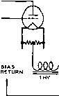 keyed tube pO.lJUf JioOn. .004 =L (at key) -Ю-в Figure 9 CENTER-TAP KEYING WITH CLICK FILTER The constants shown above are suggested as starting values; considerable variation in these values can be expected for optimum keying of amplifiers of different operating conditions. It is suggested that a keying relay be substituted for the key in the circuit above wherever practicable. true of all oscillators, whether electron coupled or crystal controlled. The more amplifier or doubler stages that follow the keyed stage, the mote difficult it is to hold control of the shape of the keyed waveform. A heavily excited doublet stage ot class С stage acts as a peak clipper, tending to square up a rounded keying impulse, and the cumulative effect of several such stages cascaded is sufficient to square up the keyed waveform to the point where bad clicks are reimposed on a clean signal. A good rule of thumb is to never key back farther than one stage removed from the final amplifier stage, and never key closer than one stage removed from the frequency controlling oscillator of the transmitter. Thus there will always be one isolating stage between the keyed stage and the oscillator, and one isolating stage between the keyed stage and the antenna. At this point the waveform of the keyed signal may be most easily controlled. Keyer Circuit In the first place it may be es-Requirements tablished that the majority of new design transmitters, and many of those of older design as well, use a medium power beam tetrode tube either as the output stage or as the exciter for the output stage of a high power transmitter. Thus the transmitter usually will end up with a tube such as type 2E26, 807, 6146, 813, 4-65A, 4E27/257B, 4-125A or similar, or one of these tubes will be used as the stage just ahead of the ouфut stage. Second, it may be established that it is undesirable to key further down in the transmitter chain than the stage just ahead of the final 50 ma. sele-nium rectifier .47,1 i m (break) i m(make) eye cathode of ° ° keyed stage о j -t 10 о о laov, о lookl о iw w 47k,2w I I 1 *--lM/>-Ш * Ф- JRFC ;г.5 mh 100 ~1JJUF -01- .005 mica T to хмт gnd. stancor paa42l 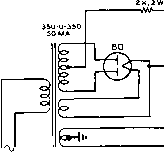 R.F. TUBE 45/2A3 о о о 45/2АЗ 470 к' 470k,IW IM 470k,aSW /UTN TX--CTT ; I w~w J=4 pz.SMH °1 I.ров I T - 1 /cv I loojuJF nr,tr T005 ® Figure 10 VACUUM TUBE KEYERS FOR CENTER-TAP KEYING CIRCUITS The type A keyer is suitable for keying stages running up to 1250 volts on the plate. Two 2A3 or 6A3 tubes can safely key 160 milliamperes of cathode current. The simple 6Y6 keyer in figure В is for keying stages running up to 650 volts on tbe plate. A single 6Y6 can key 80 milliamperes. Two in parallel may be used for plate currents under 160 ma. If softer keying is desired, the 500-fifJ.fd. mica conJenser should be increosed to .001 Md. amplifier. If a low-level stage, which is followed by a series of class С amplifiers, is keyed, serious transients will be generated in the ouфut of the transmitter even though the keyed stage is being turned on and off very smoothly. This condition arises as a result of pulse sharpening, which has been discussed previously. Third, the output from the stage should be completely cut off when the key is up, and the time constant of the rise and decay of the keying wave should be easily controllable. Fourth, it should be possible to make the rise period and the decay period of the keying wave approximately equal. This type of keying envelope is the only one tolerable for commercial work, and is equally desirable for obtaining clean cut and easily readable signals in amateur work. Fifth, it is desirable that the keying circuit be usable without a keying relay, even when a high-power stage is being keyed. Last, for the sake of simplicity and safety, it should be possible to ground the frame of the key, and yet the circuit should be such that placing the fingers across the key will not result in an electrical shock. In other words, the keying circuit should be inherently safe. All these requirements have been met in the keying circuits to be described. 20-5 Cathode Keying The lead from the cathode or center-tap connection of the filament of an r-f amplifier can be opened and closed for a keying circuit. Such a keying system opens the plate voltage circuit and at the same time opens the grid bias return lead. For this reason, the grid circuit is blocked at the same time the plate circuit is opened. This helps to reduce the backwave that might otherwise leak through the keyed stage. The simplest cathode keying circuit is illustrated in figure 9, where a key-click filter is employed, and a hand key is used to break the circuit. This eimple keying circuit is not о  rfc Iri Ы= i 2.5 MH 1плг IOOJUJJF-= I00K,2W 7Г -BLOCKING BIAS Figure 11 SIMPLE BLOCKED-GRID KEYING SYSTEM The blocking bias must be sufficient to cutoff plate current to the amplifier stage in the presence of the excitation voltage. Rj Is normal bias resistor for the tube. 1 should be adjusted for correct keying waveform. о о о о 2.5 MH 200 2W Цу-гтппр. ,00, HI-MU TRIODE (811-A ETC.) 7Г 7Г Figure 12 SELF-BLOCKING KEYING SYSTEM FOR HIGH-MU TRIODE Rl and Cl adjusted for correct keying waveform. Rl is bias resistor of tube. recommended for general use, as considerable voltage will be developed across the key when it is open. An electronic switch can take the place of the hand key. This will remove the danger of shock. At the same time, the opening and closing characteristics of the electronic switch may easily be altered to suit the particular need at hand. Such an electronic switch is called a vacuum tube keyer. Low internal resistance triode tubes such as the 45, 6A3, or 6AS7 are used in the keyer. These tubes act as a very high resistance when sufficient 807, 6 146, ETC 100 JUJJF LOW POWER BUFFER RFC&O {aAC7 ETC.) I-f. 2.5 МНП 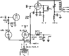 Figure 13 TWO-STAGE BLOCKED-GRID KEYER A seporofe filament transformer must be used for the 6J5, as its filament is at a potential of -400 volts. blocking bias is applied to them, and as a very low resistance when the bias is removed. The desired amount of lag or cushioning effect can be obtained by employing suitable resistance and capacitance values in the grid of the keyer tube(s). Because very little spark is produced at the key, due to the small amount of power in the key circuit, sparking clicks are easily suppressed. One type 45 tube should be used for every 50 ma. of plate current. Type 6B4G or 2A3 tubes may also be used; allow one 6B4G tube for every 80 ma. of plate current. Because of the series resistance of the keyer tubes, the plate voltage at the keyed tube will be from 30 to 60 volts less than the power supply voltage. This voltage appears as cathode bias on the keyed tube, assuming the bias return is made to ground, and should be taken into consideration when providing bias. Some typical cathode circuit vacuum tube keying units are shown in figure 10. 20-6 Grid Circuit Keying Grid circuit, or blocked grid keying is another effective method of keying a c-w transmitter. A basic blocked grid keying circuit is shown in figure 11. The time constant of the keying is determined by the RC circuit, which also forms part of the bias circuit of the tube. Vthen the key is closed, operating bias is developed by the flow of grid current through Rj When the key is open, sufficient fixed bias is applied to the tube to block it, preventing the stage from functioning. If an un-neutralized EXC- 807, ETC. 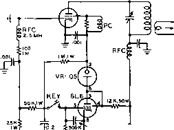 soo JUJUF MICA +S0OV. preventing any backwave emission. The first keyed stage may be the oscillatot, or a low powered buffer. The last keyed stage may be the driver stage to the power amplifier, or the amplifier itself. Since the circuit is so proportioned that the lower powered stage comes on first and goes off last, any keying chirp in the oscillatot is not emitted on the air. Keying lag is applied to the high powered keyed stage only. 20-7 Screen Grid Keying Figure 14 SINGLE-STAGE SCREEN GRID KEYER FOR TETRODE TUBES tetrode is keyed by this method, there is the possibility of a considerable backwave caused by r-f leakage through the gtid-plate capacity of the tube. Certain hi- triode tubes, such as the 811-A and the 805, automatically block themselves when the grid return circuit is opened. It is merely necessary to insert a key and associated key click filter in the grid return lead of these tubes. No blocking bias supply is needed. This circuit is shown in figure 12. A more elaborate blocked-grid keying system has been developed by WIDX, and was shown in the February, 1954 issue of QST magazine. This highly recommended circuit is shown in figure 13. Two stages ate keyed. The screen circuit of a tetrode tube may be keyed for c-w operation. Unfortunately, when the screen grid of a tetrode tube is brought to zero potential, the tube still delivers considerable output. Thus it is necessary to place a negative blocking voltage on the screen grid to reduce the backwave through the tube. A suitable keyet circuit that will achieve this was developed by W6DTY, and was described in the February, 1953 issue of CQ magazine. This circuit is shown in figure 14. A 6L6 is used as a combined clamper tube and keying tube. When the key is closed, the 6L6 tube has blocking bias applied to its control grid. This bias is obtained from the rectified grid bias of the keyed tube. Screen voltage is applied to the keyed stage through a screen dropping resistor and a VR-105 regulator tube. When the key is open, the 6L6 is no longer cut-off, and conducts heavily. The voltage drop across the dropping resistor caused by the heavy plate current of the 6L6 lowers the voltage on the VR-105 tube until it is extin- Figore 15 TOP VIEW OF SCREEN GRID KEYER SHOWN IN FIGURE 16  LOW POWER BUFFER 6AG7 807.ЁТС.
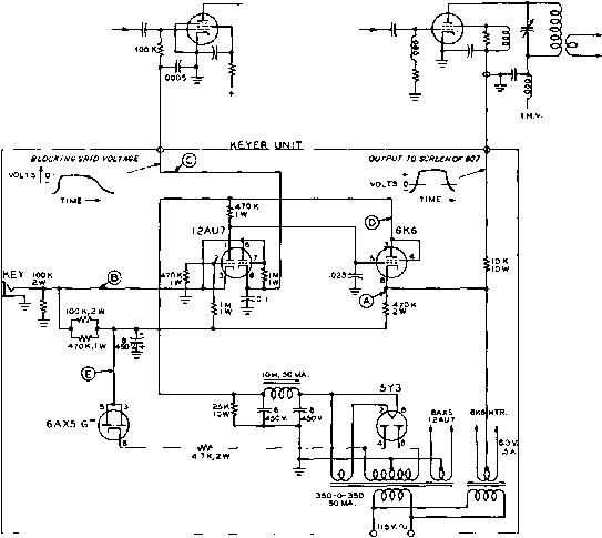 Figure 16 TWO-STAGE SCREEN GRID KEYER UNIT guished, removing the screen voltage from the tetrode r-f tube. At the same time, rectified grid bias is applied to the screen of the tetrode through the 1 megohm resistor between screen and key. This voltage effectively cuts off the screen of the tetrode until the key is closed again. The RC circuit in the grid of the 6L6 tube determines the keying characteristic of the tetrode tube. A more elaborate screen grid keyer is shown in figures 15 and 16. This keyer is designed to block-grid key the oscillator or a low powered buffer stage, and to screen key a medium powered tetrode tube such as an 807, 2E26 or 6146. The unit described includes a simple dual voltage power supply for the positive screen voltage of the tetrode, and a negative supply for the keyer stages, A бКб is used as the screen keyer, and a 12AU7 is used as a cathode follower and grid block keyer. As in the WIDX keyer, this keyer turns on the exciter a moment before the tetrode stage is turned on. The tetrode stage goes off an instant before the exciter does. Thus any keying chirp of the oscillator is effectively removed from the keyed signal. By listening in the receiver one can hear the exciter stop operating a fraction of a second after the tetrode stage goes off. In fact, during rapid keying, the exciter may be heard as a steady signal in the receiver, as it has appreciable time lag in the keying circuit. The clipping effect of following stages has a definite hardening effect on this, however. 20-8 Differential Keying Circuits Excellent waveshaping may be obtained by a differential keying system whereby the master oscillator of the transmitter is turned 1 ... 36 37 38 39 40 41 42 ... 80 |
|
© 2026 AutoElektrix.ru
Частичное копирование материалов разрешено при условии активной ссылки |