 |
 |
 |
| Главная Журналы Популярное Audi - почему их так назвали? Как появилась марка Bmw? Откуда появился Lexus? Достижения и устремления Mercedes-Benz Первые модели Chevrolet Электромобиль Nissan Leaf |
Главная » Журналы » Simple coaxial reflectometer 1 ... 37 38 39 40 41 42 43 ... 80 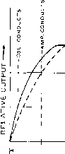 KEY IS DEPRESSED DURING THIS TIME I l-i-TRANSMITTER IS ON THE AlH DURING THIS TIME. 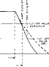 170 к -250 v. - J KE 6AL5 BLOCKING DIODES TO CATHODE CIRCUIT OF KEYED STAGE 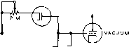 TUBE KEYER Figure 18 BLOCKING DIODES EMPLOYED TO VARY TIME CONSTANT OF MAKE AND-BREAK CHARACTERISTICS OF VACUUM TUBE KEYER Figure 17 TIME SEQUENCE OF A DIFFERENTIAL KEYER on a moment before the rest of the stages are energized, and remains on a moment longer than the other stages. The chirp or frequency shift associated with abrupt switching of the oscillator is thus removed from the emitted signal. In addition, the differential keyet can apply wave shaping to the amplifier section of the transmitter, eliminating the click caused by rapid keying of the latter stages. The ideal keying system would perform as illustrated in figure 17. When the key is closed, the oscillator reaches maximum output almost instantaneously. The following stages reach maximum output in a fashion determined by the waveshaping circuits of the keyer. When the key is released, the output of the amplifier stages starts to decay in a predetermined manner, followed shortly thereafter by cessation of the oscillator. The overall tesult of these actions is to provide relatively soft make and break to the keyed signal, meanwhile preventing oscillator frequency shift during the keying sequence. The rates of charge and decay in a typical R-C keying circuit may be varied independently of each other by the blocking diode system of figure 18. Each diode permits the charging current of the timing capacitor to flow through only one of the two variable potentiometets, thus permitting independent adjustment of the make and break characteristics of the keying system, A practical differential keying system de- veloped by WIICP (Feb., 1956 QST) is shown in figure 19. A 6AL5 switch tube turns the oscillator on before the keying action starts, and holds it on until after the keying sequence is completed. Time constant of the keying cycle is determined by values of С and R. When the key is open, a cut-off bias of about -110 volts is applied to the screen grid circuits of the keyed stages. When the key is closed, the screen grid voltage rises to the normal value at a rate determined by the time constant R-C. Upon opening the key again, the screen voltage returns to cut-off value at the predetermined rate. The potentiometer Rl serves as an output control, varying the minimum internal resistance of the 12BH7 keyer tube, and is a useful device to limit power input during tune-up periods. Excitation to the final amplifier stage may be controlled by the screen potentiometer R3 in the second buffer stage. An external bias source of approximately -120 volts at 10 milliamperes is required for operation of the keyer, in addition to the 300-volt screen supply. Blocking voltage may be removed from the oscillator for zeroing purposes by closing switch SI, rendering the diode switch inoperative. A second popular keying system is shown in figure 20, and is widely used in many Johnson transmitters. Grid block keying is used on tubes V2 and V3. A waveshaping filter consisting of R2, R3, and Cl is used in the keying control circuit of V2 and V3. To avoid chirp when the oscillator (Vi) is keyed, the keyer tube V4 allows the oscillator to start quickly--before V2 and V3 start OSCILLATOR BUFFER 1 BUFFER г ZERO BEAT i 6AL5 7 10 к 50 К ZW 12BH7 25K -120V. OUTPUT CONTROL % 100 к 1.41 Figure 19 DIFFERENTIAL KEYING SYSTEM WITH OSCILLATOR SWITCHING DIODE OSCILLATOR 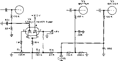 VFO HOLD -50 V Figure 20 DIFFERENTIAL KEYER EMPLOYED IN JOHNSON TRANSMITTERS conducting-and ten continue operating until atter V2 and V3 have stopped conducting. Potentiometer Rl adjusts the hold time for VFO operation after the key is opened. This may be adjusted to cut off the VFO between marks of keyed characters, thus allowing rapid break-in operation. Radiation, Propagation and Transmission Lines Radio waves are electromagnetic waves similar in nature but much lower in frequency than light waves or heat waves. Such waves represent electric energy traveling through space. Radio waves travel in free space with the velocity of light and can be reflected and refracted much the same as light waves. Radiation from an Antenna Alternating current passing through a conductor creates an alrernating electromagnetic field around that conductor. Energy is alternately stored in the field, and then returned to the conductor. As the frequency is raised, more and more of the energy does not return to the conductor, but instead is radiated off into space in the form of electromagnetic waves, called radio waves. Radiation from a wire, or wires, is materially increased whenever there is a sudden change in the electrical constants of the line. These sudden changes produce reflection, which places standing waves on the line- When a wire in space is fed radio frequency energy having a wavelength of approximately 2.1 times the length of the wire in meters, the wire resonates as a half-wave dipole antenna at that wavelength or frequency. The greatest possible change in the electrical constants of a line is that which occurs at the open end of a wire. Therefore, a dipole has a great mismatch at each end, producing a high degree of reflection. We say that the ends of a dipole are terminated in an infinite impedance. A returning wave which has been reflected meets the next incident wave, and the voltage and current at any point along the antenna are the vector sum of the two waves. At the ends of the dipole, the voltages add, while the currents of the two waves cancel, thus producing high voltage and low current at the ends of the dipole or half wave section of wire. In the same manner, it is found that the currents add while the voltages cancel at the center of the dipole. Thus, at the center there is high current but low voltage. Inspection of figure 1 will show that the current in a dipole decreases sinusoidally towards either end, while the voltage similarly increases. The voltages at the two ends of the antenna are 180° out of phase, which means that the polarities are opposite, one being plus while the other is minus at any instant. A curve representing either the voltage or current on a dipole represents a standing wave on the wire. Radiation from Radiation can and does take Sources other place from sources other than than Antennos antennas. Undesired radiation can take place from open-wire n center -----Г currenj I CURRENT -hm.r-wave antenna- SHOWlNe how STANOINe waves exist on a horizontal antenna. current is maximum at center. voltace is maximum at ends. voltace Figure 1 STANDING WAVES ON A RESONANT ANTENNA transmission lines, both from single-wire lines and from lines comprised of more than one wire. In addition, radiation can be made to take place in a very efficient manner from electromagnetic horns, from plastic lenses or from electromagnetic lenses made up of spaced conducting planes, from slots cut in a piece of metal, from dielectric wires, or from the open end of a wave guide. Directivity of The radiation from any phys-Radiotion ically practicable radiating system is directive to a certain degree. The degree of directivity can be enhanced or altered when desirable through the combination of radiating elements in a prescribed manner, through the use of reflecting planes or curved surfaces, or through the use of such systems as mentioned in the preceding paragraph. The construction of directive antenna arrays is covered in detail in the chapters which follow. Polarization Like light waves, radio waves can have a definite polarization. In fact, while light waves ordinarily have to be reflected or passed through a polarizing medium before they have a definite polarization, a radio wave leaving a simple radiator will have a definite polarization, the polarization being indicated by the orientation of the electric-field component of the wave. This, in turn, is determined by the orientation of the radiator itself, as the magnetic-field component is always at right angles to a linear radiator, and the electric-field component is always in the same plane as the radiator. Thus we see that an antenna that is vertical with respect to the earth will transmit a vertically polarized wave, as the electrostatic lines of force will be vertical. Likewise, a simple horizontal antenna will radiate horizontally polarized waves. Because the orientation of a simple linear radiator is the same as the polarization of the waves emitted by it, the radiator itself is referred to as being either vertically or horizontally polarized. Thus, we say that a horizontal antenna is horizontally polarized. Figure 2A illustrates the fact that the polarization of the electric field of the radiation from a vertical dipole is vertical. Figure 2B, on the other hand, shows that the polarization of electric-field radiation from a vertical slot radiator is horizontal. This fact has been utilized in certain commercial FM antennas where it is desired to have horizontally polarized radiation but where it is more convenient to use an array of vertically stacked slot arrays. If the metallic sheet is bent into a cylinder with the slot on one side, substantially omnidirectional horizontal coverage is obtained with horizontally-polarized radiation when the cylinder with the slot in one side is oriented vertically. An arrangement of this type is shown in figure 2C. Several such cylinders may be stacked vertically to reduce high-angle radiation and to concentrate the radiated energy at the useful low radiation angles. In any event the polarization of radiation from a radiating system is parallel to the electric field as it is set up inside or in the vicinity of the radiating system. 21-2 General Character- istics of Antennas All antennas have certain general characteristics to be enumerated. It is the result of differences in these general characteristics which makes one type of antenna system most suitable for one type of application and another type best for a different application. Six of the more important characteristics are: (1) polarization, (2) radiation resistance, (3) horizontal directivity, (4) vertical directivity, (5) bandwidth, and (6) effective power gain. The polarization of an antenna or radiating system is the direction of the electric field and has been defined in Section 21-1. The radiation resistance of an antenna system is normally referred to the feed point in an antenna fed at a current loop, or it is referred to a current loop in an antenna system fed at another point. The radiation resistance is that value of resistance which, if inserted in series with the antenna at a current loop, would dissipate the same energy as is actually radiated by the antenna if the antenna current at the feed point were to remain the same. The horizontal and vertical directivity can best be expressed as a directive pattern which Figure 2 ANTENNA POLARIZATION The polarization (electric field) of the radiation from a resonant dipole such as shown at (A) above is parallel to the length of the radiator. In the case of a resonant slot cut in a sheet of metal and used as a radiator, the polarization (of the electric field) is perpendicular to the length of fhe slot. In both cases, however, the polarization of the radiated field is parallel to the potential gradient of the radiator; in the case of the dipole the electric lines of force are from end to end, while in the case of the slot the field is across the sides ot the slot. The metallic sheet containing the slot may be farmed into a cylinder to make up the radiator shown at (C). With this type of radiator fhe radiated field will be horizontally polarized even though fhe radiator is mounted vertically. electric (polarization) vertical
electric field (polarization) horizontal 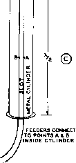 is a grh showing the relative radiated field intensity against azimuth angle for horizontal directivity and field intensity against elevation angle for vertical directivity. The bandwidth of an antenna is a measure of its ability to operate within specified limits over a range of frequencies. Bandwidth can be expressed either operating frequency plus-or-minus a specified per cent of operating frequency or operating frequency plus-or-minus a specified number of megacycles for a certain standing-wave-ratio limit on the transmission line feeding the antenna system. The effective power gain or directive gain of an antenna is the ratio between the power required in the specified antenna and the power required in a reference antenna (usually a half-wave dipole) to attain the same field strength in the favored direction of the antenna under measurement. Directive gain may be expressed either as an actual power ratio, or as is more common, the power ratio may be expressed in decibels. Physical Length If the ctoss section of the of a Half-Wave conductor which makes up Antenna the antenna is kept very small with respect to the antenna length, an electrical half wave is a fixed percentage shorter than a physical half-wavelength. This percentage is approximately 5 per cent. Therefore, most linear half-wave antennas are close to 95 per cent of a half wavelength long physically. Thus, a half-wave antenna resonant at exactly 80 meters would be one-half of 0.95 times 80 meters in length. Another way of saying the same thing is that a wire resonates at a wavelength of about 2.1 times its length in meters. If the diameter of the conductor begins to be an appreciable fraction of a wavelength, as when tubing is used as a v-h-f radiator, the factor becomes slightly less than 0.95- For the use of wire and not tubing on frequencies below 30 Mc, however, the figure of 0.95 may be taken as accurate. This assumes a radiator removed from surrounding objects, and with no bends. Simple conversion into feet can be obtained by using the factor 1.56. To find the physical length of a half-wave 80-metet antenna, we multiply 80 times 1.56, and get 124.8 feet for the length of the radiator. It is more common to use frequency than wavelength when indicating a specific spot in the radio spectrum. For this reason, the relationship between wavelength and frequency must be kept in mind. As the velocity of radio waves through space Is constant at the speed of light, it will be seen that the more waves that pass a point per second (higher frequency), the closer together the peaks of those waves must be (shorter wavelength). Therefore, the higher the frequency, the lower will be the wavelength. A radio wave in space can be compared to a wave in water. The wave, in either case, has peaks and troughs. One peak and one trough constitute a full wave, or one wavelength. Frequency describes the number of wave cycles or peaks passing a point per second. Wavelength describes the distance the wave travels through space during one cycle or oscillation of the antenna current; it is the distance in meters between adjacent peaks or adjacent troughs of a wave train. As a radio wave travels 300,000,000 meters a second (speed of light), a frequency of 1 cycle per second corresponds to a wavelength of 300,000,000 meters. So, if the frequency is multiplied by a million, the wavelength must be divided by a million, in order to maintain their correct ratio. A frequency of 1,000,000 cycles per second (1,000 kc.) equals a wavelength of 300 meters. Multiplying frequency by 10 and dividing wavelength by 10, we find: a frequency of 10,000 kc. equals a wavelength of 30 meters. Multiplying and dividing by 10 again, we get: a frequency of 100,000 kc. equals 3 meters wavelength. Therefore, to change wavelength to frequency (in kilocycles), simply divide 300,000 by the wavelength in meters (Л). 300,000 Fkc =- 300,000 Ffcc Now that we have a simple conversion formula for converting wavelength to frequency and vice versa, we can combine it with our wavelength versus antenna length formula, and we have the following: Length of a half-wave radiator made from wire (no. 14 to no. 10): 3.5-Mc. to 30-Mc. bands 468 Length in feet = Freq. in Mc. 50-Mc. band Length in feet = Length in inches =s Freq. in Mc. 5600 Freq. in Mc. 144-Mc. band Length in inches = 5500 Freq. in Mc. Length-to-D!ame ter Ratio When a half-wave radiator is constructed from tubing or rod whose diameter is an appreciable fraction of the length of the radiator, the resonant length of a half-wave antenna will be shortened. The amount of 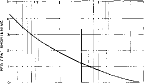 eo 100 200 300 400 600 eoo rooo RATIO OF LENGTH TO DIAMETER 2000 3000 Figure 3 CHART SKOWIMG SHORTENING OF A RESONANT ELEMENT IN TERMS OF RATIO OF LENGTH TO DIAMETER T/ie use of this chart is based on the basic formu/a where radiator length In feet is equal to 468/frequency in Mc. This formula applies to frequencies below perhaps 30 Mc. when the radiator Is made from wire. On higher frequencies, or on 14 and 28 Mc. when the radiator is made af largodiameter tubing, the radiator Is shortened from the value obtained with the above formula by an amount determined by the ratio of length io diameter of the radiator. The amount af this shortening Is obtainable from the chart shown above. shortening can be determined with the aid of the chart of figure 3. In this chart the amount of additional shortening over the values given in the previous paragraph is plotted against the ratio of the length to the diameter of the half-wave radiator. The length of a wave in free space is somewhat longer than the length of an antenna for the same frequency. The actual free-space half-wave length is given by the following expressions: Hedf-wavelength Half-wave length Freq. in Mc. 5905 Freq. in Mc. in feet in inches Harmonic A wire in space can resonate at Resonance more than one frequency. The lowest frequency at which it resonates is cedled its fundamental frequency, and at that frequency it is approximately a half wavelength long. A wire can have two, three, four, five, or more standing waves on it, and thus it resonates at approximately the integral harmonics of its fundamental frequency. However, the higher harmonics are not exactly integral multiples of the lowest resonant frequency as a result of end effects. HANDBOOK Radiation Resistance 407 A harmonic operated antenna is somewhat longer than the corresponding integral number of dipoles, and for this reason, the dipole length formula cannot be used simply by multiplying by the corresponding harmonic. The intermediate half wave sections do not have end effects. Also, the current distribution is disturbed by the fact that power can reach some of the half wave sections only by flowing through other sections, the latter then acting not only as radiators, but also as transmission lines. For the latter reason, the resonant length will be dependent to an extent upon the method of feed, as there will be less attenuation of the current along the antenna if it is fed at or near the centet than if fed towards or at one end. Thus, the antenna would have to be somewhat longer if fed near one end than if fed near the center. The difference would be small, however, unless the antenna were many wavelengths long. The length of a center fed harmonically operated doublet may be found from the formula: (K-.05) X 492 L = - Freq. in Mc. where К = number of waves on antenna L = length in feet Under conditions of severe current attenuation, it is possible for some of the nodes, or loops, actually to be slightly greater than a physical half wavelength apart. Practice has shown that the most practical method of resonating a harmonically operated antenna accurately is by cut and try, or by using a feed system in which both the feed line and antenna are resonated at the station end as an integral system. A dipole or half-wave antenna is said to operate on its fundamental or first harmonic. A full wave antenna, 1 wavelength long, operates on its second harmonic. An antenna with five half-wavelengths on it would be operating on its fifth harmonic. Observe that the fifth harmonic antenna is 2У2 wavelengths long, rjot 5 wavelengths. -Di - Figure 4 EFFECT OF SERIES INDUCTANCE AND CAPACITANCE ON THE LENGTH OF A HALF-WAVE RADIATOR The fop antenna hos been electrically /engfh-ened by placing a coil in series with the center. In other words, on antenna with a lumped inductance in its center can be made shorter for a given frequency than a plain wire radiator. The bottom antenna has been capacitively shortened electrically. In other words, an antenna with a capacitor in series with It must be made longer for a given frequency since ifs effective electrical length as compared to plain wire is shorter. If an antenna is slightly too long, it can be resonated by series insertion of a variable capacitor at a high current point. If it is slightly too short, it can be resonated by means of a variable inductance. These two methods, illustrated schematically in figure 4, are generally employed when part of the antenna is brought into the operating room. With an antenna array, or an antenna fed by means of a transmission line, it is more common to cut the elements to exact resonant length by cut and try procedure. Exact antenna resonance is more important when the antenna system has low radiation resistance; an antenna with low radiation resistance has higher Q (tunes sharper) than an antenna with high radiation resistance. The higher Q does not indicate greater efficiency; it simply indicates a sharper resonance curve. Antenna Most types of antennas operate Resonance most efficiently when tuned or resonated to the frequency of operation. This consideration of course does not apply to the rhombic antenna and to the parasitic elements of arrays employing para-sitically excited elements. However, in practically every other case it will be found that increased efficiency results when the entire antenna system is resonant, whether it be a simple dipole or an elaborate array. The radiation efficiency of a resonant wire is many times that of a wire which is not resonant. 21-3 Radiation Resistance and Feed-Point Impedance In many ways, a half-wave antenna is like a tuned tank circuit. The main difference lies in the fact that the elements of inductance, capacitance, and resistance ate lumped in the tank circuit, and are distributed throughout the length of an antenna. The center of a half-wave radiator is effectively at ground potential as far as r-f voltage is concerned, although the current is highest at that point. о ш о z < I-л UJ СЕ I- г Q ш ш 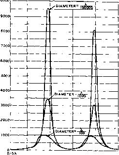 + 8000 0.5Х р.ох i.5X г.ол OVERALL LENGTH OF RADIATOR Figure 5 FEED POfNT RESISTANCE OF A CENTER DRIVEN RADIATOR AS A FUNCTION OF PHYSICAL LENGTH IN TERMS OF FREE SPACE WAVELENGTH When the antenna is resonant, and it always should be for best results, the impedance at the center is substantially resistive, and is termed the radiation resistance. Radiation resistance is a fictitious term; it is that value of resistance (referred to the current loop) which would dissipate the same amount of power as being radiated by the antenna, when fed with the current flowing at the current loop. The radiation resistance depends on the antenna length and its proximity to nearby objects which either absorb or re-radiate power, such as the ground, other wires, etc. The Marconi Before going too far with the Antenna discussion of radiation resist- ance, an explanation of the Marconi (grounded quarter wave) antenna is in order. The Marconi antenna is a special type of Hertz antenna in which the earth acts as the other half of the dipole. In other words, the current flows into the earth instead of into a similar quarter-wave section. Thus, the current loop of a Marconi antenna is at the base rather than in the center. In either case it is a quarter wavelength from the end. A half-wave dipole far from ground and other reflecting objects has a radiation resistance at the center of about 73 ohms. A Marconi an- 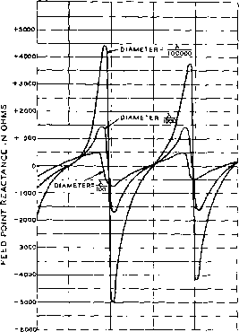 0.I5X о.5л i.ox I.5X г.ох г.5х OVERALL LENGTH OF RADIATOR Figure 6 REACTIVE COMPONENT OF THE FEED POINT IMPEDANCE OF A CENTER DRIVEN RADIATOR AS A FUNCTION OF PHYSICAL LENGTH IN TERMS OF FREE SPACE WAVELENGTH tenna is simply one-half of a dipole. For that reason, the radiation resistance is roughly half the 73-ohm impedance of the dipole or 36.5 ohms. The radiation resistance of a Marconi antenna such as a mobile whip will be lowered by the proximity of the automobile body. Antenna Because the power throughout the Impedance antenna is the same, the impedance of a resonant antenna at any point along its length merely expresses the ratio between voltage and current at that point. Thus, the lowest impedance occurs where the current is highest, namely, at the center of a dipole, or a quarter wave from the end of a Marconi. The impedance rises uniformly toward each end, where it is about 2000 ohms for a dipole remote from ground, and about twice high for a vertical Marconi. If a vertical half-wave antenna is set up so that its lower end is at the ground level, the effect of the ground reflection is to increase HEIGHT IN WAVELENGTHS OF CENTER OF VERTICAL HALF-WAVE ANTENNA ABOVE PERFECT GROUND .25 .3 .4 .5 .8 .7 .75 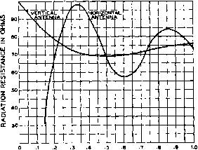 HEIGHT IN WAVELENGTHS OF HORIZONTAL HALF-WAVE ANTENNA ABOVE PERFECT GROUND Figure 7 EFFECT OF HEIGHT ON THE RADIATION RESISTANCE OF A DIPOLE SUSPENDED ABOVE PERFECT GROUND the radiation resistance to approximately 100 ohms. When a horizontal half-wave antenna is used, the tadiation resistance (and, of course, the amount of energy radiated for a given antenna current) depends on the height of the antenna above ground, since the height determines the phase and amplitude of the wave reflected from the ground back to the antenna. Thus the resultant current in the antenna for a given power is a function of antenna height. Center-fed Feed Point Impedance When a linear radiator is series fed at the center, the resistive and reactive components of the driving point impedance are dependent upon both the length and diameter of the radiator in wavelengths. The manner in which the resistive component varies with the physical dimensions of the radiator is illustrated in figure 5. The manner in which the reactive component varies is illustrated in figure 6. Several interesting things will be noted with respect to these curves. The reactive component disappears when the overall physical length is slightly less than any number of half waves long, the differential increasing with conductor diameter. For overall lengths in the vicinity of an odd number of half wavelengths, the center feed point looks to the generator or transmission line like a series-resonant lumped circuit, while for overall lengths in the vicinity of an even number of half wavelengths, it looks like a parallel-resonant or anti-resonant lumped circuit. Both the feed point resistance and the feed point reactance change more slowly with overall radiator length (or with frequency with a fixed length) as the conductor diameter is increased, indicating that the effective Q is lowered as the diameter is increased. However, in view of the fact that the damping tesistance is nearly all radiation resistance rather than loss resistance, the lower Q does not represent lower efficiency. Therefore, the lower Q is desirable, because it permits use of the radiator over a wider frequency range without resorting to means for eliminating the reactive component. Thus, the use of a large diameter conductor makes the overall system less frequency sensitive. If the diameter is made sufficiently large in terms of wavelengths, the Q will be low enough to qualify the radiator as a broad-band antenna. The curves of figure 7 indicate the theoretical center-point radiation resistance of a half-wave antenna for various heights above perfect ground. These values are of importance in matching untuned radio-frequency feeders to the antenna, in order to obtain a good impedance match and an absence of standing waves on the feeders. Ground Losses Above average ground, the actual radiation resistance of a dipole will vary from the exact value of figure 7 since the latter assumes a hypothetical, perfect ground having no loss and perfect reflection. Fortunately, the curves for the radiation resistance over most types of earth will correspond rather closely with those of the chart, except that the radiation resistance for a horizontal dipole does not fall off as rapidly as is indicated for heights below an eighth wavelength. However, with the antenna so close to the ground and the soil in a strong field, much of the radiation resistance is actually represented by ground loss; this means that a good portion of the antenna power is being dissipated in the earth, which, unlike the hypothetical perfect ground, has resistance. In this case, an appteciable portion of the radiation resistance actually is loss resistance. The type of soil also has an effect upon the radiation pattern, especially in the vettical plane, as will be seen later. The radiation resistance of an antenna generally increases with length, although this increase varies up and down about a constantly increasing average. The peaks and dips are caused by the reactance of the antenna, when its length does not allow it to resonate at the operating frequency. Antenna Antennas have a certain loss re-Effieiency sistance as well as a radiation resistance. The loss resistance defines the power lost in the antenna due to ohm- ic resistance of the wire, ground resistance (in the case of a Marconi), corona discharge, and insulator losses. The approximate effective radiation efficiency (expressed as a decimal) is equal to: Nr = Ra/fla+ Kl) where Ra is equal to the radiation resistance and Rl is equal to the effective loss resistance of the antenna. The loss resistance will be of the order of 0.25 ohm for large-diameter tubing conductors such as are most commonly used in multi-element parasitic arrays, and will be of the order of 0.5 to 2.0 ohms for arrays of normal construction using copper wire. When the radiation resistance of an antenna or array is very low, the current at a voltage node will be quite high for a given power. Likewise, the voltage at a current node will be very high. Even with a heavy conductor and excellent insulation, the losses due to the high voltage and current will be appreciable if the radiation resistance is sufficiently low. Usually, it is not considered desirable to use an antenna or array with a radiation resistance of less than approximately 5 ohms unless there is sufficient directivity, compactness, or other advantage to offset the losses resulting from the low radiation resistance. Ground The radiation resistance of a Mar- Resistance coni antenna, especially, should be kept as high as possible. This will reduce the antenna current for a given power, thus minimizing loss resulting from the series resistance offered by the earth connection. The radiation resistance can be kept high by making the Marconi radiator somewhat longer than a quarter wave, and shortening it by series capacitance to an electrical quarter wave. This reduces the current flowing in the earth connection. It also should be removed from ground as much as possible (vertical being ideal). Methods of minimizing the resistance of the earth connection will be found in the discussion of the Marconi antenna. 21-4 Antenna Directivity All practical antennas radiate better in some directions than others. This characteristic is called directivity. The more directive an antenna is, the more it concentrates the radiation in a certain direction, or directions. The more the radiation is concentrated in a certain direction, the greater will be the field strength produced in that direction for a given amount of total radiated power. Thus the use of a directional antenna or array produces the same result in the favored direction as an increase in the power of the transmitter. The increase in radiated power in a certain direction with respect to an antenna in free space as a result of inherent directivity is called the free space directivity power gain or just space directivity gain of the antenna (referred to a hypothetical isotropic radiator which is assumed to radiate equally well in all directions). Because the fictitious isotropic radiator is a purely academic antenna, not physically realizable, it is common practice to use as a reference antenna the simplest ungrounded resonant radiator, the half-wave Hertz, or resonant doublet. As a half-wave doublet has a space directivity gain of 2.15 db over an isotropic radiator, the use of a resonant dipole as the comparison antenna reduces the gain figure of an array by 2.15 db. However, it should be understood that power gain can be expressed with regard to any antenna, just so long as it is specified. As a matter of interest, the directivity of an infinitesimal dipole provides a free space directivity power gain of 1.5 (or 1.76 db) over an isotropic radiator. This means that in the direction of maximum radiation the infinitesimal dipole will produce the same field of strength as an isotropic radiator which is radiating 1.5 times as much total power. A half-wave resonant doublet, because of its different current distribution and significant length, exhibits slightly more free space power gain as a result of directivity than does the infinitesimal dipole, for reasons which will be explained in a later section. The space directivity power gain of a half-wave resonant doublet is 1.63 (or 2.15 db) referred to an isotropic radiator. Horfzontal When choosing and orienting an Directivity antenna system, the radiation patterns of the various common types of antennas should be given careful consideration. The directional characteristics are of still greater importance when a directive antenna array is used. Horizontal directivity is always desirable on any frequency for point-to-point work. However, it is not always attainable with reasonable antenna dimensions on the lower frequencies. Further, when it is attainable, as on the frequencies above perhaps 7 Mc, with reasonable antenna dimensions, operating convenience is greatly furthered if the maximum lobe of the horizontal directivity is controllable. It is for this reason that rotatable antenna arrays have come into such common usage. Considerable horizontal directivity can be used to advantage when: (1) only point-to-point work is necessary, (2) several arrays are available so that directivity may be changed by selecting or reversing antennas, (3) a single rotatable array is in use. Signals follow the 1 ... 37 38 39 40 41 42 43 ... 80 |
||||||||||||||||||||||||||||||||||||
|
© 2026 AutoElektrix.ru
Частичное копирование материалов разрешено при условии активной ссылки |