 |
 |
 |
| Главная Журналы Популярное Audi - почему их так назвали? Как появилась марка Bmw? Откуда появился Lexus? Достижения и устремления Mercedes-Benz Первые модели Chevrolet Электромобиль Nissan Leaf |
Главная » Журналы » Simple coaxial reflectometer 1 ... 38 39 40 41 42 43 44 ... 80 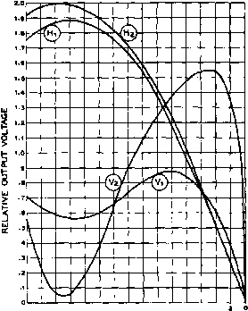 WAVE ANGLE IN DEGREES Figure 8 VERTICAL-PLANE DIRECTIONAL CHARACTERISTICS OF HORIZONTAL AND VER-TICAL DOUBLETS ELEVATED 0.6 WAVELENGTH AND ABOVE TWO TYPES OF GROUND Hi represents о horizontal doublet over typi-cal farmland. H2 over salt water. Vi Is о vertical pattern of rodiotion from a vertical doublet over typical farmland, V2 over salt water. A solt water ground is tbe closest opprooch to on extensive ideally perfect ground that will be met in actual practice. great-circle path, or within 2 or 3 degrees of that path under all normal propagation conditions. However, under turbulent ionosphere conditions, or when unusual propagation conditions exist, the deviation from the great-circle path for greatest signal intensity may be as great as 90°. Making the array rotatable overcomes these difficulties, but arrays having extremely high horizontal directivity become too cumbersome to be rotated, except perhaps when designed for operation on frequencies above 50 Mc. Vertical Vertical directivity is of the great-Directivity est importance in obtaining satisfactory communication above 14 Mc. whether or not horizontal directivity is used. This is true simply because only the energy radiated between certain definite elevct-tion angles is useful for communication. Ener- gy radiated at other elevation angles is lost and performs no useful function. Opfimum Angle The optimum angle of radiation of Rodiotion for propagation of signals between two points is dependent upon a number of variables. Among these significant variables are: (1) height of the ionosphere layer which is providing the reflection, (2) distance between the two stations, (3) number of hops for propagation between the two stations. For communication on the 14-Mc. band it is often possible for different modes of propagation to provide signals between two points. This means, of course, that more than one angle of radiation can be used. If no elevation directivity is being used under this condition of propagation, selective fading will take place because of interference between the waves arriving over the different paths. On the 28-Mc. band it is by far the most common condition that only one mode of propagation will be possible between two points at any one time. This explains, of course, the reason why rapid fading in general and selective fading in particular are almost absent from signals heard on the 28-Mc. band (except for fading caused by local effects). Measurements have shown that the angles useful for communication on the 14-Mc. band are from 3° to about 30°; angles above about 15° being useful only for local work. On the 28-Mc. band measurements have shown that the useful angles range from about 3° to 18°; angles above about 12° being useful only for local (less than 3000 miles) work. These figures assume normal propagation by virtue of the F layer. Angle of Radiation of Typicol Antennos and Arrays It now becomes of interest to determine the a-mount of radiation available at these useful lower angles of radiation from commonly used antennas and antenna arrays. Figure 8 shows relative output voltage plotted against elevation angle (wave angle) in degrees above the horizontal, for horizontal and vertical doublets elevated 0.6 wavelength above two types of ground. It is obvious by inspection of the curves that a horizontal dipole mounted at this height above ground (20 feet on the 28-Mc. band) is radiating only a small amount of energy at angles useful for communication on the 28-Mc. band. Most of the energy is being radiated uselessly upward. The vertical antenna above a good reflecting surface appears much better in this respect-and this fact has been proven many times by actual installations. It might immediately be thought that the a-mount of radiation from a horizontal or vertical 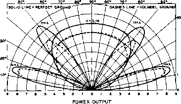 Figure 9 VERTICAL RADIATION PATTERNS Showing the verticol rodiation patterns for half-wave antennas (or colinear half-wave ar extended half-wave antennas) at different heights above average ground and perfect ground. Note that such antennas one-guarter wave obove ground concentrate most radiation ot the very high angles which are useful for communication only on the lower frequency bands. Antennas one-half wave above ground ore nof shown, but the elevation pattern shows one lobe on eoch side at an angle of 30° obove horizontal. dipole could be increased by raising the antenna higher above the ground. This is true to an extent in the case of the horizontal dipole; the low-angle radiation does increase slowly after a height of 0.6 wavelength is reached but at the expense of greatly increased high-angle radiation and the formation of a number of nulls in the elevation pattern. No signal can be transmitted or received at the elevation angles where these nulls have been formed. Tests have shown that a center height of 0.6 wavelength for a vertical dipole (0.35 wavelength to the bottom end) is about optimum for this type of array. Figure 9 shows the effect of placing a horizontal dipole at various heights above ground. It is easily seen by reference to figure 9 (and figure 10 which shows the radiation from a dipole at wave height) that a large percentage of the total radiation from the dipole is being radiated at relatively high angles which are useless for communication on the 14-Mc. and 28-Mc. bands. Thus we see that in order to obtain a worthwhile increase in the ratio of low-angle radiation to high-angle radiation it is necessary to place the antenna high above ground, and in addition it is necessary to use additional means for suppressing high-angle radiation. Suppression of High-angle radiation can be High-ongle suppressed, and this radiation Radiation can be added to that going out at low angles, only through the use of some sort of directive antenna system. There are three general types of antenna arrays composed of dipole elements commonly used which concentrate radiation at the lower more effective angles for high-frequency communication. These types are: (1) The close-spaced out-of-phase system as exemplified by the flat-top beam or W8JK array. Such configurations are classified as end fire arrays. (2) The wide-spaced in-phase arrays, as exemplified by the Lazy H antenna. These configurations are classified as broadside arrays. (3) The close-spaced parasitic systems, as exemplified by the three element rotary beam. A comparison between the radiation from a dipole, a flat-top beam and a pair of dipoles stacked one above the other (half of a lazy H ), in each case with the top of the antenna at a height of % wavelength is shown in figure 11. The improvement in the amplitude of low- 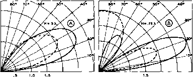 2.0 Z.S 3.0 .3 1.0 GAIN IN FIELD STRENGTH 2.0 2.S 3.0 Figure 10 VERTICAL RADIATION PATTERNS Showing verticol-p/one radiation patterns of a horizontal single-section flat-top beam with one-eighth wave spacing (solid curves) and о horizontal half-wave antenna (dashed curves) when bath are 0.5 wavelength (A) and 0,75 wavelength (B) a-bove ground. Figure 11 COMPARATIVE VERTICAL RADIATION PATTERNS Showing rhe vertical rodiotion patterns of a horizontal single-section flat-top beam (A), on orroy of two stacked horizontal in-phase half-wove elements- half of о Lazy H -(B), and a horizontal dipole (C). In each case the top of tbe antenna system is 0.75 wavelength above ground, as shown ta tbe left of tbe curves. 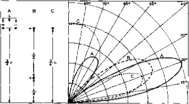 л 1.0 1.5 2.0 2.5 3.0 angle radiation at the expense of the useless high-angle radiation with these simple arrays as contrasted to the dipole is quite marked. Figure 12 compares the patterns of a 3 element beam and a dipole radiator at a height of 0.75 wavelength. It will be noticed that although there is more energy in the lobe of the beam as compared to the dipole, the axis of the beam is at the same angle above the horizontal. Thus, although more radiated energy is provided by the beam at low angles, the average angle of radiation of the beam is no lower than the average angle of radiation of the dipole. 21-6 Propagation of Radio Waves The preceding sections have discussed the manner in which an electromagnetic-wave or radio-wave field may be set up by a radiating system. However, for this field to be useful for communication it must be propagated to some distant point where it may be received, or where it may be reflected so that it may be received at some other point. Radio waves may be propagated to a remote point by either or both of two general methods. Propagation 21-5 Bandwidth The bandwidth of an antenna or an antenna array is a function primarily of the radiation resistance and of the shape of the conductors which make up the antenna system. For arrays of essentially similar construction the bandwidth (or the deviation in frequency which the system can handle without mismatch) is increased with increasing radiation resistance, and the bandwidth is increased with the use of conductors of larger diameter (smaller ratio of length to diameter). This is to say that if an array of any type is constructed of large diameter tubing or spaced wires, its bandwidth will be greater than that of a similar array constructed of single wires. The radiation resistance of antenna arrays of the types mentioned in the previous paragraphs may be increased through the use of wider spacing between elements. With increased radiation resistance in such arrays the radiation efficiency increases since the ohmic losses within the conductors become a smaller percentage of the radiation resistance, and the bandwidth is increased proportionately. 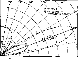 1.0 I.S 2.0 2.5 3.0 3.5 4, GAIN IN FIELD STRENGTH Figure 12 VERTICAL RADIATION PATTERNS Showing vertical radiation patterns of a horizontal dipole (A) and о horizontal 3-element parasitic array (B) at a height above ground of 0.75 wavelength. Note that the axis of tbe main radiation lobes are at the same angle above the horizontal. Note also the suppression of high angle radiation by the parasitic array. 01ЯЕСТ WAVE 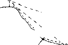 x ©COUND-HEFLECTE ~-\ WAVE ©SURFACE WAVE Figure 13 GROUND-WAVE SIGNAL PROPAGATION The illustration above shows the three components of the ground wave: (A), the surface wave; (B), the direct wave; and (C), the ground-reflected wave. The direct wove and the ground-reflected wove combine at the receiving antenna to make up the space wave. may take place as a result of the ground tvave, or as a result of the sky wave or ionospheric wave. The Ground Wove The term ground wave actually includes several different types of waves which usually are called: (1) the surface wave, (2) the direct wave, and (3) the ground-reflected wave. The latter two waves combine at the receiving antenna to form the resultant wave or the space wave. The distinguishing characteristic of the components of the ground wave is that all travel along or over the surface of the earth, so that they are affected by the conductivity and terrain of the earths surface. The Ionospheric Wove Intense bombardment of or Sky Wove the upper regions of the atmosphere by radiations from the sun results in the formation of ionized layers. These ionized layers, which form the ionosphere, have the capability of reflecting or refracting radio waves which impinge upon them. A radio wave which has been propagated as a result of one or more reflections from the ionosphere is known as an ionospheric wave or a sky wave. Such waves make possible long distance radio communication. Propagation of radio signals by ionospheric waves is discussed in detail in Section 21-8. 21-7 Ground-Wave Communication As stated in the preceding paragraph, the term ground wave applies both to the surface wave and to the space wave (the resultant wave from the combination of the direct wave and the ground-reflected wave) or to a com- bination of the two. The three waves which may combine to make up the ground wave are illustrated in figure 13. The Surfoce Wave The surface wave is that wave which we normally receive from a standard broadcast station. It travels directly along the ground and terminates on the earths surface. Since the earth is a relatively poor conductor, the surface wave is attenuated quite rapidly. The surface wave is attenuated less rapidly as it passes over sea water, and the attenuation decreases for a specific distance as the frequency is decreased. The rate of attenuation with distance becomes so large as the frequency is increased above about 3 Mc. that the surface wave becomes of little value for communication. The Space Wove The resultant wave or space wave is illustrated in figure 13 by the combination of (B) and (C). It is this wave path, which consists of the combination of the direct wave and the ground-reflected wave at the receiving antenna, which is the normal path of signal propagation for line-of-sight or near line-of-sight communication or FM and TV reception on frequencies above about 40 Mc. Below line-of-sight over plane earth or water, when the signal source is effectively at the horizon, the ground-reflected wave does not exist, so that the direct wave is the only component which goes to make up the space wave. But when both the signal source and the receiving antenna are elevated with respect to the intervening terrain, the ground-reflected wave is present and adds vectorially to the direct wave at the receiving antenna. The vectorial addition of the two waves, which travel over different path lengths (since one of the waves has been reflected from the ground) results in an interference pattern. The interference between the two waves brings about a cyclic variation in signal strength as the receiving antenna is raised above the ground. This effect is illustrated in figure 14. From this figure it can be seen that best space-wave reception of a v-h-f signal often will be obtained with the receiving antenna quite close to the ground. This subject, along with other aspects of v-h-f signal propagation and reception, are discussed in considerable detail in a book on fringe-area TV reception.* The distance from an elevated point to the geometrical horizon is given by the approximate equation: d = 1.22\/F wherethe distance * Better TV Reception, by W. W, Smith and R. L. Daw-ley, published by Editors and Engineers, Ltd., Summer-land, Coiif. HANDBOOK Ground Wave Communication 415 TRANSMITTING ANTENNA DIRECT WAVES 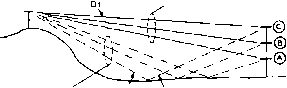 GROUND-REFLECTED WAVES RECEIVING ANTENNA AT DIFFERENT HEIGHTS Figure 14 WAVE INTERFERENCE WITH HEIGHT When fhe source of о horizontaltypolorized space-wave signol is obove the horizeri, the received signal at a distant location will go rhrough о cyclic variation as the antenna height is progressively raised. This is due to the difference in total path length between the direct wave ond fhe ground-reflected wave, and to the fact that this path length difference changes with antenna height. When the path length difference is such thot the two waves arrive ot the receiving antenna with a phase difference of 360° or some multiple of 360°, the two waves will appear to be in phase as for as the antenna is concerned and maximum signal will be obtained. On fhe other hand, when the onfenno height is such that the path length difference for the two waves causes the waves to arrive with a phase difference of an odd multiple of 180° the two waves will substontiolly cancel, and a null will be obfornecf of fhaf antenna height. The difference between Dj anrf D2 plus D3 is the path-length difference. Nate also that there is an additional 180 phase shift in the ground-reflected wave at the point where it is reflected from fhe ground. It is this latter phose shift which causes the space-wave field intensify of a horizontally polarized wave to be zero with the receiving antenna at ground level. d is in miles and the antenna height H is in feet. This equation must be applied separately to the transmitting and receiving antennas and the results added. However, refraction and diffraction of the signal around the spherical earth cause a smaller reduction in field strength than would occur in the absence of such bending, so that the average radio horizon is somewhat beyond the geometrical horizon. The equation = 1.4 \pR is sometimes used for determining the radio horizon. Tropospheric Propagation by signal bending Propagation in the lower atmosphere, called twpospheric propagation, can result in the reception of signals over a much greater distance than would be the case if the lower atmosphere were homogeneous. In a homogeneous or well-mixed lower atmosphere, called a normal or standurd atmosphere, there is a gradual and uniform decrease in index of refraction with height. This effect is due to the combined effects of a decrease in temperature, pressure, and water-vapor content with height. This gradual decrease in refractive index with height causes waves radiated at very low angles with respect to the horizontal to be bent downward slightly in a curved path. The result of this effect is that such waves will be propagated beyond the Ггие or geometrical horizon. In a so-called standard atmosphere the effect of the curved path is the same as though the radius of the earth were increased by approximately one third. This condition extends the horizon by approximately 30 per cent for normal propagation, and the extended-horizon is known as the radio path horizon, mentioned before. Conditions Leading to When the temperature, Tropospheric pressure, or water-vapor Stratification content of the atmos- phere does not change smoothly with rising altitude, the discontinuity or stratification will result in the reflection or refraction of incident v-h-f signals. Ordinarily this condition is more prevalent at night and in the summer. In certain areas, such as along the west coast of North America, it is frequent enough to be considered normal. Signal strength decreases slowly with distance and, if the favorable condition in the lower atmosphere covers sufficient area, the range is limited only by the transmitter power, antenna gain, receiver sensitivity, and signal-to-noise ratio. There is no skip distance. Usually, transmission due to this condition is accompanied by slow fading, although fading can be violent at a point where direct waves of about the same strength are also received. Bending in the troposphere, which refers to the region from the earths surface up to about 10 kilometers, is more likely to occur on days when there are stratus clouds than on clear, cool days with a deep blue sky. The temperature or humidity discontinuities may be broken up by vertical convection currents over land in the daytime but are more likely to continue during the day over water. This condition is in some degree predictable from weather information several days in advance. It does not depend on the sunspot cycle. Like direct communication, best results require similar antenna polarization or orientation at both the transmitting and receiving ends, whereas in transmission via reflection in the ionosphere (that part of the atmosphere between about 50 and 500 kilometers high) it makes little difference whether antennas are similarly polarized. Duct Formation When bending conditions are particularly favorable they Y ®/ 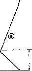 INVERSION ANO DUCT REFRACTIVE INDEX Figure 15 ILLUSTRATING DUCT TYPES Showing two types of variation in refractive index with height which will give rise to the formation of a duct. An elevated duct is shown ot (A), and a ground-based duct is shown at (B). Such ducts can propagate grounc/-wove signals far beyond their normal range. may give rise to the formation of a duct which can propagate waves with very little attenuation over great distances in a manner similar to the propagation of waves through a wave guide. Guided propagation through a duct in the atmosphere can give quite remarkable transmission conditions (figure 15). However, such ducts usually are formed only on an over-water path. The depth of the duct over the waters surface may be only 20 to 50 feet, or it may be 1000 feet deep or more. Ducts exhibit a low-frequency cutoff characteristic similar to a wave guide. The cutoff frequency is determined by depth of the duct and by the strength of the discontinuity in refractive index at the upper surface of the duct. The lowest frequency that can be propagated by such a duct seldom goes below 50 Mc, and usually will be greater than 100 Mc. even along the Pacific Coast. Stratospheric Communication by virtue of Reflection stratospheric reflection can be brought about during magnetic storms, aurora borealis displays, and during meteor showers. Dx communication during extensive meteor showers is characterized by frequent bursts of great signal strength followed by a rapid decline in strength of the received signal. The motion of the meteor forms an ionized trail of considerable extent which can bring about effective reflection of signals. However, the ionized region persists only for a matter of seconds so that a shower of meteors is necessary before communication becomes possible. The type of communication which is possible during visible displays of the aurora borealis and during magnetic storms has been called auroratype dx. These conditions reach a maximum somewhat after the sunspot cycle peak, possibly because the spots on the sun are nearer to its equator (and more directly in line with the earth) in the latter part of the cycle. Ionospheric storms generally accompany magnetic storms. The normal layers of the ionosphere may be churned or broken up, making radio transmission over long distances difficult or impossible on high frequencies. Unusual conditions in the ionosphere sometimes modulate v-h-f waves so that a definite tone or noise modulation is noticed even on transmitters located only a few miles away. A pecularity of this type of auroral propagation of v-h-f signals in the northern hemisphere is that directional antennas usually must be pointed in a northerly direction for best results for transmission or reception, regardless of the direction of the other station being contacted. Distances out to 700 or 800 miles have been covered during magnetic storms, using 30 and 50 Mc. transmitters, with little evidence of any silent zone between the stations communicating with each other. Generally, voice-modulated transmissions are difficult or impossible due to the tone or noise modulation on the signal. Most of the communication of this type has taken place by c.w. or by tone modulated waves with a keyed carrier. 21-8 Ionospheric Propagation Propagation of radio waves for communication on frequencies between perhaps 3 and 30 Mc is normally carried out by virtue of ionospheric reflection or refraction. Under conditions of abnormally high ionization in the ionosphere, communication has been known to have taken place by ionospheric reflection on frequencies higher than 50 Mc. The ionosphere consists of layers of ionized gas located above the stratosphere, and extending up to possibly 300 miles above the earth. Thus we see that high-frequency radio waves may travel over short distances in a direct line from the transmitter to the receiver, or they can be radiated upward into the ionosphere to be bent downward in an indirect ray, returning to earth at considerable distance from the transmitter. The wave reaching a receiver via the ionosphere route is termed a sky wave. The wave reaching a receiver by traveling in a direct line from the transmitting antenna to the receiving antenna is commonly called a ground wave. The amount of bending at the ionosphere 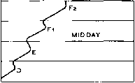 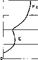 MIDNIGHT IONIZATION DENSITY Figure 16 IONIZATION DENSITY IN THE IONOSPHERE Showing typicai ionization cfensity of the ionosphere in mid-summer. Note thot the Fj and D layers disappear at night, and that the density of the E layer falls to such a low value that it is ineffective. which the sky wave can undergo depends upon its frequency, and the amount of ionization in the ionosphere, which is in turn dependent upon radiation from the sun. The sun increases the density of the ionosphere layers (figure 16) and lowers their effective height. For this reason, the ionosphere acts very differently at different times of day, and at different times of the year. The higher the frequency of a radio wave, the farther it penetrates the ionosphere, and the less it tends to be bent back toward the earth. The lower the frequency, the more easily the waves are bent, and the less they penetrate the ionosphere. l60-meter and 80-meter signals will usually be bent back to earth even when sent straight up, and may be considered as being reflected rather than refracted. As the frequency is raised beyond about 5,000 kc. (dependent upon the critical frequency of the ionosphere at the moment), it is found that waves transmitted at angles higher than a certain critical angle never return to earth. Thus, on the higher frequencies, it is necessary to confine radiation to low angles, since the high angle waves simply penetrate the ionosphere and are lost. The Fj Layer The higher of the two major reflection regions of the ionosphere is called the Рг layer. This layer has a virtual height of approximately 175 miles at night, and in the daytime it splits up into two layers, the upper one being called the Fj layer and the lower being called the layer. The height of the Fj layer during daylight hours is normally about 250 miles on the average and the F, layer often has a height of as low as 140 miles. It is the Fj layer which supports all nighttime dx communication and nearly all daytime dx propagation. The E Layer Below the F layer is another layer, called the Б layer, which is of importance in daytime communication over moderate distances in the frequency range between 3 and 8 Mc. This layer has an almost constant height at about 70 miles. Since the re-combination time of the ions at this height is rather short, the Б layer disappears almost completely a short time after local sunset. The D Layer Below the E layer at a height of about 35 miles is an absorbing layer, called the D layer, which exists in the middle of the day in the summertime. The layer also exists during midday in the winter time during periods of high solar activity, but the layer disappears completely at night. It is this layer which causes high absorption of signals in the medium and high-frequency range during the middle of the day. Critical Frequency The critical frequency of an ionospheric layer is the highest frequency which will be reflected when the wave strikes the layer at vertical incidence. The critical frequency of the most highly ionized layer of the ionosphere may be as low as 2 Mc. at night and as high as 12 to 13 Mc. in the middle of the day. The critical frequency is directly of interest in that a skip-distance zone will exist on all frequencies greater than the highest critical frequency at that time. The critical frequency is a measure of the density of ionization of the reflecting layers. The higher the critical frequency the greater the density of ionization. Moximum Usable Frequency The maximum usable frequency or m.u.f. is of great importance in long-distance communication since this frequency is the highest that can be used for communication between any two specified areas. The m.u.f. is the highest frequency at which a wave projected into space in a certain direction will be returned to earth in a specified region by ionospheric reflection. The m.u.f. is highest at noon or in the early afternoon and is highest in periods of greatest sunspot activity, often going to frequencies higher than 50 Mc. (figure 17). 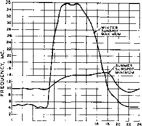 e 10 12 14 LOCAL TIME Figure 17 TYPICAL CURVES SHOWING CHANGE IN M.U.F. AT MAXIMUM AND MINIMUM POINTS IN SUNSPOT CYCLE The m.u.f. often drops to frequencies below 10 Mc. in the early morning hours. The high m.u.f. in the middle of the day is brought about by reflection from the Fj layer. M.u.f. data is published periodically in the magazines devoted to amateur work, and the m.u.f. can be calculated with the aid of Basic Radio Propagation Predictions, CRPL-D, published monthly by the Government Printing Office, Washington, D.C. Absorption ond Optimum Working Frequency The optimum working frequency for any particular direction and distance is usually about 15 per cent less than the m.u.f. for contact with that particular location. The absorption by the ionosphere becomes greater and greater as the operating frequency is progressively lowered below the m.u.f. It is this condition which causes signals to increase tremendously in strength on the 14-Mc. and 28-Mc. bands just before the signals drop completely out. At the time when the signals are greatest in amplitude the operating frequency is equal to the m.u.f. Then as the signals drop out the m.u.f. has become lower than the operating frequency. Skip Distance The shortest distance from a transmitting location at which signals reflected from the ionosphere can be returned to the earth is called the skip distance. As was mentioned above under Critical Frequency there is no skip distance for a frequency below the critical frequency of the most highly ionized layer of the ionosphere at the time of transmission. However, the skip distance is always present on the 14-Mc. band and is almost always present on the 3.5-Mc. and 7-Mc. bands at night. The actual measure of the skip distance is the distance between the point where the ground wave falls to zero and the point where the sky wave begins to return to earth. This distance may vary from 40 to 50 miles on the 3.5-Mc. band to thousands of miles on the 28-Mc. band. The Sporadic-E Occasional patches of ex-Layer tremely high ionization density appear at intervals throughout the year at a height approximately equal to that of the Б layer. These patches, called the sporadic-E layer may be very small or may be up to several hundred miles in extent. The critical frequency of the sporadic-E layer may be greater than twice that of the normal ionosphere layers which exist at the same time. It is this sporadic-E condition which provides short-skip contacts from 400 to perhaps 1200 miles on the 28-Mc. band in the evening. It is also the sporadic-E condition which provides the more common type of band opening experienced on the 50-Mc. band when very loud signals are received from stations from 400 to 1200 miles distant. Cycles in Ionosphere Activity The ionization density of the ionosphere is determined by the amount of radiation (probably ultra violet) which is being received from the sun. Consequently, ionosphere activity is a function of the amount of radiation of the proper character being emitted by the sun and is also a function of the relative aspect of the regions in the vicinity of the location under discussion to the sun. There are four main cycles in ionosphere activity. These cycles are: the daily cycle which is brought about by the rotation of the earth, the 27-day cycle which is caused by the rotation of the sun,the seasonal cycle which is caused by the movement of the earth in its orbit, and the ll-year cycle which is a cycle in sunspot activity. The effects of these cycles are superimposed insofar as ionosphere activity is concerned. Also, the cycles are subject to short term variations as a result of magnetic storms and similar terrestrial disturbances. The most recent minimum of the 11-year sunspot cycle occured during the winter of 1954-1955, and we are currently moving up the slope of a new cycle, the maximum of which will probably occur during the year 1958. The current cycle is pictured in figure 18. Fading The lower the angle of radiation of the wave, with respect to the hori- HANDBOOK 11-Year Sunspot Cycle 419 dc i I tfl 5 i Э (-о □l d 1л Q Ы I o о 1Л
46 50 52 YEAR Figure 18 THE YEARLY TREND OF THE ll-YEAR SUNSPOT CYCLE. RADIO CONDITIONS IN GENERAL WILL IMPROVE DURING 1955-1958 AS THE CYCLE ADVANCES 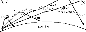 THANSMITTEB Figure 19 lONOSPHERE-REFLECTION WAVE PATHS Showing typicol ionosphere-reflection wave paths during daylight hours when ionization density is such that frequencies as high as 28 Mc, will be returned to earth. The distance between ground-wave ronge and that range where the ionosphere-reflected wave of о specific frequency first will be returned to earth is called the skip distance. zon, the farther away will the wave return to earth, and the greater the skip distance. The wave can be reflected back up into the ionosphere by the earth, and then be reflected back down again, causing a second skip distance area. The drawing of figure 19 shows the multiple reflections possible. When the receiver receives signals which have traveled over more than one path between transmitter and receiver, the signal impulses will not all arrive at the same instant, as they do not all travel the same distance. When two or more signals arrive in the same phase at the receiving antenna, the resulting signal in the receiver will be quite strong. On the other hand, if the signals arrive 180 out of phase, so they tend to cancel each other, the received signal will drop-perhaps to zero if perfect cancellation occurs. This explains why high-frequency signals are subject to fading. Fading can be greatly reduced on the high frequencies by using a transmitting antenna with sharp vertical directivity, thus cutting down the number of possible paths of signal arrival. A receiving antetma with similar characteristics (sharp vertical directivity) will further reduce fading. It is desirable, when using antennas with зЬаф vertical directivity, to use the lowest vertical angle consistent with good signal strength for the frequency used. Scottered Scattered reflections are random. Reflections diffused, substantially isotropic reflections which are partly re- sponsible for reception within the skip zone, and for reception of signals from directions off the great circle path. In a heavy fog or mist, it is difficult to see the road at night because of thebright glare caused by scattered reflection of the headlight beam by the minute droplets. In fact, the road directly to the side of the car will be weakly illuminated under these conditions, whereas it would not on a clear night (assuming flat, open coimtry). This is a good example of propagation of waves by scattered reflections into a zone which otherwise would not be illuminated. Scattering occurs in the ionosphere at all times, because of irregularities in the medium (which result in patches* corresponding to the water droplets) and because of random-phase radiation due to the collision or recombination of free electrons. However, the nature of the scattering varies widely with time, in a random fashion. Scattering is particularly prevalent in the E region, but scattered reflections may occur at any height, even well out beyond the virtual height of the layer. There is no critical frequency or lowest perforating frequency involved in the scattering mechanism, though the intensity of the scattered reflections due to typical scattering in the E region of the ionosphere decreases with frequency. When the received signal is due primarily to scattered reflections, as is the case in the skip zone or where the great circle path does not provide a direct sky wave (due to low critical or perforation frequency, or to an ionosphere storm) very bad distortion will be evi- dent, particularly a flutter fade and a characteristic hollow or echo effect. Deviations from a great circle path are especially noticeable in the case of great circle paths which cross or pass near the auroral zones, because in such cases there often is complete or nearly complete absorption of the direct sky wave, leaving off-path scattered reflections the only mechanism of propagation. Under such conditions the predominant wave will appear to arrive from a direction closer to the equator, and the signal will be noticeably if not considerably weaker than a direct sky wave which is received under favorable conditions. Irregular reflection of radio waves from scattering patches is divided into two categories: short scatter and long scatter . Short scatter is the scattering that occurs when a radio wave first reaches the scattering patches or media. Ordinarily it is of no particular benefit, as in most cases it only serves to fill in the inner portion of the skip zone with a weak, distorted signal. Long scatter occurs when a wave has been refracted from the Fj layer and strikes scattering patches or media on the way down. When the skip distance exceeds several hundred miles, long scatter is primarily responsible for reception within the skip zone, particularly the outer portion of the skip zone. Distortion is much less severe than in the case of short scatter, and while the signal is likewise weak, it sometimes can be utilized for satisfactory communication. During a severe ionosphere disturbance in the north auroral zone, it sometimes is possible to maintain communication between the Eastern United States and Northern Europe by the following mechanism: That portion of the energy which is radiated in the direction of the great circle path is completely absorbed upon reaching the auroral zone. However, the portion of the wave leaving the United States in a southeasterly direction is refracted downward from the Fj layer and encounters scattering patches or media on its downward trip at a distance of approximately 2000 miles from the transmitter. There it is reflected by long scatter in all directions, this scattering region acting like an isotropic radiator fed with a very small fraction of the original transmitter power. The great circle path from this southerly point to northern Europe does not encounter unfavorable ionosphere conditions, and the wave is propagated the rest of the trip as though it had been radiated from the scattering region. Another type of scatter is produced when a sky wave strikes certain areas of the earth. Upon striking a comparatively smooth surface such as the sea, there is little scattering, the wave being shot up again by what could be considered specular or mirror reflection. But upon striking к mountain range, for instance, the retadiation or reflected energy is scattered, some of it being directed back towards the transmitter, thus providing another mechanism for producing a signal within the skip zone. Meteors and When a meteor strikes the earths Bursts atmosphere, a cylindrical region of free electrons is formed at proximately the height of the E layer. This slender ionized column is quite long, and when first formed is sufficiently dense to reflect radio waves back to earth most readily, including v-h-f waves which are not ordinarily returned by the Fj layer. The effect of a single meteor, of normal size, shows up as a sudden burst of signal of short duration at points not ordinarily reached by the transmitter. After a period of from 10 to 40 seconds, recombination and diffusion have progressed to the point where the effect of a single fairly large meteor is not perceptible. However, there are many small meteors impinging upon earths atmosphere every minute, and the aggregate effect of their transient ionized trails, including the small amount of residual ionization that exists for several minutes after the original flash but is too weak and dispersed to prolong a burst , is believed to contribute to the existence of the nighttime E layer, and perhaps also to sporadic E patches. While there are many of these very small meteors striking the earths atmosphere every minute, meteors of normal size (sufficiently large to produce individual bursts ) do not strike nearly so frequently except during some of the comparatively rare meteor showers . During one of these displays a quivering ionized layer is produced which is intense enough to return signals in the lower v-h-f range with good strength, but with a type of flutter distortion which is characteristic of this type of propagation. 21-9 Transmission Lines For many reasons it is desirable to place an antenna or radiating system as high and in the clear as is physically possible, utilizing some form of nonradiating transmission line to carry energy with as little loss as possible from the transmitter to the radiating antenna, and conversely from the antenna to the receiver. There are many different types of transmission lines and, generally speaking, practically any type of transmission line or feeder system may be used with any type of antenna. How- 1 ... 38 39 40 41 42 43 44 ... 80 |
||||||||||||||||||||||||||||||||||||||||||||||||||||||||||||||||||||||||||||||||||||||||||||||||||||||||||||||||||||||||||||||||||||||||||||||||||||||||||||||||||||||||||||||||||||||||||||||||||||||||||||||||||||||||||||||||||||||||||||||||||||||||||||||||||||||||||||||||||||||||||||||||||||||||||||
|
© 2026 AutoElektrix.ru
Частичное копирование материалов разрешено при условии активной ссылки |