 |
 |
 |
| Главная Журналы Популярное Audi - почему их так назвали? Как появилась марка Bmw? Откуда появился Lexus? Достижения и устремления Mercedes-Benz Первые модели Chevrolet Электромобиль Nissan Leaf |
Главная » Журналы » Simple coaxial reflectometer 1 ... 39 40 41 42 43 44 45 ... 80 ever, mechanical or electrical considerations often make one type of transmission line better adapted for use to feed a particular type of antenna than any other type. Transmission lines for carrying r-f energy are of two general types: non-resonant and resonant. A non-resonant transmission line is one on which a successful effort has been made to eliminate reflections from the termination (the antenna in the transmitting case and the receiver for a receiving antenna) and hence one on which standing waves do not exist or are relatively small in magnitude. A resonant line, on the other hand, is a transmission line on which standing waves of appreciable magnitude do appear, either through inability to match the characteristic impedance of the line to the termination or through intentional design. The principal types of transmission line in use or available at this time include the open-wire line (two-wire and four-wire types), two-wire solid-dielectric line ( Twin-Lead and similar ribbon or tubular types), two-wire polyethylene-filled shielded line, coaxial line of the solid-dielectric, beaded, stub-supported, or pressurized type, rectangular and cylindrical wave guide, and the single-wire feeder operated against ground. The significant characteristics of the more popular types of transmission line available at this time are given in the chart of figure 21. 21-10 Non-Resonont Transmission Lines A non-resonant or untuned transmission line is a line with negligible standing waves. Hence, a non-resonant line is a line carrying r-f power only in one direction-from the source of energy to the load. Physically, the line itself should be identical throughout its length. There will be a smooth distribution of voltage and current throughout its length, both tapering off very slightly towards the load end of the line as a result of line losses. The attenuation (loss) in certain types of untuned lines can be kept very low for line lengths up to several thousand feet. In other types, particularly where the dielectric is not air (such as in the twistedpair line), the losses may become excessive at the higher frequencies, unless the line is relatively short. Transmission-Line Impedance All transmission lines have distributed inductance, capacitance and resistance. Neglecting the resistance, as it is of minor importance in short lines, it is found 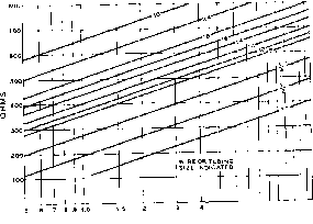 J 6 7 в 9 10 12 li NCHES. CENTER TO CENTER Figure 20 CHARACTERISTIC IMPEDANCE OF TYPICAL TWO-WIRE OPEN LINES that the inductance and capacitance per unit length determine the characteristic or surge impedance of the line. Thus, the surge impedance depends upon the nature and spacing of the conductors, and the dielectric separating them. Speaking in electrical terms, the characteristic impedance of a transmission line is simply the ratio of the voltage across the line to the current which is flowing, the same as is the case with a simple resistor: Zg = E/l. Also, in a substantially loss-less line (one whose attenuation per wavelength is small) the energy stored in the line will be equally divided between the capacitive field and the inductive field which serve to propagate the energy along the line. Hence the characteristic impedance of a line maybe expressed as: Vl/c. Two-Wire A two-wire transmission system Open Line is easy to construct. Its surge impedance can be calculated quite easily, and when properly adjusted and balanced to ground, with a conductor spacing which is negligible in terms of the wavelength of the signal carried, undesirable feeder radiation is minimized; the current flow in the adjacent wires is in opposite directions, and the magnetic fields of the two wires are in opposition to each other. When a two-wire line is terminated with the equivalent of a pure resistance equal to the characteristic impedance of the line, the line becomes a non-resonant line. Expressed in physical terms, the characteristic impedance of a two-wire open line is equal to: CHARACTERISTICS OF COMMON TRANSMISSION LINES
9 approximate. exact figure varies slightly with manufacturer. FIGURE 21 Z = 276 log Where: S is the exact distance between wire centers in some convenient unit of measurement, and d is the diameter of the wire measured in the same units as the wire spacing, S. Since- expresses a ratio only, the units of measurement may be centimeters, millimeters, or inches. This makes no difference in the answer, so long as the substituted values for S and d are in the same units. The equation is accurate so long as the wire spacing is relatively large as compared to the wire diameter. Surge impedance values of less than 200 ohms are seldom used in the open-type two-wire line, and, even at this rather high value of Zp the wire spacing S is uncomfortably close, being only 5.3 times the wire diameter d. Figure 20 gives in graphical form the surge impedance of practicable two-wire lines. The chart is self-explanatory, and is sufficiently accurate for practical purposes. Ribbon and Instead of using spacer in- Tubular Trans- sulators placed periodically mission Line along the transmission line it is possible to mold the line conductors into a ribbon or tube of flexible low-loss dielectric material. Such line, with polyethylene dielectric, is used in enormous quantities as the lead-in transmission line for FM and TV receivers. The line is available from several manufacturers in the ribbon and tubular configuration, with characteristic impedance values from 75 to 300 ohms. Receiving types, and transmitring types for power levels up to one IcHowatt in the h-f range, are listed with their pertinent characteristics, in the table of figure 21. Coaxial Line Several types of coaxial cable have come into wide use for feeding power to an antenna system. A cross-sectional view of a coaxial cable (sometimes called concentric cable or line) is shown in figure 22. As in the parallel-wire line, the power lost in a properly terminated coaxial line is the sum of the effective resistance losses along the length of the cable and the dielectric losses between the two conductors. Of the two losses, the effective resistance loss is the greater; since it is largely due to the skin effect, the line loss (all other conditions the same) will increase directly as the square root of the frequency. Figure 22 shows that, instead of having two conductors running side by side, one of the conductors is placed inside of the other. Since the outside conductor completely shields the inner one, no radiation takes place. The conductors may both be tubes, one within the other; the line may consist of a solid wire within a tube, or it may consist of a stranded or solid inner conductor with the outer conductor made up of one or two wraps of copper shielding braid. In the type of cable most popular for military and non-commercial use the inner conductor consists of a heavy stranded wire, the outer conductor consists of a braid of copper wire, and the inner conductor is supported within the outer by means of a semi-solid dielectric of exceedingly low loss characteristics called polyethylene. The Army-Navy designation on one size of this cable suitable for power levels up to one kilowatt at frequencies as high as 30 Mc. is AN/RG-8/U. The outside diameter of this type of cable is approximately one-half inch. The characteristic impedance of this cable type is 52 ohms, but other similar types of greater and smaller power-handling capacity are available in impedances of 52, 75, and 95 ohms. When using solid dielectric coaxial cable it is necessary that precautions be taken to insure that moisture cannot enter the line. If the better grade of connectors manufactured for the line are employed as terminations, this condition is automatically satisfied. If connectors are not used, it is necessary that some type of moisture-proof sealing compound be applied to the end of the cable where it will be exposed to the weather. Nearby metallic objects cause no loss, and coaxial cable may be run up air ducts or ele- о ш и 70 dc ш I- Ч cc < I о
Zo= 138 LO<:,o COAXIAL OH CONCENTRIC LINE  D(=INSIOE DIAMETER OF OUTER CONDUCTOR D=0UTSI0E DIAMETER OF INNER CONDUCTOR 2.36 1 3.21 RATIO OF DIAMETERS Figure 22 CHARACTERISTIC IMPEDANCE OF AIR-FILLED COAXIAL LINES If tbe /il/ing of fbe line is a dielectric ma-ferial other than air, the characteristic impedance of the line will be reduced by a factor proportional fo fhe square-root of fhe dielectric constant of the material used as a dielectric within the line. vator shafts, inside walls, or through metal conduit. Insulation troubles can be forgotten. The coaxial cable may be buried in the ground or suspended above ground. Standing Waves Standing waves on a transmission line always are the result of the reflection of energy. The only significant reflection which takes place in a normal installation is that at the load end of the line. But reflection can take place from discontinuities in the line, such as caused by insulators, bends, or metallic objects adjacent to an unshielded line. When a uniform transmission line is terminated in an impedance equal to its surge impedance, reflection of energy does not occur, and no standing waves are present. When the load termination is exactly the same as the line impedance, it simply means that the load takes energy from the line just as fast as the line delivers it, no slower and no faster. Thus, for proper operation of an untuned line (with standing waves eliminated), some form of impedance-matching arrangement must be used between the transmission line and the antenna, so that the radiation resistance of the antenna is reflected back into the line as a nonreactive impedance equal to the line impedance. The termination at the antenna end is the only critical characteristic about the untuned line fed by a transmitter. It is the reflection from the antenna end which starts waves moving back toward the transmitter end. When waves moving in both directions along a conductor meet, standing waves ate set up. Semi-Re$onant Parallel-Wire Lines A well-constructed open-wire line has acceptably low losses when its length is less than about two wavelengths even when the voltage standing-wave ratio is as high as 10 to 1. A transmission line constructed of ribbon or tubular line, however, should have the standing-wave ratio kept down to not more than about 3 to 1 both to reduce power loss and because the energy dissipation on the line will be localized, causing overheating of the line at the points of maximum current. Because moderate standing waves can be toleratedon open-wire lines without much loss, a standing-wave ratio of 2/1 or 3/1 is considered acceptable with this type of line, even when used in an untuned system. Strictly speaking, a line is untuned, or non-resonant, only when it is perfectly flat, with a standing-wave ratio of 1 (no standing waves). However, some mismatch can be tolerated with open-wire untuned lines, so long as the reactance is not objectionable, or is eliminated by cutting the line to approximately resonant length. 21-11 Tuned or Resonant Lines If a transmission line is terminated in its characteristic surge impedance, there will be no reflection at the end of the line, and the current and voltage distribution will be uniform along the line. If the end of the line is either open-circuited or short-circuited, the reflection at the end of the line will be 100 per cent, and standing waves of very great amplitude will appear on the line. There will still be practically no radiation from the line if it is closely spaced, but voltage nodes will be found every half wavelength, the voltage loops corresponding to current nodes (figure 23). If the line is terminated in some value of resistance other than the characteristic surge impedance, there will be some reflection, the amount being determined by the amount of mismatch. With reflection, there will be standing waves (excursions of current and voltage) along the line, though not to the same extent as with an open-circuited ot short-circuited line. The current and voltage loops will occur at the same points along the line as with the open or short-circuited line, and as the terminating impedance is made to approach the characteristic impedance of the line, the cur- -Г Zo L ® SWR=i,o Zl=Zo  SWR = 1.5 Zl= 1.5 or 0.67 Zo 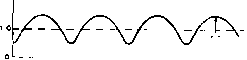 SwR = 3.0 Zl = 3.0 or о.зз Zo  SWR=<e ZL=ooh<e Figure 23 STANDING WAVES ON A TRANSMISSION LINE As shown at (A), the voltage and current are Constant on a transmission line which is terminated in its characteristic Impedance, assuming that losses are small enough so fhaf they may be neglected. (B) shows the variation in current or in voltage on a line terminated in a load with a reflection coefficient of 0.2 so that a standing wave ratio of hS to 7 fs sef up. Af (C) fhe reflection Coefficient has been increased to 0.5, with the formation of a 3 to I standing-wave ratio on the line. At (D) the line has been terminated in a load which has a reflection coefficient of 1,0 (short, open circuit, or a pure reactance) sa that all the energy is reflected with the formation af an infinite standing-wave ratio. tent and voltage along the line will become more uniform. The foregoing assumes, of course, a purely resistive (non-reactive) load. If the load is reactive, standing waves also will be formed. But with a reactive load the nodes will occur at different locations ftom the node locations encountered with wtong-value resistive termination. A well built 500- to 600-ohm transmission line may be used as a resonant feeder for lengths up to several hundred feet with very low loss, so long as the amplitude of the standing waves (ratio of maximum to minimum voltage along the line) is not too great. The HANDBOOK Tuned Lines 425 amplitude, in turn, depends upon the mismatch at the line termination. A line of no. 12 wire, spaced 6 inches with good ceramic or plastic spreaders, has a surge impedance of approximately 600 ohms, and makes an excellent tuned feeder for feeding anything between 60 and 6000 ohms (at frequencies below 30 Mc). If used to feed a load of higher or lower impedance than this, the standing waves become great enough in amplitude that some loss will occur unless the feeder is kept short. At frequencies above 30 Mc, the spacing becomes an appreciable fraction of a wavelength, and radiation from the line no longer is negligible. Hence, coaxial line or close-spaced parallel-wire line is recommended for v-h-f work. If a transmission line is not perfectly matched, it should be made resonant, even though the amplitude of the standing waves (voltage variation) is not particularly great. This prevents reactance from being coupled into the final amplifier. A feed system having moderate standing waves may be made to present a nonreactive load to the amplifier either by tuning or by pruning the feeders to approximate resonance. Usually it is preferable with tuned feeders to have a current loop (voltage minimum) at the transmitter end of the line. This means that when voltage- feeding an antenna, the tuned feeders should be made an odd number of quartet wavelengths long, and when current-feeding an antenna, the feeders should be made an even number of quarter wavelengths long. Actually, the feeders are made about 10 per cent of a quarter wave longer than the calculated value (the value given in the tables) when they are to be series tuned to resonance by means of a capacitor, instead of being trimmed and pruned to resonance. When tuned feeders are used to feed an antenna on more than one band, it is necessary to compromise and make provision for both series and parallel tuning, inasmuch as it is impossible to cut a feeder to a length that will be optimum for several bands. If a voltage loop appears at the transmitter end of the line on certain bands, parallel tuning of the feeders will be required in order to get a transfer of energy. It is impossible to transfer energy by inductive coupling unless current is flowing. This is effected at a voltage loop by the presence of the resonant tank circuit formed by parallel tuning of the antenna coil. 21-12 Line Discontinuities ]n the previous discussion we have assumed a transmission line which was uniform throughout its length. In actual practice, this is usually not the case. Whenever there is any sudden change in the characteristic impedance of the line, partial reflection will occur at the point of discontinuity. Some of the energy will be transmitted and some reflected, which is essentially the same as having some of the energy absorbed and some reflected in so far as the effect upon the line from the generator to that point is concerned. The discontinuity can by ascribed a reflection coefficient just as in the case of an unmatched load. In a simple case, such as a finite length of uniform line having a characteristic impedance of 500 ohms feeding into an infinite length of uniform line having a characteristic impedance of 100 ohms, the behavior is easily predicted. The infinite 100 ohm line will have no standing waves and will accept the same power from the 500 ohm line as would a 100 ohm resistor, and the rest of the energy will be reflected at the discontinuity to produce standing waves from there back to the generator. However, in the case of a complex discontinuity placed at an odd distance down a line terminated in a complex impedance, the picture becomes complicated, especially when the discontinuity is neither sudden nor gradual, but intermediate between the two. This is the usual case with amateut lines that must be etected around buildings and trees. In any case, when a discontinuity exists somewhere on a line and is not a smooth, gradual change embracing several wavelengths, it is not possible to avoid standing waves throughout the entire length of the line. If the discontinuity is sharp enough and is great enough to be significant, standing waves must exist on one side of the discontinuity, and may exist on both sides in many cases. Antennas and Antenna Matching Antennas for the lower frequency portion of the h-f spectrum (perhq>s from 1.8 to 7.0 Mc), and temporary or limited use antennas for the upper portion of the h-f range, usually are of a relatively simple type in which directivity is not a prime consideration. Also, it often is desirable, in amateur work, that a single antenna system be capable of operation at least on the 3.5-Mc. and 7.0-Mc. range, and preferably on other frequency ranges. Consequently, the first portion of this chapter will be devoted to a discussion of such antenna systems. The latter portion of the chapter is devoted to the general problem of matching the antenna transmission line to antenna systems of the fixed type. Matching rhe antenna transmission line to the rotatable directive array is discussed in Chapter Twenty-five. 22-1 End-Fed Half-Wave Horizontal Antennas The half-wave horizontal dipole is the most common and the most practical antenna for the З-5-Мс. and 7-Mc. amateur bands. The form of the dipole, and the manner in which it is fed are capable of a large number of variarions. Figure 2 shows a number of practicable forms of the simple dipole antenna along with methods of feed. Usually a high-frequency doublet is mounted as high and as much in the clear as possible, for obvious reasons. However, it is sometimes justifiable to bring part of the radiating system directly to the transmitter, feeding the antenna without benefit of a transmission line. This is permissible when (1) there is insufficient room to erect a 75- or 80-meter horizontal dipole and feed line, (2) when a long wire is also to be operated on one of the higher frequency bands on a harmonic. In either case, it is usually possible to get the main portion of the antenna in the clear because of its length. This means that the power lost by bringing the antenna directly to the transmitter is relatively small. Even so, it is not best practice to bring the high-voltage end of an anteima into the operating room because of the increased difficulty in eliminating BCI and TVI. For this reason one should dispense with a feed line in conjunction with a Hertz antenna only as a last resort. End-Fed The end-fed antenna has no form Antennas of transmission line to couple it to the transmitter, but brings the radiating portion of the antenna right down to the transmitter, where some form of coupling system is used to transfer energy to the antenna. Figure 1 shows two common methods of feeding the Fuchs antenna or end-fed Hertz. 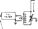 ANY NUMBER OF HALF-WAVES- FROM TRANSMITTER TVI FILTER HIGH CAPACITANCE ANY EVEN NUMBER OF QUARTER -cO= WAvLs -LOW 7] CAPACITANCE Figure 1 THE END-FED HERTZ ANTENNA Showing the manner In which an end-fed Hettz antenna may be fed through a low-impedance line and low-pass filter by using a resonant tank circuit as at (A), or tbroogb the use of a reverse-connected pi netvfork as at (B). Some harmonic-attenuating provision (in addition to the usual low-pass TVI filter) must be included in the coupling system, as an end-fed antenna itself offers no discrimination against harmonics, either odd or even. The end-fed Hertz antenna has rather high losses unless at least three-quarters of the radiator can be placed outside the operating room and in the clear. As there is r-f voltage at the point where the antenna enters the operating room, the insulation at that point should be several times as effective as the insulation commonly used with low-voltage feeder systems. This anteiuia can be operated on all of its higher harmonics with good efficiency, and can be operated at half frequency against ground as a quarter-wave Marconi. As the frequency of an antenna is raised slightly when it is bent anywhere except at a voltage or current loop, an end-fed Hertz antenna usually is a few per cent longer than a straight half-wave doublet for the same frequency, because, ordinarily, it is impractical to bring a wire in to the transmitter without making several bends. The Zepp Antenna The zeppelin or zepp an-System tetma system, illustrated in figure 2A is very convenient when it is desired to operate a single radiating wire on a number of harmonically related frequencies. The zepp antenna system is easy to tune, and can be used on several bands by merely retuning the feeders. The overall efficiency of the zepp antenna system is not quite as high for long feeder lengths as for some of the an-teima systems which employ non-resonant transmission lines, but where space is limited and where operation on more than one band is desired, the zepp has some decided advantages. As the radiating portion of the zepp antenna system must always be some multiple of a half wave long, there is always high voltage present at the point where the live zepp feeder attaches to the end of the radiating portion of the anteiuia. Thus, this type of zepp antenna system is voltage fed, Stub-Fed Zepp- Figure 2C shows a modifica-Type Radiator tion of the zepp-type antetma system to allow the use of a non-resonant transmission line between the radiating portion of the antenna and the transmitter. The zepp portion of the antenna is resonated as a quarter-wave stub and the non-resonant feeders are connected to the stub at a point where standing waves on the feeder are minimized. The procedure for making these adjustments is described in detail in Section 22-8 This type of antenna system is quite satisfactory when it is necessary physically to end feed the antenna, but where it is necessary also to use non-resonant feeder between the transmitter and the radiating system. 22-2 Center-Fed Half-Wave Horizontal Antennas The center feeding of a half-wave antenna system is usually to be desired over an end-fed system since the center-fed system is inherently balanced to ground and is therefore less likely to be troubled by feeder radiation. A number of center-fed systems are illustrated in figure 2. The Tuned The current-fed doublet with Doublet spaced feeders, sometimes called a center-fed zepp, is an inherently balanced system if the two legs of the radiator are electrically equal. This fact holds true regardless of the frequency, or of the harmonic, on which the system is operated. The system can successfully be operated over a wide range of frequencies if the system as a whole (both tuned feeders and the center-fed flat top) can be resonated to the operating frequency. It is usually possible to tune such an antenna system to resonance with the aid of a tapped coil and a tuning capacitor that can optionally be placed either zepp 300-600 aline = STUB-FED END-FED TYPES -0.95 X/2- -<n - TUNED DOUBLET
SHORTED ЗОО-вООЛ line -0.95 Л/2 -lC3f 300-600 OHM LINE OPEN qUARTER-WAVE STUB-FED 0 95 х/г- q-FED  600 a LINE - C0o о- © four-wire line-fed - сз <o- -0.95 л/г --га- 150 л TWINLEAD 0.193 OF FREE SPACE WAVELENGTH OR 0.77 OF Л/4 TWINLEAD 300 Д TWINLEAD ANY LENGTH Figure 2 ALTERNATIVE METHODS OF FEEDING A HALF-WAVE DIPOLE © twinlead folded dipole 300n TWINLEAD LOW SIDE OPENED /rv IN CENTER y<) 2-WIRE DOUBLET 300 OHM TWINLEAD ANY LENGTH OR FOLDED DIPOLE- 2 0Re FEEDER SPREADERS © DELTA-MATCHED FOR DELTA DIMENSIONS = SEECHAP19 DOUBLET 300 OHM TWINLEAD ANY LENGTH 600 OHM LINE ANY LENGTH -0.95 X/2- STANOARD DOUBLET 75 n TWINLEAD ANY LENGTH -0.95 Л/г © CO-AX FED DOUBLET -0.95 л/г- -ЧСЭ О- OFF-CENTER D = 14% OF TOTAL LENGTH N 14WIRE CENTER-FED TYPES in series with the antenna coil or in parallel with it. A series tuning capacitor can be placed in series with one feeder leg without unbalancing the system. The tuned-doublet antenna is shown in figure 2D. The antenna is a current-fed system when the radiating wire is a half wave long electrically, or when the system is operated on its odd harmonics, but becomes a voltage-fed radiator when operated on its even harmonics. The antenna has a different radiation pattern when operated on its harmonics, as would be expected. The arrangement used on the second harmonic is better known as the Prank-lin colinear array and is described in Chapter Twenty-three. The pattern is similar to a /wave dipole except that it is sharper in the broadside direction. On higher harmonics of operation there will be multiple lobes of radiation from the system. Figures 2E and 2F show alternative arrangements for using an untuned transmission line between the transmitter and the tuned-doublet radiator. In figure 2E a half-wave shorted line is used to resonate the radiating system, while in figure 2F a quarter-wave open line is utilized. The adjustment of quarter-wave and half-wave stubs is discussed in Section 19-8. Doublets with The average value of feed im-Quorter-Wove pedance for a center-fed half-Transformers wave doublet is 75 ohms. The actual value varies with height and is shown in Chapter Twenty-one. Other methods of matching this rather low value of impedance to a medium-impedance transmission line are shown in (G), (H), and (I) of figure 2. Each of these three systems uses a quarter-wave transformer to accomplish the impedance transformation. The only difference between the three systems lies in the type of transmission line used in the quarter-wave transformer. (G) shows the Johnson Q system whereby a line made up of /-inch dural tubing is used for the low-impedance linear transformer. A line made up in this manner is frequently called a set of Q bars. Illustration (H) shows the use of a four-wire line as the linear transformer, and (I) shows the use of a piece of 150-ohm Twin-Lead electrically %-wave in length as the transformer between the center of the dipole and a piece of 300-ohm Twin-Lead. In any case the impedance of the quarter-wave transformer will be of the order of 150 to 200 ohms. The use of sections of transmission line as linear transformers is discussed in detail in Section 22-8. Multi-Wire An alternative method for increas-Doublets ing the feed-point impedance of a dipole so that a medium-imped- ance transmission line may be used is shown in figures 2j and 2K. This system utilizes more than one wire in parallel for the radiating element, but only one of the wires is broken for attachment of the feeder. The most common arrangement uses two wires in the flat top of the antenna so that an impedance multiplication of four is obtained. The antenna shown in figure 2J is the so-called Twin-Lead folded dipole which is a commonly used antenna system on the medium-frequency amateur bands. In this arrangement both the antenna and the transmission line to the transmitter are constructed of 300-ohm Twin-Lead. The flat top of the antenna is made slightly less than the conventional length (462/Fmc. instead of 468/Fmc. for a single-wire flat top) and the two ends of the Twin-Lead are joined together at each end. The center of one of the conductors of the Twin-Lead flat top is broken and the two ends of the Twin-Lead feeder are spliced into the flat top leads. As a protection against moisture pieces of flat polyethylene taken from another piece of 300-ohm Twin-Lead may be molded over the joint between conductors with the aid of an electric iron or soldering iron. Better bandwidth characteristics can be obtained with a folded dipole made of ribbon line if the two conductors of the ribbon line are shorted a distance of 0.82 (the velocity factor of ribbon line) of a free-space quarter wavelength from the center or feed point. This procedure is illustrated in figure ЗА. An alternative arrangement for a Twin-Lead folded dipole is illustrated in figure 3B. This type of half-wave antenna system is convenient for use on the 3.5-Mc. band when the 116 to 132 foot distance required for a full half-wave is not quite available in a straight line, since the single-wire end pieces may be bent away or downward from the direction of the main section of the antenna. Figure 2K shows the basic type of 2-wire doublet or folded dipole wherein the radiating section of the system is made up of standard antenna wire spaced by means of feeder spreaders. The feeder again is made of 300-ohm Twin-Lead since the feed-point impedance is approximately 300 ohms, the same as that of the Twin-Lead folded dipole. The folded-dipole type of antenna has the broadest response characteristic (greatest bandwidth) of any of the conventional half-wave antenna systems constructed of small wires or conductors. Hence such an antenna may be operated over the greatest frequency range without serious standing waves of any common half-wave antenna type. The increased bandwidth of the multi-wire doublet type of radiator, and the fact that the feed-point resistance is increased several 46 г Fmc. Fmc. ЭОО-ОНМ RIBBON 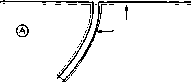 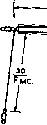 ®  300-ohm ribbon Figure 3 FOLDED DIPOLE WITH SHORTING STRAPS TAe impedance match and bandwidth characteristics of a folded dipole maybe improved by shorting the two wires of the ribbon a distance out from the center equal to the velocity factor of fhe ribbon times the half-length of fhe dipole as shown at (A), An alternative arrangement with bent down ends for space conservation ts illustrated at (B), times over the radiation resistance of the element, have both contributed to the frequent use of the multi-wire radiator as the driven element in a parasitic antenna array. Delta-Matched These two types of radiat-Doublet and ing elements are shown in Standard Doublet figure 2L and figure 2M. The delta-matched doublet is described in detail in Section 22-8 of this chapter. The standard doublet, shown in figure 2M, is fed in the center by means of 75-ohm Twin-Lead, either the transmitting or the receiving type, or it may be fed by means of twisted-pair feeder or by means of parallel-wire lamp-cord. Any of these types of feed Hne will give an approximate match to the center impedance of the dipole, but the 75-ohm Twin-Lead is far to be preferred over the other types of low-impedance feeder due to the much lower losses of the polyethylene-dielectric transmission line. The coaxial-cable-fed doublet shown in figure 2N is a variation on the system shown in figure 2M. Either 52-ohm coaxial cable or 75-ohm coaxial cable may be used to feed the center of the dipole, although the 75-ohm type 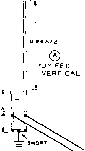 ® STUB-FED VERTICAL © L-C-FED VERTICAL 3O0-6OQ л LINE 300-eOOAL(NE Figure 4 HALF-WAVE VERTICAL ANTENNA SHOWING ALTERNATIVE METHODS OF FEED will give a somewhat better impedance match at normal antenna heights. Due to the asymmetry of the coaxial feed system difficulty may be encountered with waves traveling on the outside of the coaxial cable. For this reason the use of Twin-Lead is normally to be preferred over the use of coaxial cable for feeding the center of a half-wave dipole. Off-Center The system shown in figure Fed Doublet 2(0) is sometimes used to feed a half-wave dipole, especially when it is desired to use the same antenna on a number of harmonically-related frequencies. The feeder wire (no. 14 enamelled wire should be used) is tapped a distance of 14 per cent of the total length of the antenna either side of center. The feeder wire, operating against ground for the return current, has an impedance of approximately 600 ohms. The system works well over highly conducting ground, but will introduce rather high losses when the antenna is located above rocky or poorly conducting soil. The off-center fed antenna has a further disadvantage that it is highly responsive to harmonics fed to it from the transmitter. The effectiveness of the antenna system in radiating harmonics is of course an advantage when operation of the antenna on a number of frequency bands is desired. But it is necessary to use a harmonic filter to insure that only the desired frequency is fed from the transmitter to the antenna. 22-3 The Half-Wave Vertical Antenna The half-wave vertical antenna with its bottom end from 0.1 to 0.2 wavelength above 1 ... 39 40 41 42 43 44 45 ... 80 |
||||||||||||||||||||||||||||||||||||||||||||||||||||||||||||||||||||||||||||||||||||||||||||||||||||||||||||||||||||||||||||||||||||||||||||||||||||||||||||||||||||||||||||||||||||||||||
|
© 2026 AutoElektrix.ru
Частичное копирование материалов разрешено при условии активной ссылки |