 |
 |
 |
| Главная Журналы Популярное Audi - почему их так назвали? Как появилась марка Bmw? Откуда появился Lexus? Достижения и устремления Mercedes-Benz Первые модели Chevrolet Электромобиль Nissan Leaf |
Главная » Журналы » Simple coaxial reflectometer 1 ... 40 41 42 43 44 45 46 ... 80 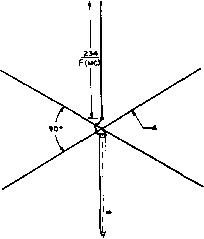 RAOIALSEACHj &2 OHM COAXIAL LINE. CENTER CONDUCTOR CONNECTS TO VERTICAL WHIP /-LOADING COIL / APPROXIMATELY Эв TURNS V #l2WIRe. 4.5 DIAMETER < Г ANO I FOOT UDNG 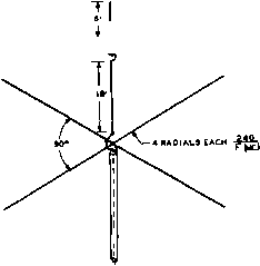 I -52 OHM COAXIAL LINE 45 FEET LONG Figure 5 THE LOW-FREQUENCY GROUND PLANE ANTENNA Tbe radials of the ground plane antenna should lie in a horizontal plane, although slight departures from this caused by nearby objects is allowable. The whip may be mounted on a short post, or on the roof of a building. The wire radials may slope downwards towards their tips, acting as guy wires for the installation. ground is an effective transmitting antenna for low-angle radiation, where ground conditions in the vicinity of the antenna are good. Such an antenna is not good for short-range sky-wave communication, such as is the normal usage of the З-5-Мс. amateur band, but is excellent for short-range ground-wave communication such as on the standard broadcast band and on the amateur 1.8-Mc. band. The vertical antenna normally will cause greater BCI than an equivalent horizontal antenna, due to the much greater ground-wave field intensity. Also, the vertical antenna is poor for receiving under conditions where man-made interference is severe, since such interference is predominantly vertically polarized. Three ways of feeding a half-wave vertical antenna from an untuned transmission line are illustrated in figure 4. The J-fed system shown in figure 4A is obviously not practicable except on the higher frequencies where the extra length for the stub may easily be obtained. However, in the normal case the ground-plane vertical antenna is to be recommended over the J-fed system for high frequency work. 22-4 The Ground Plane Antenna An effective low angle radiator for any ama- Figure 6 80 METER LOADED GROUND PLANE ANTENNA Number of turns in loading coil to be adjusted until onfenno sysfem resonofes of desired frequency in 80 meter band. teur band is the ground-plane antenna, shown in figure 5. So called because of the radial ground wires, the ground-plane antenna is not affected by soil conditions in its vicinity due to the creation of an artificial ground system by the radial wires. The base impedance of the ground plane is of the order of 30 to 35 ohms, and it may be fed with 52-ohm coaxial line with оц1у a slight impedance mis-match. For a more exact match, the ground-plane antenna may be fed with a 72-ohm coaxial line and a quarter-wave matching section made of 52-ohm coaxial line. The angle of radiation of the ground-plane anteima is quite low, and the antenna will be found less effective for contacts under 1000 miles or so on the 80 and 40 meter bands than a high angle radiator, such as a dipole. However, for DX contacts of 1000 miles or more, the ground-plane antenna will prove to be highly effective. The 80-Meter A vertical antenna of 66 feet Loaded in height presents quite a prob- Ground-Plane lem on a small lot, as the supporting guy wires will tend to take up quite a large portion of the lot. Under such conditions, it is possible to shorten the length of the vertical radiator of the ground-plane by the inclusion of a loading coil in the vertical whip section. The ground-plane antenna may be artificially loaded in this manner so that a 25-foot vertical whip may be used for the radiator. Such an antenna is shown in figure 6. The loaded ground-plane tends to have a rather high operating Q and operates only over a narrow band of frequencies. An operating range of about 100 kilocycles with a low SWR is possible on 80 meters. Operation over a larger frequency range is possible if a.higher standing wave ratio is tolerated on the transmission line. The radiation resistance of a loaded 80-meter ground-plane is about 15 ohms. A quarter wavelength (45 feet) of 52-ohm coaxial line will act as an efficient feed line, presenting a load of approximately 180 ohms to the transmitter. 22-5 The Marconi Antenna A grounded quarter-wave Marconi antenna, widely used on frequencies below 3 Mc, is sometimes used on the 3.5-Mc. band, and is also used in v-h-f mobile services where a compact antenna is required. The Marconi type antenna allows the use of half the length of wire that would be required for a half-wave Hertz radiator. The ground acts as a mirror, in effect, and takes the place of the additional quarter-wave of wire that would be required to reach resonance if the end of the wire were not returned to ground. The fundamental practical form of the Marconi antenna system is shown in figure 7. Other Marconi antennas differ from this type primarily in regard to the method of feeding the energy to the radiator. The feed method shown in figure 7B can often be used to advantage, particularly in mobile work. Variations on the basic Marconi antenna are shown in the illustrations of figure 8. Figures 8B and 8C show the L -type and T -type Marconi antennas. These arrangements have been more or less superseded by the top-loaded forms of the Marconi antenna shown in figures 8D, 8E, and 8F. In each of these latter three figures an antenna somewhat less than one quarter wave in length has been loaded to increase its effective length by the insertion of a loading coil at or near the top of the radiator. The arrangement shown at figure 8D gives the least loading but is the most practical mechanically. The system shown at figure 8E gives an intermediate amount of loading, while that shown at figure 8F, utilizing a hat just above the loading coil, gives the greatest amount of loading. The object of all the top-loading methods shown is to produce an increase in the effective length of the radiator, and thus to raise the point of maximum current in the radiator as far as pos- LINC FftOM TRANS. < COAX. FROM TRANS. Figure 7 FEEDING A QUARTER-WAVE /MARCONI ANTENNA ly/ien on open-wfre line is fo be used, it may be link coxipled to a series-resonant circuit between the bottom end of the Marconi and ground, as at (A). Alternatively, a reasonably goad impedance match may be obtained between 52-ohm coaxial line and the bottom of a resonant quarter-wave antenna, as illustrated at (B) above. sible above ground. Raising the maximum-current point in the radiator above ground has two desirable results: The percentage of low-angle radiation is increased and the amount of ground current at the base of the radiator is reduced, thus reducing the ground losses. To estimate whether a loading coil will probably be required, it is necessary only to note if the length of the antenna wire and ground lead is over a quarter wavelength; if so, no loading coil is needed, provided the series tuning capacitor has a high maximum capacitance. Amateurs primarily interested in the higher frequency bands, but who like to work 80 meters occasionally, can usually manage to resonate one of their antennas as a Marconi by working the whole system, feeders and all, against a water pipe ground, and resorting to a loading coil if necessary. A high-frequency-rotary, zepp, doublet, or single-wire-fed antenna will make quite a good 80-meter Marconi if high and in the clear, with a rather long feed line to act as a radiator on 80 meters. Where two-wire feeders are used, the feeders should be tied together for Marconi operation. Importance of With a quarter-wave anten- Ground Connection na and a ground, the antenna current generally is measured with a meter placed in the antenna circuit close to the ground connection. If this Figure 8 LOADING THE MARCONI ANTENNA T/ie various loading systems are discussed in the accompanying text. ® ® coils LESS THAM о current flows through a resistor, or if the ground itself presents some resistance, there will be a power loss in the form of heat. Improving the ground connection, therefore, provides a definite means of reducing this power loss, and thus increasing the radiated power. The best possible ground consists of as many wires as possible, each at least a quarter wave long, buried just below the surface of the earth, and extending out from a common point in the form of radials. Copper wire of any size larger than no. 16 is satisfactory, though the larger sizes will take longer to disintegrate. In fact, the radials need not even be buried; they may be supported just above the earth, and insulated from it. This arrangement is called a counterpoise, and operates by virfue of its high capacitance to ground. If the antenna is physically shorter than a quarter wavelength, the antenna current is higher, due to lower radiation resistance. Consequently, the power lost in resistive soil is greater. The importance of a good ground with short, inductive-loaded Marconi radiators is, therefore, quite obvious. With a good ground system, even very short (one-eighth wavelength) antennas can be expected to give a high percentage of the efficiency of a quarter-wave antenna used with the same ground system. This is especially true when the short radiator is top loaded with a high Q (low loss) coil. Woter-Pipe Water pipe, because of its com-Grounds paratively large surface and cross section, has a relatively low r-f resistance. If it is possible to attach to a junction of several water pipes (where they branch in several directions and run for some distance under ground), a satisfactory ground connection will be obtained. If one of the pipes attaches to a lawn or garden sprinkler system in the immediate vicinity of the antenna, the effectiveness of the system will approach that of buried copper radials. The main objection to water-pipe grounds is the possibility of high resistance joints in the pipe, due to the dope put on the coupling threads. By attaching the ground wire to a junction with three or more legs, the possibility of requiring the main portion of the r-f current to flow through a high resistance connection is greatly reduced. The presence of water in the pipe adds nothing to the conductivity; therefore it does not relieve the problem of high resistance joints. Bonding the joints is the best insurance, but this is, of course, impracticable where the pipe is buried. Bonding together with copper wire the various water faucets above the surface of the ground will improve the effectiveness of a water-pipe ground system hampered by high-resistance pipe couplings. Marconi A Marconi antenna is an odd Dimensions number of electrical quarter waves long (usually only one quarter wave in length), and is always resonated to the operating frequency. The correct loading of the final amplifier is accomplished by varying the coupling, rather than by detuning the antenna from resonance. Physically, a quarter-wave Marconi may be made anywhere from one-eighth to three-eighths wavelength overall, meaning the total length of the antenna wire and ground lead from the end of the antenna to the point where the ground lead attaches to the junction of the radials or counterpoise wires, or where the water pipe enters the ground. The longer the antenna is made physically, the lower will be the current flowing in the ground connection, and the greater will be the overall radiation efficiency. However, when the antenna length exceeds three-eighths wavelength, the antenna becomes difficult to resonate by means of a series capacitor, and it begins to take shape as an end-fed Hertz, requiring a method of feed such as a pi network. A radiator physically much shorter than a -XMAT LOWEST FREaOENCY- *-X/e-[ -X/ft- ® и feemr spreaders RESONANT LINE © Fmc. -4 feeder 5PBE*ce s 3QQ д. twinlead Fmc, Figure 9 THREE EFFECTIVE SPACE CONSERVING ANTENNAS The arrangements shown at (A) and (B) are satisfactory where resonant feed line can be used. However, non-resonant 75-ohm feed line may be used in the arrangement at (A) when the dimensions In wavelengths are as shown. In the arrangement shown at (B) low standing waves will be obtained on the feed line when the overall length of the antenna is a half wave. The arrangement shown at (C) may be tuned for any reasonable length of flat top to give a minimum of standing waves on the transmission line. quarter wavelength can be lengthened electrically by means of a series loading coil, and used as a quarter-wave Marconi. However, if the wire is made shorter than approximately one-eighth wavelength, the radiation resistance will be quite low. This is a special problem in mobile work below about 20-Mc. 22-6 Space-Conserving Antennas In many cases it is desired to undertake a considerable amount of operation on the 80-meter or 40-meter band, but sufficient space is simply not available for the installation of a half-wave radiator for the desired frequency of operation. This is a common experience of apartment dwellers. The shortened Marconi antenna operated against a good ground can be usedunder certain conditions, but the shortened Marconi is notorious for the production of broadcast interference, and a good ground connection is usually completely unobtainable in an apartment house. 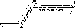 wires shorted together at end >A<lUAXlAL FEED UNE Figure 10 TWIN-LEAD MARCONI ANTENNA FOR THE 80 AND 160 METER BANDS Essentially, the problem in producing an antenna for lower frequency operation in restricted space is to erect a short radiator which is balanced with respect to ground and which is therefore independent of ground for its operation. Several antenna types meeting this set of conditions are shown in figure 9. Figure 9A shows a conventional center-fed doublet with bent-down ends. This type of antenna can be fed with 75-ohm Twin-Lead in the center, or it may be fed with a resonant line for operation on several bands. The overall length of the radiating wire will be a few per cent greater than the normal length for such an antenna since the wire is bent at a position intermediate between a current loop and a voltage loop. The actual length will have to be determined by the cut-and-try process because of the increased effect of interfering objects on the effective electrical length of an antenna of this type. Figure 9B shows a method for using a two-wire doublet on one half of its normal operating frequency. It is recommended that spaced open conductor be used both for the radiating portion of the folded dipole and for the feed line. The reason for this recommendation lies in the fact that the two wires of the flat top are not at the same potential throughout their length when the antenna is operated on one-half frequency. Twin-Lead may be used for the feed line if operation on the frequency where the flat top is one-half wave in length is most common, and operation on one-half frequency is infrequent. However, if the antenna is to be used primarily on one-half frequency as shown, it should be fed by means of an open-wire line. If it is desired to feed the antenna with a non-resonant line, a quarter-wave stub may be connected to the antenna at the points X, X in figure 9B. The stub should be tuned and the transmission line connected to it in the normal manner. The antenna system shown in figure 9C may be used when not quite enough length is available for a full half-wave radiator. The dimen- HANDBOOK Space Conserving Antennas 435 for detail see fig. a phenolic block ZX l.i X wrap cables and block with scotch electricaltape space blocks 6 apart along balun  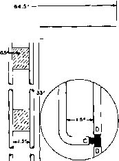 FIGURC A cutoffshield and outer jacket as shown. allow dielectric to extend part way to other cable. cover all exposed shield and dielectric on both cables with a continuous wrapping of scotch electrical tape to exclude moisture. keep balun at least f clear of ground and other objects. for detail see figure b- 52 ohm rg-e/u, any length - FIGURES remove outer jacket from a short length of cable a5 shown here. unbraid the shield of coax c. cutoffthe dielectric and inner conductor flush with the outer jacket. do mot cut the shield. wrapshield of coax с abound shield of coax d. solder the connection, being very careful not to damage the dielectric material. hold cable d straight while soldering. cover the area with a continuous wrapping of scotch electrical tape. no connection to inner conductors. 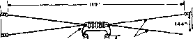 FOR DETAIL SEE FIG. A phenolic block 2xi.5 x0.5 - - j! wrap cables and block with scotch electricaltape. space Blocks в'apart along balun 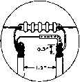 FIGURE A cutoff shield and outer jacket as shown. allow dielectric to extend part way to other cable. cover all exposed shield and dielectric on both cables with a continuous wrapping of scotch electrical tape to exclude moisture. WA KEEP BALUN AT LEAST - tLEAR OF GROUND AND OTHER OBJECTS. e-CLEAR for detail see figure в-- 52 ohm rg-S/u, any length- CCB the two wires may be spread either horizontally or vertically 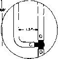 FIGURE в remove outer jacket from a short length of cable as shown here. unbraid the shield of coax c, cutoff the dielectric and inner conductor flush with the outer jacket. do not cut the shield. wrapshield of coax с around shield of coax d. solder the connection, being very careful not to damage The dielectric material. hold cable d straight while soldering. cover the area with a continuous wrapping of scotch electrical tape. hocon-nection to inner conductors. DIMENSIONS SHOWN НЕЙЕ ЛЙЕ FOR THE 40 METER BANO. THIS ANTENNA MA r BE BUILT FOR OTHER BANDS BY USINS DIMENSIONS THAT ARE MULTIPLES OR SUBMULTIPLES OF THE DIMENSIONS SHOWN. BALUN SPACING IS I.SON ALL BANDS- DIMENSIONS SHOWN HERE ARE FOR THE tO METER BAND. THIS ANTENNA MAY BE BUILT FOR OTHER BAHOS BY USINS DIMENSIONS THAT ARE MULTIPLES OR SUBMULTIPLES OF THE OIMENSIONS SHOWN. BALUNSPACINS IS 1.5-ON ALL BANDS. Figure 11 HALF-WAVE ANTENNA WITH QUARTER-WAVE UNBALANCED TO BALANCED TRANSFORMER (BALUN) FEED SYSTEM FOR 40.METER OPERATION Figure 12 BROADBAND ANTENNA WITH QUARTER-WAVE UNBALANCED TO BALANCED TRANSFORMER (BALUN) FEED SYSTEM FOR 80.METER OPERATION sions in terms of frequency are given on the drawing. An antenna of this type is 93 feet long for operation on 3600 kc. and 86 feet long for operation on 3900 kc. This type of antenna has the additional advantage that it may be operated on the 7-Mc. and 14-Mc. bands, when the flat top has been cut for the 3.5-Mc. band, simply by changing the position of the shorting bar and the feeder line on the stub. A sacrifice which must be made when using a shortened radiating system, as for example the types shown in figure 9, is in the bandwidth of the radiating system. The frequency range which may be covered by a shortened antenna system is approximately in proportion to the amount of shortening which has been employed. For example, the antenna system shown in figure 9C may be operated over the range from 3800 kc. to 4000 kc. without serious standing waves on the feed line. If the antenna had been made full length it would be possible to cover about half again as much frequency range for the same amount of mismatch on the extremes of the frequency range. The Twin-Lead Morconi Antenna Much of the power loss in the Marconi antenna is a result of low radiation resistance and high ground resistance. In some cases, the ground resistance may even be be higher than the radiation resistance, causing a loss of 50 per cent or more of the transmitter power оифиг. If the radiation resistance of the Marconi antenna is raised, the amount of power lost in the ground resistance is proportionately less. If a Marconi antenna is made out of 300 ohm TV-type ribbon line, as shown in figure 10, the radiation resistance of the antenna is raised from a low value of 10 or 15 ohms to a more reasonable value of 40 to 60 -ANTENNA 3.e 3.7 3.4 FREQUENCY (mc) Figure 13 SWR CURVE OF BO-METER BROAD-BAND DIPOLE 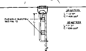 INNER CONDUCTOR NOT USED-* SEE FiO.ia FOR CONNECTION S2 0HM COAXIAL LINE ohms. The ground losses are now reduced by a factor of 4. In addition, the antenna may be directly fed from a 50-ohm coaxial line, or directly from the unbalanced output of a pi- network transmitter. Since a certain amount of power may still be lost in the ground connection, it is still of greatest importance that a good, low resistance ground be used with this antenna. The Collins Shown in figures 11 and 12 Brood-bond are broad-band dipoles for Dipole System the 40 and 80 meter amateur bands, designed by Collins Radio Co. for use with the Collins 32V-3 and KW-1 transmitters. These fan-type dipoles have excellent broad-band response, and are designed to be fed with a 52-ohm unbalanced coaxial line, making them suitable for use with many of the other modern transmitters, such as the Barker and Williamson 5100, Johnson Ranger, and Viking. The antenna system consists of a fan-type dipole, a balun matching section, and a suitable coaxial feedline. The Q of the half-wave 80 meter doublet is lowered by decreasing the effective length-to-diameter ratio. The frequency range of operation of the doublet is increased considerably by this change. A typical SWR curve for the 80 meter doublet is shown in figure 13. The balanced doublet is marched to the unbalanced coaxial line by the one-quarter wave balun. If desired, a shortened balun may be used (figure 14). The short balun is capacity loaded at the junction between the balun and the broad-band dipole. 22-7 Multi-Band Antennas The availability of a multi-band antenna is a great operating convenience to an amateur station. In most cases it will be found best to install an antenna which is optimum for the band which is used for the majority of the Figure 14 SHORT BALUN FOR 40 AND 80 METERS available operating time, and then to have an additional multi-band antenna which may be pressed into service for operation on another band when propagation conditions on the most frequently used band are not suitable. Most amateurs use, or plan to install, at least one directive array for one of the higher-frequency bands, but find that an additional antenna which may be used on the 3.5-Mc. and 7.0-Mc. band, or even up through the 28-Mc. band is almost indispensable. The choice of a multi-band antenna depends upon a number of factors such as the amount of space available, the band which is to be used for the majority of operating with the antenna, the radiation efficiency which is desired, and rhe type of antenna tuning network to be used at the transmitter. A number of recommended types are shown in the next pages. The 34-Wave Figure 15 shows an antenna Folded Doublet type which will be found to be very effective when a moderate amount of space is available, when most of the operating will be done on one band with occasional operation on the second harmonic. The system is quite satisfactory for use with high-power transmitters since a 600-ohm non-resonant line is used from the antenna to the transmitter and since the antenna system is balanced with respect to ground. With operation on the fundamental frequency of the antenna where the flat top is wave long the switch SW is left open. The system affords a very close match between the 600-ohm line and the feed point of the antenna. Kraus has reported a standing-wave ratio of proximately 1.2 to 1 over the 14-Mc. band when the antenna was located approximately one-half wave above ground. For operation on the second harmonic the switch SW is closed. The antenna is still an 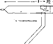 L= lb FOR iiao KC ANO 7150 KC, L 9в' FOR 7I0Q KC, ANO l*£SO KC. L = 49.6 FOR UZOD KC. AND MC. Figure 15 THE THREE-QUARTER WAVE FOLDED DOUBLET This onfenno orrongemenf will give very satisfactory operof/on with a 600-ohm feed /ine for operofion with the switch open on fbe fundomenfof frequency and with the switch closed on twice frequency. effective radiator on the second harmonic but the pattern of radiation will be different from that on the fundamental, and the standing-wave ratio on the feed line will be greater. The flat top of the antenna must be made of open wire rather than ribbon or tubular line. For greater operating convenience, the shorting switch may be replaced with a section of transmission line. If this transmission line is made one-quarter wavelength long for the fundamental frequency, and the free end of the line is shorted, it will act as an open circuit across the center insulator. At the second harmonic, the transmission line is one-half wavelength long, and reflects the low impedance of the shorted end across the center insulator. Thus the switching action is automatic as the frequency of operation is changed. Such an installation is shown in figure 16. The End-Fed The end-fed Hertz antenna Hertz shown in figure 17 is not as effective a radiating system as 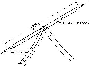 SHORTED END 600 OHM LINE TO TRANSMITTER L = 67 FT WHEN ANTENNA IS I9i FT. L=33FT 98 FT. L= 16.5 FT 49.6 FT Figure 16 AUTOMATIC BANDSWITCHING STUB FOR THE THREE-QUARTER WAVE FOLDED DOUBLET The antenna of Figure IS moy be used with a shorted stub line in place of the switch normally used for second harmonic operation. many other antenna types, but it is particularly convenient when it is desired to install an antenna in a hurry for a test, or for field-day work. The flat top of the radiator should be as high and in the clear as possible. In any event at least three quarters of the total wire length should be in the clear. Dimensions for optimum operation on various amateur bands are given in addition in figure 17. The End-Fed The end-fed Zepp has long Zepp been a favorite for multi-band operation. It is shown in figure 18 along with recommended dimensions for operation on various amateur band groups. -L, , 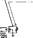 L-SEE BELOW- 3.5,7,1* AND 28 MC 3.5,7 AND 14 MC. Э.5 AND 7 MC 3.9 MC. AND2eMC. L=l3e L=I37 L=1Эв L= 120 Figure 17 RECOMMENDED LENGTHS FOR THE END-. FED HERTZ T SEE TABLE BELOW-
END-FED ZEPP FIGURE 18 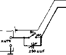 l-90 FOR eO-40 METER OPERATION Figure 19 A TWO-BAND MARCONI ANTENNA FOR 160-80 METER OPERATION Since this antenna type is an unbalanced radiating system, its use is not recommended with high-power transmitters where interference to broadcast listeners is likely to be encountered. The r-f voltages encountered at the end of zepp feeders and at points an electrical half wave from the end are likely to be quite high. Hence the feeders should be supported an adequate distance from surrounding objects and sufficiently in the clear so that a chance encounter between a passerby and the feeder is unlikely. The coupling coil at the transmitter end of the feeder system should be link coupled to the ouфut of the low-pass TVI filter in order to reduce harmonic radiation. The Two-Bond A three-eighths wavelength Marconi Antenna Marconi antenna may be operated on its harmonic frequency, providing good two band performance from a simple wire. Such an arrangement for operation on 160-80 meters, and 80-40 meters is shown in figure 19. On the fundamental (lowest) frequency, the antenna acts as a three-eighths wavelength series-tuned Marconi. On the second harmonic, the antenna is a current-fed three-quarter wavelength antenna operating against ground. For proper operation, the antenna should be resonated on its second harmonic by means of a grid-dip oscillator to the operating frequency most used on this particular band. The Q of the antenna is relatively low, and the antenna will perform well over a frequency range of several hundred kilocycles. The overall length of the antenna may be varied slightly to place its self-resonant frequency in the desired region. Bends or turns in the antenna tend to make it resonate higher in frequency, and it may be necessary to lengthen it a bit to resonate it at the chosen frequency. For fundamental operation, the series condenser is inserted in the circuit, and the antenna may be resonated to any point in the lower frequency band. As with any Marconi

CENTER-FED ANTENNA Figure 20 DIMENSIONS FOR CENTER-FED MULTI-BAND ANTENNA type antenna, the use of a good ground is essential. This antenna works well with transmitters employing coaxial antenna feed, since its transmitting impedance on both bands is in the neighborhood of 40 to 60 ohms. It may be attached directly to the output terminal of such transmitters as the Collins 32V and the Viking 11. The use of a low-pass TVI filter is of course recommended. The Center-Fed Multi-Band Antenna For multi-band operation, the center fed antenna is without doubt the best compromise. It is a balanced system on all bands, it requires no ground return, and when properly tuned has good rejection properties for the higher harmonics generated in the transmitter. It is well suited for use with the various multi-band 150-watt transmitters that are currently so popular. For proper operation with these transmitters, an antenna tuning unit must be used with the center-fed antenna. In fact, some sort of tuning unit is necessary for any type of efficient, multi-band antenna. The use of such questionable antennas as the off-center fed doublet is an invitation to TVI troubles and improper operation of the transmitter. A properly balanced antenna is the best solution to multi-band operation. When used in conjunction with an antenna tuning unit, it will perform with top efficiency on all of the major amateur bands. Several types of center-fed antenna systems are shown in figure 20. If the feed line is made up in the conventional manner of no. 12 or no. 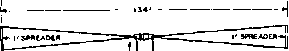 33 OR ев LONG- -300OHM OPEN-WIRE TV TYPE LINE
DIPOLE TO LIMIT IMPEDANCE EXCURSIONS ON HARMONIC FREQUENCIES  > WIRE  Figure 22 FOLDED-TOP DUAL-BAND ANTENNA 14 wire spaced 4 to 6 inches the antenna system is sometimes called a center-fed zepp. With this type of feeder the impedance at the transmitter end of the feeder varies from about 70 ohms to approximately 5000 ohms, the same as is encountered in an end-fed zepp antenna. This great impedance ratio requires provision for either series or parallel tuning of the feeders at the transmitter, and involves quite high r-f voltages at various points along the feed line. If the feed line between the transmitter and the antenna is made to have a characteristic impedance of approximately 300 ohms the excursions in end-of-feeder impedance are greatly reduced. In fact the impedance then varies from approximately 75 ohms to 1200 ohms. With this much lowered impedance variation it is usually possible to use series tuning on all bands, or merely to couple the antenna directly to the ouфut tank circuit or the harmonic reduction circuit without any separate feeder tuning provision. There are several practicable types of transmission line which can give an impedance of approximately 300 ohms. The first is, obviously, 300-ohm Twin-Lead. Twin-Lead of the receiving type may be used as a resonant feed line in this case, but its use is not recommended with power levels greater than perhs 150 watts, and it should not be used when lowest loss in the transmission line is desired. For power levels up to 250 watts or so, the transmitting type tubular 300-ohm line may be used, or the open-wire 300-ohm TV line may be employed. For power levels higher than this, a 4- wire transmission line, or a line built of one-quarter inch tubing should be used. Even when a 300-ohm transmission line is used, the end-of-feeder impedance may reach a high value, particularly on the second harmonic of the antenna. To limit the impedance excursions, a two-wire flat-top may be employed for the radiator, as shown in figure 21. The use of such a radiator will limit the impedance excursions on the harmonic frequencies of the antenna and make the operation of the antenna matching unit much less critical. The use of a two-wire radiator is highly recommended for any center-fed multi-band antenna. Folded Flat-Top As has been mentioned Dual-Band Antenna earlier, there is an increasing tendency among amateur operators to utilize rotary or fixed arrays for the 14-Mc. band and those higher in frequency. In order to afford complete coverage of the amateur bands it is then desirable to have an additional system which will operate with equal effectiveness on the 3.5-Mc. and 7-Mc. bands, but this low-frequency antenna system will not be required to operate on any bands higher in frequency than the 7-Mc. band. The antenna system shown in figure 22 has been developed to fill this need. This system consists essentially of an open-line folded dipole for the 7-Mc. band with a special feed system which allows the an-tetina to be fed with minimum standing waves on the feed line on both the 7-Mc. and 3.5-Mc. bands. The feed-point impedance of a folded dipole on its fundamental frequency is approximately 300 ohms. Hence the 300-ohm Twin-Lead shown in figure 22 can be connected directly into the center of the system for operation only on the 7-Mc. band and standing waves on the feeder will be very small. However, it is possible to insert an electrical half-wave of transmission line of any characteristic impedance into a feeder system such as this and the impedance at the far end of the line will be exactly the same value of impedance which the half-wave line sees at its termination. Hence this has been done in the antenna system shown in figure 22; an electrical half wave of line has been inserted between the feed point of the antenna and the 300-ohm transmission line to the transmitter. The characteristic impedance of this additional half-wave section of transmission line has been made about 715 ohms (no. 20 wire spaced 6 inches), but since it is an electrical half wave long at 7 Mc. and operates into a load of 300 ohms at the antenna the 300-ohm Twin-Lead at the bottom of the half-wave section still sees an impedance of 300 ohms. The additional half-wave section of transmission line introduces a negligible amount of loss since the current flowing in the section of line is the same which would flow in a 300-ohm line at each end of the half-wave section, and at all other points it is less than the current which would flow in a 300-ohm line since the effective impedance is greater than 300 ohms in the center of the half-wave section. This means that the loss is less than it would be in an equivalent length of 300-ohm Twin-Lead since this type of manufactured transmission line is made up of conductors which are equivalent to no. 20 wire. So we see that the added section of 715-ohm line has substantially no effect on the operation of the antenna system on the 7-Mc. band. However, when the flat top of the antenna is operated on the 3.5-Mc. band the feed-point impedance of the flat top is approximately 3500 ohms. Since the section of 715-ohm transmission line is an electrical quarter-wave in length on the З-5-Мс. band, this section of line will have the effect of transforming the approximately 3500 ohms feed-point impedance of the antenna down to an impedance of about 150 ohms which will result in a 2:1 standing-wave ratio on the 300-ohm Twin-Lead transmission line from the transmitter to the antenna system. The antenna system of figure 22 operates with very low standing waves over the entire 7-Mc. band, and it will operate with moderate standing waves from 3500 to 3800 kc. in the 3.5-Mc. band and with sufficiently low standing-wave ratio so that it is quite usable over the entire 3.5-Mc. band. This antenna system, as well as all other types of multi-band antenna systems, must be used in conjunction with some type of harmonic-reducing antenna tuning network even though the system does present a convenient impedance value on both bands. 300 OHM OPEN-WIRE rv TYPE LINE - S2 OHM COAXIAL LINE I 0-e0 METERS L=70 V=i2 0-40 METERS L=3S V=2e RADIALS Figure 23 THE MULTEE TWO-BAND ANTENNA This compact antenna can be used with excellent tesults on 160/80 and 80/40 meters. The feedline should be held as vertical as possible, since it radiates when the antenna is operated an its fundamental frequency. The Multee An antenna that works well Antenna on 160 and 80 meters, or 80 and 40 meters and is sufficiently compact to permit erection on the average city lot is the W6BCX Multee antenna, illustrated in figure 23. The antenna evolves from a vertical two wire radiator, fed on one leg only. On the low frequency band the top portion does little radiating, so it is folded down to form a radiator for the higher frequency band. On the lower frequency band, the antenna acts as a top loaded vertical radiator, while on the higher frequency band, the flattop does the radiating rather than the vertical portion. The vertical portion acts as a quarter-wave linear transformer, matching the 6000 ohm antetma impedance to the 50 ohm impedance of the coaxial transmission line. The earth below a vertical radiator must be of good conductivity not only to provide a low resistance ground connection, but also to provide a good reflecting surface for the waves radiated downward towards the ground. For best results, a radial system should be installed beneath the antenna. For 160-80 meter operation, six radials 50 feet in length, made of no. 16 copper wire should be buried just below the surface of the ground. While an ordinary water pipe ground system with no radials may be used, a system of radials will provide a worthwhile increase in signal strength. For 80-40 meter operation, the length 1 ... 40 41 42 43 44 45 46 ... 80 |
|
© 2026 AutoElektrix.ru
Частичное копирование материалов разрешено при условии активной ссылки |