 |
 |
 |
| Главная Журналы Популярное Audi - почему их так назвали? Как появилась марка Bmw? Откуда появился Lexus? Достижения и устремления Mercedes-Benz Первые модели Chevrolet Электромобиль Nissan Leaf |
Главная » Журналы » Simple coaxial reflectometer 1 ... 41 42 43 44 45 46 47 ... 80 HANDBOOK Lov Frequency Discone 441 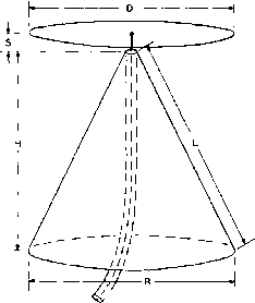 2D, IS.II. 10.6 METERS D=I2 L=I8 S= 10* R= 18 H=I5 7 /52 OHM COAXIAL FEED LINE DIMENSIONS 15.11.10,8 METERS 0=8 L=I2 S=e R=I2-HIOS 11.10,8,2 METERS 0=6 L=9e S=4 R=96 H = 83 Figure 24 DIMENSIONS OF LOW-FREQUENCY DISCONE ANTENNA FOR LOW FREQUENCY CUTOFF AT 13.2 MC, 20.1 MC, AND 26 MC Tbe Discone is a vertically polarized radiator, producirtg an omnidirectional pattern similar too ground plane. Operation on several amateur bands with low SWR on tbe co-axial feed line is possible. Additional information on L-F Discone by W2RYI in July, 1950 CQ magazine. of the radials may be reduced to 25 feet. As with all multi-band antennas that employ no lumped tuned circuits, this antenna offers no attenuation to harmonics of the transmitter. When operating on the lower frequency band, it would be wise to check the transmitter for second harmonic emission, since this antenna will effectively radiate this harmonic. The Low-Frequency Discone The discone antenna is widely used on the v-h-f bands, but until recently it has not been put to any great use on the lower frequency bands. Since the discone is a broad-band device, it may be used on several harmonically related amateur bands. Size is the limiting factor in the use of a discone, and the 20 meter band is about the lowest practical frequency for a discone of reasonable dimensions. A discone designed for 20 meter operation may be used on 20, 15, 11, Ю and
8 10 14 18 22 28 30 34 38 42 46 50 54 58 FREQUENCY (мс) Figure 25 SWR CURVE FOR A 13.2 MC DISCONE ANTENNA. SWR IS BELOW 1.5 TO 1 FROM 13.0 MC. TO 58 MC 6 meters with excellent results. It affords a good match to a 50 ohm coaxial feed system on all of these bands. A practical discone antenna is shown in figure 24, with a SWR curve for its operation over the frequency range of 13-55 Mc. shown in figure 25. The discone antenna radiates a vertically polarized wave and has a very low angle of radiation. For v-h-f work the discone is constructed of sheet metal, but for low frequency work it may be made of copper wire and aluminum angle stock. A suitable mechanical layout for a low frequency discone is shown in figure 26. Smaller versions of this antenna may be constructed for 15, 11, 10 and 6 meters, or for 11, 10, 6 and 2 meters as shown in the chart of figure 24. For minimum wind resistance, the top hat of the discone is constructed from three-quarter inch aluminum angle stock, the rods being bolted to an aluminum plate at the center of the structme. The tips of the rods are all connected together by lengths of no. 12 enamelled copper wire. The cone elements are made of no. 12 copper wire and act as guy wires for the discone structure. A very rigid arrangement may be made from this design; one that will give no trouble in high winds- A 4 x 4 post can be used to support the discone structure. The discone antenna may be fed by a length of 50-ohm coaxial cable directly from the transmitter, with a very low SWR on all bands. The Single-Wire- The old favorite single-wire-Fed Antenna fed antenna system is quite satisfactory for an impromptu all band antenna system. It is widely used for portable installations and Field Day contests where a simple, multi-band antenna is required. A single wire feeder has a characteristic impedance of some 500 ohms, de- 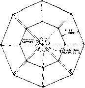 VOLTAGE CURVES .j< *NGLE STOCK TOP DtSC-TOP VIEW STEEL GUr WIRE TO EACH ELEMENT. NO INSULATORS CENTER CONDUCTOR OF Л OHM CABLE TO rtJP DISC PLATE METAL COLLAR FOf COnE WIRES JOIN ALL WIRES AND 52 OHM COAXIAL SHIELD TO COLLAR- 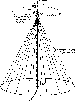 JOIN ALL WIRES AT BASE LINE 52 OHM COAXIAL LINE Figure 26 MECHANICAL CONSTRUCTION OF 20-METER DISCONE pending upon the wire size and the point of attachment to the antenna. The earth losses are comparatively low over ground of good conductivity. Since the single wire feeder radiates, it is necessary to bring it away from the antenna at right angles to the antenna wire for at least one-half the length of the antenna. The correct point for best impedance match on the fundamental frequency is not suitable for harmonic operation of the antenna. In addition, the correct length of the antenna for fundamental operation is not correct for harmonic operation. Consequently, a compromise 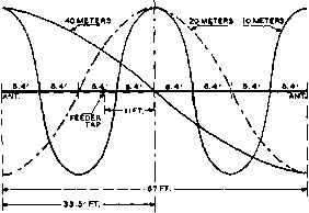 CENTER ANTENNA WrRE Figure 27 SINGLE-WIRE-FED ANTENNA FOR ALL-BAND OPERATION An antenna of this type for 40; 20 and IOmeter operation would have a radiator 67 feet long, with the feeder tapped 77 feet off center. The feeder can be 33, 66 or 99 feet long. The same type of arttenna for 80-, 40-, 20- and 10-meter operation would have a radiator 134 feet long, with the feeder tapped 22 feet off center. The feeder can be either 66 or 732 feet long. This system should be used only with those coupling methods which provide good harmonic suppression. must be made in antenna length and point of feeder connection to enable the single-wire-fed antenna to operate on more than one band. Such a compromise introduces additional reactance into the single wire feeder, and might cause loading difficulties with pi-network transmitters. To minimize this trouble, the single wire feeder should be made a multiple of 33 feet long. Two typical single-wire-fed antenna systems are shown in figure 27 with dimensions for multi-band operation. 22-8 Matching Non-Resonant Lines fo the Antenna Present practice in regard to the use of transmission lines for feeding antenna systems on the amateur bands is about equally divided HANDBOOK Matching Systems 44 3 -D--I  MATCHING SECTION NON-RESONANT LINE Figure 28 THE DELTA-MATCHED DIPOLE ANTENNA 7 he dimensions for the portions of the antenna are given in the text. transmitter end of the feed line which will change the magnitude of the standing waves on the antenna transmission line. Del to-Matched The delta type matched-im-Antenno System pedance antenna system is shown in figure 28. The impedance of the transmission line is transformed gradually into a higher value by the fanned-out Y portion of the feeders, and the Y portion is tapped on the antenna at points where the antenna impedance is a compromise between the impedance at the ends of the Y and the impedance of the unfanned portion of the line. The constants of the system are rather critical, and the antenna must resonate at the operating frequency in order to minimize standing waves on the line. Some slight readjustment of the taps on the antenna is desirable, if appreciable standing waves persist in appearing on the line. The constants for a doublet are determined by the following formulas: between three types of transmission line: (1) Ribbon or tubular molded 300-ohm line is widely used up to moderate power levels (the transmitting type is useable up to the kilowatt level). (2) Open-wire 400 to 600 ohm line is most commonly used when the antenna is some distance from the transmitter, because of the low attenuation of this type of line. (3) Coaxial line (usually RG-8/U with a 52-ohm characteristic impedance) is widely used in v-h-f work and also on the lower frequencies where the feed line must run underground or through the walls of a building. Coaxial line also is of assistance in TVI reduction since the r-f field is entirely enclosed within the line. Molded 75-ohm line is sometimes used to feed a doublet antenna, but the doublet has been largely superseded by the folded-dipole antenna fed by 300-ohm ribbon or tubular line when an antenna for a single band is required. Standing Waves As was discussed earlier, standing waves on the antenna transmission line, in the transmitting case, are a result of reflection from the point where the feed line joins the antenna system. The magnitude of the standing waves is determined by the degree of mismatch between the characteristic impedance of the transmission line and the input impedance of the antenna system. When the feed-point impedance of the antenna is resistive and of the same value as the characteristic impedance of the feed line, standing waves will not exist on the feeder. It may be well to repeat at this time that there is no adjustment which can be made at the Lfeet - Dfeet = Efeet - 467.4 megacycles megacycles 147.6 megacycles Where L is antenna length; D is the distance in from each end at which the Y taps on; E is the height of the Y section. Since these constants are correct only for a 600-ohm transmission line, the spacing S of the line must be approximately 75 times the diameter of the wire used in the transmission line. For no. 14 В & S wire, the spacing will be slightly less than 5 inches. This system should never be used on either its even or odd harmonics, as entirely different constants are required when more than a single half wavelength appears on the radiating portion of the system. Multi-Wire Doublets When a doublet antenna or the driven element in an array consists of more than one wire or tubing conductor the radiation resistance of the antenna or array is increased slightly as a result of the increase in the effective diameter of the element. Further, if we split just one h---- ® - TWIN-LEAD DRtVEN ELEMENT -iL- 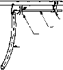 MOVEABLE CLAMP GAMMA ROD RESOKATING CONDENSER SO-70 OHM COAXIAL FEED LINE DRIVEN ELEMENT Figure 30 THE GAMMA MATCH FOR CONNECTING AN UNBALANCED COAXIAL LINE TO A BALANCED DRIVEN ELEMENT ® DRIVEN ELEMENT RESONATING X / j I-jv MATCHING SECTIC CONDENSERS  Figure 29 FOLDED-ELEMENT MATCHING SYSTEMS Drawing (A) above shows a half-wave made up to two parallel wires. If one of the wires is broken OS (П (B) and the feeder connected, the feed-point impedance is multiplied by four; such an antenna is commonly called a folded doublet. The feed-point impedance for a simple half-wave doublet fed in this manner is approximately 300 ohms, depending upon antenna height. Drawing (C) shows how the feed-point impedance can be multiplied by a factor greater than four by making the half of the element that is broken smaller in diameter than the unbroken half. An extension of the principles of (B) and (C) is the arrangement shown at (D) where the section into which the feeders are connected is considerably shorter than the driven element. This system is most convenient when the driven element is too long (such as for a 28-Mc. or 14-Mc. array) for a convenient mechanical arrangement of the system shown at (C). wire of such a radiator, as shown in figure 29, the effective feed-point resistance of the antenna or array will be increased by a factor of where N is equal to the number of conductors, all in parallel, of the same diameter in the array. Thus if there are two conductors of the same diameter in the driven element or the antenna the feed-point resistance will be multiplied by 2 or 4. If the antenna has a radiation resistance of 75 ohms its feed-point resistance will be 300 ohms, this is the case of the conventional folded-dipole as shown in figure 29B. If three wires are used in the driven radiator the feed-point resistance is increased by a factor of 9; if four wires are used the impedance is increased by a factor of 16, and so on. In certain cases when feeding a parasitic array it is desirable to have an impedance step up different from the value of 4:1 obtained with two elements of the same diameter and 9:1 with three elements of the same diameter. Intermediate values of impedance step up maybe obtained by using two elements of different diameter for the complete driven element as shown in figure 29C. If the conductor that is broken for the feeder is of smaller diameter than the other conductor of the radiator, the impedance step up will be greater than 4:1. On the other hand if the larger of the two elements is broken for the feeder the impedance step up will be less than 4:1. The T Match A method of matching a balanced low-impedance transmission line to the driven element of a parasitic array is the T match illustrated in figure 29D. This method is an adaptation of the multi-wire doublet principle which is more practicable for lower-frequency parasitic arrays such as those for use on the 14-Mc. and 28-Mc. bands. In the system a section of tubing of approximately one-half the diameter of the driven element is spaced about four inches below the driven element by means of clamps which hold the T-section mechanically and which make electrical connection to the driven element. The length of the T-section is normally between 15 and 30 inches each side of the center of the dipole for transmission lines of 300 to 600 ohms impedance, assuming 28-Mc. operation. In series with each leg of the T-section and the transmission line is a series resonating capacitor. These two capacitors tune out the reactance of the T- section. If they are not used, the T-section will detune the dipole when the T-section is attached to it. The two capacitors may be ganged together, and once adjusted for minimum detuning action, they may be locked. A suitable housing should be devised to protect these capacitors from the weather. Additional information on the adjustment of the T-match is given in the chapter covering rotary beam antennas. The Gommo Match An unbalanced version of the T-match may be used to feed a dipole from an unbalanced coaxial line. Such a device is called a Gamma Match, and is illustrated in figure 30. The length of the Gamma rod and the spacing of it from the dipole determine the impedance level at the transmission line end of the rod. The series capacitor is used to tune out the reactance introduced into the system by the Gamma rod. The adjustment of the Gamma Match is discussed in the chapter covering rotary beam antennas. Matching Stubs By connecting a resonant section of transmission line (called a matching stub) to either a voltage or current loop and attaching parallel-wire non-resonant feeders to the resonant stub at a suitable voltage (impedance) point, standing waves on the line may be virtually eliminated. The stub is made to serve as an auto-transformer. Stubs are particularly adapted to matching an open line to certain directional arrays, as will be described later. Voltage Feed %Ъеп the stub attaches to the antenna at a voltage loop, the stub should be a quarter wavelength long electrically, and be shorted at the bottom end. The stub can be resonated by sliding the shorting bar up and down before the non-resonant feeders are attached to the stub, the antenna being shock-excited from a separate radiator during the process. Slight errors in the length of the radiator can be compensated for by adjustment of the stub if both sides of the stub are connected to the radiator in a symmetrical manner. Where only one side of the stub connects to the radiating system, as in the Zepp and in certain antenna arrays, the radiator length must be exactly right in order to prevent excessive unbalance in the untuned line. A dial lamp may be placed in the center of the shorting stub to act as an r-f indicator. Current Feed When a stub is used to current-feed a radiator, the stub should either be left open at the bottom end instead of shorted, or else made a half wave long. - ANTENNA- -ac - l-STUB IV.. NON-1 ® RESONANT EDERS SHORTING BAR - ANTENNA- SHORTING BAR- -aCB- STUB ®  NON-RaWlANT ANTENNA NON-RESONANT FEEDERS  OPEN -ecs- FEEDER TAPS NEAR END OF STUB STUB NON-RESONANT. FEEDER, STUB )Af ~ SHORTlh Figure 31 MATCHING-STUB APPLICATIONS An end-fed half-wave antenna with a quarter-wave shorted stub is shown at (A). (B) shows the use of a half-wave shorted stub to feed a relatively low impedance point such as the center of the driven element of a parasitic array, or the center of a half-wave dipole. The use of an open-ended quarter-wave stub to feed a low impedance is illustrated at (C). (D) shows the conventional use of a shorted quarter-wave stub to voltage feed two half-wave anfennas with a 180° phase difference. The open stub should be resonated in the same manner as the shorted stub before attaching the transmission line; however, in this case, it is necessary to prune the stub to resonance, as there is no shorting bar. Sometimes it is handy to have a stub hang from the radiator to a point that can be reached from the ground, in order to facilitate adjustment of the position of the transmission-line attachment. For this reason, a quarter-wave stub is sometimes made three-quarters wavelength long at the higher frequencies, in order to bring the bottom nearer the ground. Operation with any odd number of quarter waves is the same as for a quarter-wave stub. Any number of half waves can be added to either a quarter-wave stub or a half-wave stub without disturbing the operation, though losses and frequency sensitivity will be lowest if the shortest usable stub is employed. See figure 31.
Linear R-F A resonant quarter-wave line Tronsformers has the unusual property of acting much as a transformer. Let us take, for example, a section consisting of no. 12 wire spaced 6 inches, which happens to have a surge impedance of 600 ohms. Let the far end be terminated with a pure resistance, and let the near end be fed with radio-frequency energy at the frequency for which the line is a quarter wavelength long. If an impedance measuring set is used to measure the impedance at the near end while the impedance at the far end is varied, an interesting relationship between the 600-ohm characteristic surge impedance of this particular quarter-wave matching line, and the impedance at the ends will be discovered. Uben the impedance at the far end of the line is the same as the characteristic surge impedance of the line itself (600 ohms), the impedance measured at the near end of the quarter-wave line will also be found to be 600 ohms. Under these conditions, the line would not have any standing waves on it, since it is terminated in its characteristic impedance. Now, let the resistance at the far end of the line be doubled, or changed to 1200 ohms. The impedance measured at the near end of the line will be found to have been cut in half, to 300 ohms. If the resistance at the far end is made half the original value of 600 ohms or 300 ohms, the impedance at the near end doubles the original value of 600 ohms, and becomes 1200 ohms. As one resistance goes up, the other goes down proportionately. It will always be found that the characteristic surge impedance of the quarter-wave matching line is the geometric mean between the impedance at both ends. This relationship is shown by the following formula: Zms - vZaZl where Zs - Impedance of matching section. Za = Antenna resistance. Zl - Line impedance. Quarter-Wave The impedance inverting char-Matching acteristic of a quarter-wave Transformers section of transmission line is widely used by making such a section of line act as a quarter-wave transformer. The Johnson Q feed system is a widely known application of the quarter-wave transformer to the feeding of a dipole antenna and array consisting of two dipoles. However, the quarter-wave transformer may be used in a wide number of applications wherever a transformer is required to match two impedances whose geometric mean is somewhere between perhaps 25 and 750 ohms when transmission line sections can be used. Paralleled coaxial lines may be used to obtain the lowest impedance mentioned, and open-wire lines composed of small conductors spaced a moderate distance may be used to obtain the higher impedance. A short list of impedances, which may be matched by quarter-wave sections of transmission line having specified impedances, is given below.
Johnson-Q The standard form of Johnson- Feed System Q feed to a doublet is shown in figure 32. An impedance match is obtained by utilizing a matching section, the surge impedance of which is the geometric mean between the transmission line surge impedance and the radiation resistance of the radiator. A sufficiently good match usu- HANDBOOK Matching Systems 447 tubing - 234 f(MC) Q MATCHING SECTION UNTUNED LINE ANY LENGTH Figure 32 HALF-WAVE RADIATOR FED BY Q BARS The Q watching section is simply о quarter-wave transformer whose impedance is equal to the geometric mean between the impedance at tbe center of the antenna and the impedance of the transmission line to be used to feed the bottom of the transformer. The transformer may be made up of parallel tubing, a four-wire line, or any other type of transmission line which has the correct value of impedance. ally can be obtained by either designing or adjusting the matching section for a dipole to have a surge impedance that is the geometric mean between the line impedance and 72 ohms, the latter being the theoretical radiation resistance of a half-wave doublet either infinitely high or a half wave above a perfect ground. Though the radiation resistance may depart somewhat from 72 ohms under actual conditions, satisfactory results will be obtained with this assumed value, so long as the dipole radiator is more than a quarter wave above effective earth, and reasonably in the clear. The small degree of standing waves introduced by a slight mismatch will not increase the line losses appreciably, and any small amount of reactance present can be tuned out at the transmitter termination with no bad effects. If the reactance is objectionable, it may be minimized by making the untuned line an integral number of quarter waves long. A Q-matched system can be adjusted precisely, if desired, by constructing a matching section to the calculated dimensions with provision for varying the spacing of the Q section conductors slightly, after the untuned line has been checked for standing waves.
PARALLEL TUBING SURGE IMPEDANCE FOR MATCHING SECTIONS The Collins The advantage of unbal- Transmission Line anced output networks Matching System for transmitters are nu- merous; however this output system becomes awkward when it is desired to feed an antenna system utilizing a balanced input. For some time the Collins Radio Co. has been experimenting with a bal-un and tapered line system for matching a coaxial output transmitter to an open-wire balanced transmission line. Considerable success has been obtained and matching systems good over a frequency range as great as four to one have been developed. Illustrated in figure 33 is one type of matching system which is proving satisfactory over this range. Zj is the transmitter end of the system and may be any length of 52-ohm coaxial cable. is one-quarter wavelength long at the mid-frequency of the range to be covered and is made of 75 ohm coaxial cable. Z\ is a quarter-wavelength shorted section of cable at the mid-frequency. Zo (Za and Zj) forms a 200-ohm quarter-wave section. The Za section is formed of a conductor of the same diameter as Zj. The difference in length between Za and Zj is accounted for by the fact that Zj is a coaxial conductor with a solid dielectric, whereas the dielectric for Zo is air. Z3 is one-quarter wavelength long at the mid-frequency and has an imped- INNER 8 OUTER CONDUCTORS SHORTED AT EACH END Figure 33 COLLINS TRANSMISSION LINE MATCHING SYSTEM A wide-band sysfem for matching a 52-ohm coaxial line to a balanced 300-ohm line over a 4:1 wide frequency range. ance of 123 ohms. Z4 is one-quarter wavelength long at the mid-frequency and has an impedance of 224 ohms. Z5 is the balanced line to be matched (in this case ЗОО ohms) and may be any length. Other system parameters for different output and input impedances may be calculated from the following: Transformation ratio (r) for each section is: Where N is the number of sections. In the above case, Impedance between sections, as Z2-3, is r times the preceding section. Zj., = r X Z and Z,., = r X Zj.,. Mid-frequency (m): F, +F, m = - 7+30 For 40-20-10 meters =-= 18.5 Mc. and one-quarter wavelength = 12 feet. 17 -in ,л 14 + 54 ror 20-10-6 meters - - 34 j. and one-quarter wavelength 5.5 feet. The impedances of the sections are: Z, = V Z. к Z,.3 Z3 = V Zj.3 X Z3.4 Z., V Z3.4 X Z5 Zo = % X Z, Generally, the larger number of taper sections the greater will be the bandwidth of the system. 22-9 Antenno Construction The foregoing portion of this chapter has been concerned primarily with the electrical characteristics and considerations of antennas. Some of the physical aspects and mechanical problems incident to the actual erection of antennas and arrays will be discussed in the following section. Up to 60 feet, there is little point in using mast-type antenna supports unless guy wires either must be eliminated or kept to a minimum. While a little more difficult to erect, because of their floppy nature, fabricated wood poles of the type to be described will be just as satisfactory as more rigid types, provided many guy wires are used. Rather expensive when purchased through the regular channels, 40- and 50-foot telephone poles sometimes can be obtained quite reasonably. In the latter case, they are hard to beat, inasmuch as they require no guying if set in the ground six feet (standard depth), and the resultant pull in any lateral direction is not in excess of a hundred pounds or so. For heights of 80 to 100 feet, either three-sided or four-sided lattice type masts are most practicable. They can be made self-supporting, but a few guys will enable one to use a smaller cross section without danger from high winds. The torque exerted on the base of a high self-supporting mast is terrific during a strong wind. The A-Frame Figures 34A and 34B show Mast the standard method of con- struction of the A-frame type of mast. This type of mast is quite frequently used since there is only a moderate amount of work involved in the construction of the assembly and since the material cost is relatively small. The three pieces of selected 2 by 2 are first set up on three sawhorses or boxes and the holes drilled for the three Ы-inch bolts through the center of the assembly. Then the base legs are spread out to about 6 feet and the bottom braces installed. Then the upper braces and the cross pieces are installed and the assembly given several coats of good-quality paint as a protection against weathering. Figure 34c shows another common type of mast which is made up of sections of 2 by 4 placed end-to-end with stiffening sections of 1 by 6 bolted to the edge of the 2 by 4 sections. Both types of masts will require a set of top guys and another set of guys about one-third of the way down from the top. Two guys spaced about 90 to 100 degrees and pulling against the load of the antenna will normally be adequate for the top guys. Three guys are usually used at the lower level, with one directly behind the load of the antenna and two more spaced 120 degrees from the rear guy. The raising of the mast is made much easier HANDBOOK Antenna Construction 449 Figure 34 TWO SIMPLE WOOD MASTS Shown ot (A) is the method of assembly, and at (B) is the completed structure, of the conventional A-frame antenna mast. At (C) Is shown о structure wh/ch is heovier but more stable than the A-frame for heights above about 40 feet. -20 2X2 3 bolts 2 lap sawhorses 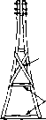 brace cRossptecES / BOLTS 1X8 eROUNO level i i J 1 ]Г comcrete;! s- ® © if a gin pole about 20 feet high is installed about 30 or 40 feet to the rear of the direction in which the anteima is to be raised. A line from a pulley on the top of the gin pole is then tun to the top of the pole to be raised. The gin pole comes into play when the center of the mast has been raised 10 to 20 feet above the ground and an additional elevated pull is required to keep the top of the mast coming up as the center is raised further above ground. Using TV Mosts Steel tubing masts of the telescoping variety are widely available at a moderate price for use in supporting television antenna arrays. These masts usually consist of several 10-foot lengths of electrical metal tubing (EMT) of sizes such that the sections will telescope. The 30-foot and 40-foot lengths are well suited as masts for supporting antennas and arrays of the types used on the amateur bands. The masts are constructed in such a manner that the bottom 10-foot length may be guyed permanently before the other sections are raised. Then the upper sections may be extended, beginning with the top-mast section, until the mast is at full length (provided a strong wind is not blowing) following which all the guys may be anchored. It is important that there be no load on the top of the mast when the vertical raising method is to be employed. Guy Wires Guy wires should never be pulled taut; a small amount of slack is desirable. Galvanized wire, somewhat heavier than seems sufficient for the job, should be used. The heavier wire is a little harder to handle, but costs only a little more and takes longer to rust through. Care should be taken to make sure that no kinks exist when the pole or tower is ready for erection, as the wire will be greatly weakened at such points if a kink is pulled tight, even if it is later straightened. If dead men are used for the guy wire terminations, the wire or rod reaching from the dead men to the surface should be of non-rusting material, such as brass, or given a heavy coating of asphalt or other protective substance to prevent destructive action by the damp soil. Galvanized iron wire will last only a short time when buried in moist soil. Only strain-type (compression) insulators should be used for guy wires. Regular ones might be sufficiently strong for the job, but it is not worth taking chances, and egg-type strain halyard insulators are no more expensive. Only a brass or bronze pulley should be used for the halyard, as a high pole with a rusted pulley is truly a sad affair. The bearing of the pulley should be given a few drops of heavy machine oil before the pole or tower is raised. The halyard itself should be of good material, preferably water-proofed. Hemp rope of good quality is better than window sash cord from several standpoints, and is less expensive. Soaking it thoroughly in engine oil of medium viscosity, and then wiping it off with a rag, will not only extend its life but minimize shrinkage in wet weather. Because of the difficulty of replacing a broken halyard it is a good idea to replace it periodically, without waiting for it to show excessive wear or deterioration. It is an excellent idea to tie both ends of the halyard line together in the manner of a flag-pole line. Then the antenna is tied onto the place where the two ends of the halyard are joined. This procedure of making the halyard into a loop prevents losing the top end of the halyard should the antenna break near the end, and it also prevents losing the halyard completely should the end of the halyard carelessly be allowed to go free and be pulled through the pulley at the top of the mast by the antenna load. A somewhat longer piece of line is required but the insurance is well worth the cost of the additional length of rope. Trees as Often a tall tree can be called up-Supports on to support one end of an antenna, but one should not attempt to attach anything to the top, as the swaying of the top of the tree during a heavy wind will complicate matters. If a tree is utilized for support, provision should be made for keeping the antenna taut without submitting it to the possibility of being severed during a heavy wind. This can be done by the simple expedient of using a pulley and halyard, with weights attached to the lower end of the halyard to keep the antenna taut. Only enough weight to avoid excessive sag in the antenna should be tied to the halyard, as the continual swaying of the tree submits the pulley and halyard to considerable wear. Galvanized iron pipe, or steel-tube conduit, is often used as a vertical radiator, and is quite satisfactory for the рифозе. However, when used for supporting antennas, it should be remembered that the grounded supporting poles will distort the field pattern of a vertically polarized antenna unless spaced some distance from the radiating portion. Painting The life of a wood mast or pole can be increased several hundred per cent by protecting it from the elements with a coat or two of paint. And, of course, the appearance is greatly enhanced. The wood should first be given a primer coat of flat white outside house paint, which can be thinned down a bit to advantage with second-grade linseed oil. For the second coat, which should not be applied until the first is thoroughly dry, aluminum paint is not only the best from a preservative standpoint, but looks very well. This type of paint, when purchased in quantities, is considerably cheaper than might be gathered from the price asked for quarter-pint cans. Portions of posts or poles below the surface of the soil can be protected from termites and moisture by painting with creosote. While not so strong initially, redwood will deteriorate much more slowly when buried than will the white woods, sudi as pine. Antenna Wire The antenna or array itself presents no especial problem. A few considerations should be borne in mind, however. For instance, soft-drawn copper should not be used, as even a short span will stretch several per cent after whipping around in the wind a few weeks, thus affecting the resonant frequency. Enameled-copper wire, as ordinarily available at radio stores, is us-ally soft drawn, but by tying one end to some object such as a telephone pole and the other to the frame of an auto, a few husky tugs can be given and the wire, after stretching a bit, is equivalent to hard drawn. Where a long span of wire is required, or where heavy insulators in the center of the span result in considerable tension, copper-clad steel wire is somewhat better than hard-drawn copper. It is a bit more expensive, though the cost is far from prohibitive. The use of such wire, in conjunction with strain insulators, is advisable, where the antenna would endanger persons or property should it break. For transmission lines and tuning stubs steel-core or hard-drawn wire will prove awkward to handle, and soft-drawn copper should, therefore, be used. If the line is long, the strain can be eased by supporting it at several points. More important from an electrical standpoint than the actual size of wire used is the soldering of joints, especially at current loops in an antenna of low radiation resistance. In fact, it is good practice to solder all joints, thus insuring quiet operation when the antenna is used for receiving. Insulation A question that often arises is that of insulation. It depends, of course, upon the r-f voltage at the point at which the insulator is placed. The r-f voltage, in turn, depends upon the distance from a current node, and the radiation resistance of the antenna. Radiators having low radiation resistance have very high voltage at the voltage loops; consequently, better than usual insulation is advisable at those points. Open-wire lines operated as non-resonant lines have little voltage across them; hence the most inexpensive ceramic types are sufficiently good electrically. With tuned lines, the voltage depends upon the amplitude of the standing waves. If they are very great, the voltage will reach high values at the voltage loops, and the best spacers available are none too good. At the current loops the voltage is quite low, and almost anything will suffice. 1 ... 41 42 43 44 45 46 47 ... 80 |
|||||||||||||||||||||||||||||||||||||||||||||||||||||||||||||||||||||||||||||||||||||||||||||||||||||||||||||||||||||||||||||||||||||||||||||||||||||||||||||||||||
|
© 2026 AutoElektrix.ru
Частичное копирование материалов разрешено при условии активной ссылки |