 |
 |
 |
| Главная Журналы Популярное Audi - почему их так назвали? Как появилась марка Bmw? Откуда появился Lexus? Достижения и устремления Mercedes-Benz Первые модели Chevrolet Электромобиль Nissan Leaf |
Главная » Журналы » Simple coaxial reflectometer 1 ... 42 43 44 45 46 47 48 ... 80 HANDBOOK Antenna Coupling Systems 451 When insulators are subject to very high r-f voltages, they should be cleaned occasionally if in the vicinity of sea water or smoke. Salt scum and soot are not readily dislodged by rain, and when the coating becomes heavy enough, the efficiency of the insulators is greatly impaired. If a very pretentious installation is to be made, it is wise to check up on both underwriters rules and local ordinances which might be applicable. If you live anywhere near an airport, and are contemplating a tall pole, it is best to investigate possible regulations and ordinances pertaining to towers in the district, before starting construction. 22-10 Coupling to the Antenna System When coupling an antenna feed system to a transmitter the most important considerations are as follows: (1) means should be provided for varying the load on the amplifier; (2) the two tubes in a push-pull amplifier should be equally loaded; (3) the load presented to the final amplifier should be resistive (non-reactive) in character; and (4) means should be provided to reduce harmonic coupling between the final amplifier plate tank circuit and the antetma or antenna transmission line to an extremely low value. The Transmitter- The problem of coupling the Loading Problem power output of a high-frequency or v-h-f transmitter to the radiating portion of the antenna system has been materially complicated by the virtual necessity for eliminating interference to TV reception. However, the TVI-elimination portion of the problem may always be accomplished by adequate shielding of the transmitter, by filtering of the control and power leads which enter the transmitter enclosure, and by the inclusion of a harmonic-attenuating filter be- tween the output of the transmitter and the antenna system. Although TVI may be eliminated through inclusion of a filter between the output of a shielded transmitter and the antenna system, the fact that such a filter must be included in the link between transmitter and antenna makes it necessary that the transmitter-loading problem be re-evaluated in terms of the necessity for inclusion of such a filter. Harmonic-attenuating filters must be operated at an impedance level which is close to their design value; therefore they must operate into a resistive termination substantially equal to the characteristic impedance of the filter. If such filters are operated into an impedance which is not resistive and approximately equal to their characteristic impedance: (1) the capacitors used in the filter sections will be subjected to high peak voltages and may be damaged, (2) the harmonic-attenuating properties of the filter will be decreased, and (3) the impedance at the input end of the filter will be different from that seen by the filter at the load end (except in the case of the half-wave type of filter). It is therefore important that the filter be included in the transmitter-to-antenna circuit at a point where the impedance is close to the nominal value of the filter, and at a point where this impedance is likely to remain fairly constant with variations in frequency. Block Diagrams of Transmitter-to-Antenna Coupling Systems transmitter-to-antenna There are two basic arrangements which include all the provisions required in the coupling system, and which permit the harmonic-attenuating filter to be placed at a position in the coupling system where it can be operated at an impedance level close to its nominal value. These arrangements are illustrated in block-diagram form in figures 35 and 36. The arrangement of figure 35 is recommended for use with a single-band antenna system, such as a dipole or a rotatable array, wherein an impedance matching system is included iHIELD AT TRANSMITTER
COUPLINS AOJUSTMENTi LijHARMONIC SVrrENUATIN I SYSTEM AT ANTENNA matching 1=- ]at antenna! I SYSTEM Figure 35 ANTENNA COUPLING SYSTEM The harmonic suppressing antenna coupling system illustrated above is for use w no transmission line has a low standing-wave ratio, and when the characteristic the antenna transmission line is the same as the nominal impedance of the low-p attenuating filter. when the anten-impedance of pass harmonic- г shiel2 at transmitter at antenna
HARMONIC i=ATTENUATIh Yl SYSTEM antenna L coupler г- [impedance 1 [ ---------matching transmission lat antenna line - RADIATING SYSTEM Figure 36 ANTENNA COUPLING SYSTEM The antenna coupling system illustrated above is for use when the antenna transmission line does not have the same characteristic impedance as the TVI filter, and when the standing-wave ratio on the anfenna fransm/ss/on line may or may not be low. within or adjacent to the antenna. The feed line coming down from the antenna system should have a characteristic impedance equal to the nominal impedance of the harmonic filter, and the impedance matching at the antenna should be such that the standing-wave ratio on the antenna feed line is less than 2 to 1 over the range of frequency to be fed to the antenna. Such an arrangement may be used with open-wire line, ribbon or tubular line, or with coaxial cable. The use of coaxial cable is to be recommended, but in any event the impedance of the antenna transmission line should be the same as the nominal impedance of the harmonic filter. The arrangement of figure 35 is more or less standard for commercially manufactured equipment for amateur and commercial use in the h-f and v-h-f range. The arrangement of figure 36 merely adds an antenna coupler between the output of the harmonic attenuating filter and the antenna transmission line. The antenna coupler will have some harmonic-attenuating action, but its main function is to transform the impedance at the station end of the antenna transmission line to the nominal value of the harmonic filter. Hence the arrangement of figure 36 is more general than the figure 35 system, since the inclusion of the antenna coupler allows the system to feed an antenna transmission line of any reasonable impedance value, and also without regard to the standing-wave ratio which might exist on the antenna transmission line. Antenna couplers are discussed in a following section. Output Coupling Adjustment It will be noticed by reference to both figure 35 and figure 36 that a box labeled Coupling Adjustment is included in the block diagram. Such an element is necessary in the complete system to afford an adjustment in the value of load impedance presented to the tubes in the final amplifier stage of the transmitter. The impedance at the input terminal of the harmonic filter is established by the antenna, through its matching system and the antenna coupler, if used. In any event the impedance at the input terminal of the harmonic filter should be very close to the nominal impedance of the filter. Then the Coupling Adjustment provides means for transforming this impedance value to the correct operating value of load impedance which should be presented to the final amplifier stage. There are two common ways for accomplishing the antenna coupling adjustment, as illustrated in figures 37 and 38. Figure 37 shows the variable-link arrangement most commonly used in home-constructed equipment, while the pi-netowrk coupling arrangement commonly used in commercial equipment is illustrated in figure 38. Either method may be used, and each has its advantages. Variable-Link The variable-link method il-Coupling lustrated in figure 37 has the advantage that standard manufactured components may be used with no changes. However, for greatest bandwidth of operation of the coupling circuit, the reactance of the link coil, L, and the reactance of the link tuning capacitor, C, should both be between 3 and 4 times the nominal load impedance of the harmonic filter. This is to say that the inductive reactance of the coupling link L should be tuned out or resonated by capacitor C, and the operating Q of the L-C link circuit should be between 3 and 4. If the link coil is not variable with respect to the tank coil of the final amplifier, capacitor С may be used as a loading control; however, this system is not recommended since its use will require adjustment of С whenever a frequency change is made at the transmitter. If L and С are made resonant at the center of a band, with a link circuit Q of 3 to 4, and coupling adjustment is made by physical adjustment of L with respect to the final amplifier tank coil, it usually will be possible to operate over an entire amateur band without change in the coupling system. Capacitor С normally may have a low voltage rating, even with a high power transmitter, due to the low Q and low impedance of the coupling circuit. HANDBOOK Pi-Network Coupling Systems 453 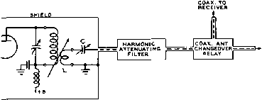 TO ANTENNA FEEDLINE OR TO ANTENNA COUPLER Figure 37 TUNED-LINK OUTPUT CIRCUIT Copociror С should be adjusted so as to tun out the inductive reactance of the eoupting link, L. Loading of the amplifier then Is varied by physlcallY varying the coupling between the plate tank of the final amplifier and the antenna coupling fink, Pi-Neiwork The pi-network coupling system Coupling offers two advantages: (1) a tne-chant cal coupling variation is not required to vary the loading of the final amplifier, and (2) the pi network (if used with an operating Q of about 15) offers within itself a harmonic attenuation of 40 db or more, in addition to the harmonic attenuation provided by the additional harmonic attenuating filter. Some commercial equipments (such as the Collins amateur transmitters) 1псофогаге an L network in addition to the pi network, for accomplishing the impedance transformation in two steps and to provide additional harmonic attenuation. Tuning the Pi-Section Coupler Tuning of a pi-network coupling circuit such as illustrated in figure 38 is accomplished in the following manner: First remove the connection between the оифи1 of the amplifier and the harmonic filter (load). Tune Cj to a capacitance which is large for the band in use, adding suitable additional ca- pacitance by switch S if operation is to be on one of the lower frequency bands. Apply reduced plate voltage to the stage and dip to resonance with C,. It may be necessary to vary the inductance in coil L, but in any event resonance should be reached with a setting of Ci which is approximately correct for the desired value of operating Q of the pi network. Next, couple the load to the amplifier (through the harmonic filter), apply reduced plate voltage again and dip to resonance with C,. If the plate current dip with load is too low (taking into consideration the reduced plate voltage), decrease the capacitance of Cj and again dip to resonance, repeating the procedure until the correct value of plate current is obtained with full plate voltage on the stage-There should be a relatively small change required in the setting of Ci (from the original setting of Cj without load) if the operating Q of the network is correct and if a large value of impedance transformation is being employed-as would be the case when transforming from the plate impedance of a single- COAX TO RECEIVER SHIELD lAXclic HARMONIC ATTENUATING FILTER COAXIAL ANTENNA CHANGEOVER RELAY TO FEEDLINE EJOR ANTENNA COUPLER Figure 38 PI-NETWORK ANTENNA COUPLER The design of pl-network output circuits is discussed in Chapter Thirteen. The additional output-end shur)i!ng capaciiors selected by switch S are for use on the Tower frequency ranges. Inductor L may be selected by a tap switch, it may be continuously variable, or plug-in inductors may be used. 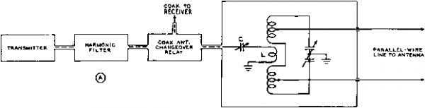 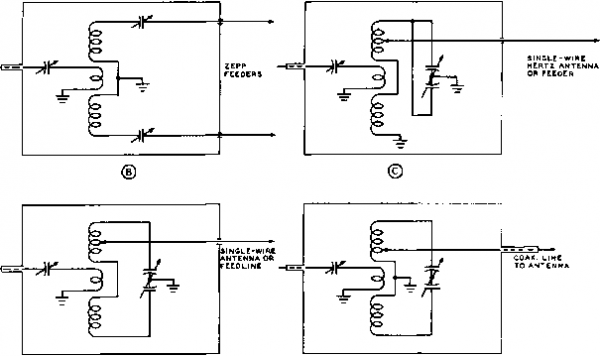 ® Figure 39 ALTERNATIVE ANTENNA-COUPLER CIRCUITS Plug-in calls, one or two variable capacitors of the split-stator variety, and a system of switches or plugs and jacks may be used in the antenna coupler to accomplish the feeding of different types of antennas and antenna transmission lines from the coaxial input line from the transmitter or from the anfenna changeover relay. Link L should be resonated with capacitor С at the operating frequency of the transmitter so that the harmonic filter will operate Into a resistive load impedance of the correct nominal value. ended output stage down to the 50-ohm impedance of the usual harmonic filter and its subsequent load. In a pi network of this type the harmonic attenuation of the section will be adequate when the correct value of and L are being used and when the resonant dip in is sharp. If the dip in Cj is broad, or if the plate current persists in being too high with Q at maximum setting, it means that a greater value of capacitance is required at Cj, assuming that the values of Cj and L are correct. 22-n Antenna Couplers As stated in the previous section, an antenna coupler is not required when the impedance of the antenna transmission line is the same as the nominal impedance of the harmonic fil- HANDBOOK Antenna Couplers 455 ter, assuming that the antenna feed line is being operated with a low standing-wave ratio. However, there are many cases where it is desirable to feed a multi-band antenna from the output of the harmonic filter, where a tuned line is being used to feed the antenna, or where a long wire without a separate feed line is to be fed from the output of the harmonic filter. In such cases an antenna coupler is required. Some harmonic attenuation will be provided by the anteIшa coupler, particularly if it is well shielded. In certain cases when a pi network is being used at the output of the transmitter, the addition of a shielded antenna coupler will provide sufficient harmonic attenuation. But in all normal cases it will be necessary to include a harmonic filter between the output of the transmitter and the antenna coupler. When an adequate harmonic filter is being used, it will not be necessary in normal cases to shield the antenna coupler, except from the standpoint of safety or convenience. Function of on The function of the antenna Antenna Coupler coupler is, basically, to transform the impedance of the antenna system being used to the correct value of resistive impedance for the harmonic filter, and hence for the transmitter. Thus the antenna coupler may be used to resonate the feeders or the radiating portion of the antenna system, in addition to its function of impedance transformation. It is important to remember that there is nothing that can be done at the antenna coupler which will eliminate standing waves on the antenna transmission line. Standing waves are the result of reflection from the antenna, and the coupler can do nothing about this condition. However, the antenna coupler can resonate the feed line (by introducing a conjugate impedance) in addition to providing an impedance transformation. Thus, a resistive impedance of the correct value can be presented to the harmonic filter, as in figure 36, regardless of any reasonable value of standing-wave ratio on the antenna transmission line. Types of All usual types of antenna Antenna Couplers couplers fall into two classifications: (1) inductively coupled resonant systems as exemplified by those shown in figure 39, and (2) conductively coupled pi-network systems such as shown in figure 40. The inductively-coupled system is much more commonly used, since it is convenient for feeding a balanced line from the coaxial output of the usual harmonic filter. The pi-network system is most useful for feeding a length of wire from the output of a transmitter. COAX. TO RECEIVER SINGLE WIRE ANTENNA transmitterLJ harmonic П n 1 COAX. ANT. I CHANGEOVER RELAY I Figure 40 PI-NETWORK ANTENNA COUPLER An arrangement such as iHustrated above is convenient for feeding an end-fed Hertz antenna, or a random length of wire for portable or emergency operation, from the nominal volue of impedance of the harmonic filter. Several general methods for using the inductively-coupled resonant type of antenna coupler are illustrated in figure 39- The coupling between the link coil L and the main tuned circuit need not be variable; in fact it is preferable that the correct link size and placement be determined for the tank coil which will be used for each band, and then that the link be made a portion of the plug-in coil. Capacitor С then can be adjusted to a pre-determined value for each band such that it will resonate with the link coil for that band. The reactance of the link coil (and hence the reactance of the capacitor setting which will resonate the coil) should be about 3 or 4 times the impedance of the transmission line between the aiitenna coupler and the harmonic filter, so that the link coupling circuit will have an operating Q of 3 or 4. The use of capacitor С to resonate with the inductance of the link coil L will make it easier to provide a low standing-wave ratio to the output of the harmonic filter, simply by adjustment of the antenna-coupler tank circuit to resonance. If this capacitor is not included, the system still will operate satisfactorily, but the tank circuit will have to be detuned slightly from resonance so as to cancel the inductive reactance of the coupling link and thus provide a resistive load to the output of the harmonic filter. Variations in the loading of the final amplifier should be made by the coupling adjustment at the final amplifier, not at the antenna coupler. The pi-network type of antenna coupler, as shown in figure 40 is useful for certain applications, but is primarily useful in feeding a single-wire antenna from a low-impedance transmission line. In such an application the operating Q of the pi network may be somewhat lower than that of a pi network in the plate circuit of the final amplifier of a transmitter, as shown in figure 38. An operating Q of 3 or 4 PARALLEL-WIRE TO 40-60 M< ANTENNA TO COAX. LINES TO RECEIVER IOM.ANT гОМ.АыТ 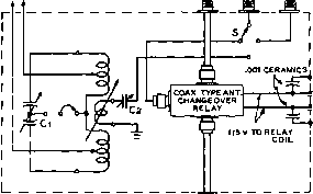 3IN(sle wire ANTENNA TRANSMITTER THROUGH HARMONIC FILTER Figure 41 ALTERNATIVE COAXIAL ANTENNA COUPLER This circuit IS гесоттепс/е(У not only as being most desirable when coaxial lines with low s.w.r, ore being used to feed antenna systems such as rotatable beams, but when it also is desired to feed through open-wire line to some sort of multi-band antenna for the lower frequency ranges. The tuned circuit of the antenna coupler is operative only when using the open-wire feed, and then It ts in operation both for transmit and receive. in such an application will be found to be adequate, since harmonic attenuation has been accomplished ahead of the antenna coupler. However, the circuit will be easier to tune* although it will not have as great a bandwidth, if the operating Q is made higher. An alternative arrangement shown in figure 4l utilizes the antenna coupling tank circuit only when feeding the coaxial output of the transmitter to the open-wire feed line (or similar multi-band antenna) of the 40- 80 meter antenna. The coaxial lines to the 10-meter beam and to the 20-meter beam would be fed directly from the output of the coaxial antenna changeover relay through switch S. 22-12 A Single-Wire Antenna Tuner One of the simplest and least expensive antennas for transmission and reeeption is the single wire, end-fed Hertz antenna. When used over a wide range of frequencies, this type of antenna exhibits a very great range of input impedance. At the low frequency end of the spectrum such an antenna may present a resistive load of less than one ohm to the transmitter, combined with a large positive or negative value of reactance. As the frequency of operation is raised, the resistive load may 52 л COAXIAL LINE -ff= FROM -<p XMTH I SWR INDICATOR Figure 42 ANTENNA TUNER AND SWR INDICATOR FOR RANDOM LENGTH HERTZ ANTENNA rise to several thousand ohms (near half-wave resonance) and the reactive component of the load can rapidly change from positive to negative values, or vice-versa. It is possible to match a 52-ohm transmission line to such an antenna at almost any frequency between 1.8 mc and 30 mc widi the use of a simple tuner of the type shown in figure 42. A variable series inductor L, and a variable shunt capacitor Cl permit circuit resonance and impedance transformation to be established for most antenna lengths. Switch Si permits the selection of series capacitor С for those instances when the single wire antenna exhibits large values of positive reactance. To provide indication for the tuning of the network, a radio frequency bridge (SWR meter) is included to indicate the degree of mismatch (standing wave ratio) existing at the input to the tuner. All adjustments to the tuner are made with the purpose of reaching unity standing wave ratio on the coaxial feed system between the tuner and the transmitter. A Proctical A simple antenna tuner for Antenna Tuner use with transmitters of 250 watts power or less is shown in figures 43 through 46. A SWR bridge circuit is used to indicate tuner resonance. The resistive arm of the bridge consists of ten 10-ohm, 1-watt carbon resistors connected in parallel to form a 1-ohm resistor (Rl). The other pair of bridge arms are capacitive rather than resistive. The bridge detector is a simple r-f voltmeter employing a IN56 crystal diode and a 0-1 d.c. milliammeter. A sensitivity control is incorporated to prevent overloading the meter when power is first applied to the tuner. Final adjustments are made with the sensitivity control at its maxi- HANDBOOK Single-wire Antenna Tuner 457  Figure 43 ANTENNA TUNER IS HOUSED IN METAL CABINET 7 x 8 IN SIZE. 52 Cl input from xmtr R, jjj ]lN56 Д 9rfc g 2.5 MH rfc 2.5 mh .01 20 К single -O wire I l2 ant r- ii j- 200--If- 5 kv 2q q. - sensitivity tune 350 2 kv. Ll-35 turns #18, 2 dia 3.5 long С>/ -оул) tap at 15 т., 27 т., from point a LZ-JOhNSON £29-20 variable Rl-ten 10-ohm 1-watt car-inductor (IOjUH) bon resistors in parallel. /RC ТУРЕ BTA Cl-lOHNSON 35de£0 CZ-CENTRALAB ТУРЕ 822 Jl -type 50-239 receptacle Inductance switch SI and sensitivity control are at left with counter dial for L2 at center. Output tuning capacitor Cl is at right. SWR meter is mounted above SI. Figure 44 SCHEMATIC, SINGLE-WIRE ANTENNA TUNER mum (clockwise) position. The bridge is balanced when the input impedance of the tuner is 52 ohms resistive. This is the condition for maximum energy transfer between transmission line and antenna. The meter is graduated in arbitrary units, since actual SWR value is not required. Tuner Major parts placement in Construction the tuner is shown in figures 43 and 45. Tapped coil Ll is mounted upon -inch ceramic insulators, and all major components are mounted above deck with the exception of the SWR bridge (figure 46). The components of the bridge are placed below deck, adjacent to the coaxial input plug mounted on the rear apron of the chassis. The ten 10-ohm resistors are soldered to two 1-inch rings made of copper wire as shown in the photograph. The bridge capacitors are attached to this assembly with extremely short leads.The 1N56 crystal mounts at right angles to the resistors to insure minimum amount of capacitive coupling between the resistors and the detector. The output lead from the bridge passes through a ceramic feed-thru insulator to the top side of the chassis. Connection to the antenna is made by means of a large feedthru insulator mounted on the back of the tuner cabinet. This insulator is not visible in the photographs. Bridge The SWR bridge must be Calibration calibrated for 52 ohm set- vice. This can be done by temporarily disconnecting the lead between the bridge and the antenna tuner and connecting a 2-watt, 52 ohm carbon resistor to the junction of Rl and the negative terminal of the 1N56 diode. The opposite lead of the carbon resistor is grounded to the chassis of the bridge. A small amount of r-f energy is fed to the input of the bridge until a reading is obtained on the r-f voltmeter. The 25 mmfd bridge balancing capacitor C2 (see figure 46) is then adjusted with a fibre-blade screwdriver until a zero reading is obtained on the meter. The sensitivity control is advanced as the meter null grows, in order to obtain the exact point of bridge balance. When this point is found, the carbon resistor should be removed and the bridge attached to the antenna tuner. The bridge capacitor is sealed with a drop of nail polish to prevent misadjustment. Tuner All tuning adjustments are Adjustments made to obtain proper transmitter loading with a balanced (zero meter reading) bridge condition. The tuner is connected to the transmitter through a random length of 52 ohm coaxial line, and the single wire antenna is attached to the output terminal of the tuner. Transmitter loading controls are set to approximate a 52 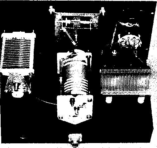 Figure 45 REAR VIEW OF TUNER SHOWING PLACEMENT OF MAJOR COMPONENTS. Rotary inductor Is driven by Johnson 176-208-4 counter dial. Coaxial input receptacle J1 is mounted directly below rotary inductor.  ohm termination. The transmitter is turned on (preferably at reduced input) and resonance is established in the amplifier tank circuit. The sensitivity control of the tuner is adjusted to provide near full scale deflection on the bridge meter. Various settings of SI, L2, and Cl should be tried to obtain a reduction of bridge reading. As tuner resonance is approached, the meter reading will decrease and the sensitivity control should be advanced. When the system is in resonance, the meter will read zero. All loading adjustments may then be made with the transpiitter controls. The tuner should be readjusted whenever the frequency of the transmitter is varied by an appreciable amount. Figure 46 CLOSE-UP OF SWR BRIDGE Simple SWR bridge Is mounted below the chassis of the tuner. Carbon resistors are mounted to fwo copper rings to form low inductance one-ohm resistor. Bridge capacitors form triangular configuration for lowest lead inductance. Balancing capacitor C2 is at lower right. High Frequency Antenna Arrays It is becoming of increasing importance in most types of radio communication to be capable of concentrating the radiated signal from the transmitter in a certain desired direction and to be able to discriminate at the receiver against reception from directions other than the desired one. Such capabilities involve the use of directive antenna arrays. Few simple antennas, except the single vertical element, radiate energy equally well in all azimuth (horizontal or compass) directions. All horizontal antennas, except those specifically designed to give an omnidirectional azimuth radiation pattern such as the turnstile, have some directive properties. These properties depend upon the length of the antenna in wavelengths, the height above ground, and the slope of the radiator. The various forms of the half-wave horizontal antenna produce maximum radiation at right angles to the wire, but the directional effect is not great. Nearby objects also minimize the directivity of a dipole radiator, so that it hardly seems worth while to go to the trouble to rotate a simple half-wave dipole in an attempt to improve transmission and reception in any direction. The half-wave doublet, folded dipole, zepp, single-wire-fed, matched impedance, and Johnson Q antennas all have practically the same radiation pattern when properly built and ad- justed They all are dipoles, and the feeder system, if it does not radiate in itself, will have no effect on the radiation pattern. 23-1 Directive Antennas When a multiplicity of radiating elements is located and phased so as to reinforce the radiation in certain desired directions and to neutralize radiation in other directions, a directive antenna array is formed. The function of a directive antenna when used for transmitting is to give an increase in signal strength in some direction at the expense of radiation in other directions. For reception, one might find useful an antenna giving little or no gain in the direction from which it is desired to receive signals if the antenna is able to discriminate against interfering signals and static arriving from other directions. A good directive transmitting antenna, however, can also be used to good advantage for reception. If radiation can be confined to a narrow beam, the signal intensity can be increased a great many times in the desired direction of transmission. This is equivalent to increasing the power output of the transmitter. On the higher frequencies, it is more economical to 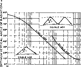 30 50 100 300 SOO 1000 3000 IOOOO GREAT CIRCLE DISTANCE IN MILES Figure 1 OPTIMUM ANGLE OF RADIATION WITH RESPECT TO DISTANCES Shown above is о plot of the optimum angle of radiation for one-hop and two-hop communication. An operating frequency close to the optimum working frequency for the communication distance is assumed. use a directive antenna than to increase transmitter power, if more than a few watts of power is being used. Directive antennas for the high-frequency range have been designed and used commercially with gains as high as 23 db over a simple dipole radiator. Gains as high as 35 db are common in direct-ray microwave communication and radar systems. Л gain of 23 db represents a power gain of 200 times and a gain of 35 db represents a power gain of almost 3500 times. However, an antenna with a gain of only 15 to 20 db is so sharp in its radiation pattern that it is usable to full advantage only for point-to-point work. The increase in radiated power in the desired direction is obtained at the expense of radiation in the undesired directions. Power gains of 3 to 12 db seem to be most practicable for amateur communication, since the width of a beam with this order of power gain is wide enough to sweep a fairly large area. Gains of 3 to 12 db represent effective transmitter power increases from 2 to 16 times. Horizontal Pattern Vertical Angle There is a certain optimum vertical angle of radiation for sky-wave communication, this angle being dependent upon distance, frequency, time of day, etc. Energy radiated at an angle much lower than this optimum angle is largely lost, while radiation at angles much  HAUF WAVE ANT--FXILL WAVE ANT. ......... 2 WAVES ANT. HORIZONTAL ANTENNAS IN FREE SPACE Figure 2 FREE-SPACE FIELD PATTERNS OF LONG-WIRE ANTENNAS The presence of the earth distorts the field pattern in such a manner that the azimuth pattern becomes о function of the elevation angle. higher than this optimum angle oftentimes is not nearly so effective. For this reason, the horizontal directivity pattern as measured on the ground is of no import when dealing with frequencies and distances dependent upon sky-wave propagation. It is the horizontal directivity (or gain or discrimination) measured at the most useful vertical angles of radiation that is of consequence. The horizontal radiation pattern; as measured on the ground, is considerably different from the pattern obtained at a vertical angle of 15°, and still more different from a pattern obtained at a vertical angle of 30°. In general, the energy which is radiated at angles higher than approximately 30° above the earth is effective at any frequency only for local work. For operation at frequencies in the vicinity of 14 Mc, the most effective angle of radiation is usually about 15° above the horizon, from any kind of antenna. The most effective angles for 10-meter operation are those in the vicinity of 10°. Figure 1 is a chart giving the optimum vertical angle of radiation for sky-wave propagation in terms of the great-circle distance between the transmitting and receiving antennas. 1 ... 42 43 44 45 46 47 48 ... 80 |
|
© 2026 AutoElektrix.ru
Частичное копирование материалов разрешено при условии активной ссылки |