 |
 |
 |
| Главная Журналы Популярное Audi - почему их так назвали? Как появилась марка Bmw? Откуда появился Lexus? Достижения и устремления Mercedes-Benz Первые модели Chevrolet Электромобиль Nissan Leaf |
Главная » Журналы » Simple coaxial reflectometer 1 ... 43 44 45 46 47 48 49 ... 80 HANDBOOK Long Wire Radiators 461 Figure 3 DIRECTIVE GAIN OF LONG-WIRE ANTENNAS О 12 10 Ы a. 4
i 23456769 DB POWER RATIO OF MAIN LOBE TO A DIPOLE Types of There is an enormous vari- Directive Arrays ety of directive antenna arrays that can give a substantial power gain in the desired direction of transmission or reception. However, some are more effective than others requiring the same space. In general it may be stated that long-wire antennas of various types, such as the single long wire, the V beam, and the rhombic, are less effective for a given space than arrays composed of resonant elements, but the long-wire arrays have the significant advantage that they may be used over a relatively large frequency range while resonant arrays are usable only over a quite narrow frequency band. 23-2 Long Wire Radiators Harmonically operated long wires radiate better in certain directions than others, but cannot be considered as having appreciable directivity unless several wavelengths long. The current in adjoining half-wave elements flows in opposite directions at any instant, and thus, the radiation from the various elements adds in certain directions and cancels in others. A half-wave doublet in free space has a doughnut of radiation surrounding it. A full wave has 2 lobes, 3 half waves 3, etc. When the radiator is made more than 4 half wavelengths long, the end lobes (cones of radiation) begin to show noticeable power gain over a half-wave doublet, while the broadside lobes get smaller and smaller in amplitude, even though numerous (figure 2). The horizontal radiation pattern of such antennas depends upon the vertical angle of radiation being considered. If the wire is more than 4 wavelengths long, the maximum radiation at vertical angles of 15 to 20° (useful for dx) is in line with the wire, being slightly greater a few degrees either side of the wire than directly off the ends. The directivity of the main lobes of radiation is not particularly sharp, and the minor lobes fill in between the main lobes to permit working stations in nearly all directions, though the power radiated broadside to the radiator will not be great if the radiator is more than a few wavelengths long. The directive gain of long-wire antennas, in terms of the wire length in wavelengths is given in figure 3- To maintain the out-of-phase condition in adjoining half-wave elements throughout the length of the radiator, it is necessary that a harmonic antenna be fed either at one end or at a current loop. If fed at a voltage loop, the adjacent sections will be fed in phase, and a different radiation pattern will result. The directivity of a long wire does not increase very much as the length is increased beyond about 15 wavelengths. This is due to the fact that all long-wire antennas are adversely affected by the r-f resistance of the wire, and because the current amplitude begins to become unequal at different current loops, as a result of attenuation along the wire caused by radiation and losses. As the length is increased, the tuning of the antenna becomes quite broad. In fact, a long wire about 15 waves long is practically aperiodic, and works almost equally well over a wide range of frequencies.
One of the most practical methods of feeding a long-wire antenna is to bring one end of it into the radio room for direct connection to a tuned antenna circuit which is link-coupled through a harmonic-attenuating filter to the transmitter. The antenna can be tuned effectively to resonance for operation on any harmonic by means of the tuned circuit which is connected to the end of the antenna. A ground is sometimes connected to the center of the tuned coil. If desired, the antenna can be opened and current-fed at a point of maximum current bf means of low-impedance ribbon line, or by a quarter-wave matching section and open line. 23-3 The V Anfenna If two long-wire antennas are built in the form of a V, it is possible to make two of the maximum lobes of one leg shoot in the same direction as two of die maximum lobes of the other leg of the V. The resulting antenna is bidirectional (two opposite directions) for the main lobes of radiation. Each side of the V can be made any odd or even number of quarter wavelengths, depending on the method of feeding the apex of the V. The complete system must be a multiple of half waves. If each leg is an even number of quarter waves long, the antenna must be voltage-fed at the apex; if an odd number of quarter waves long, current feed must be used. By choosing the proper apex angle, figure 4 and figure 5, the lobes of radiation from the two long-wire antennas aid each other to form a bidirectional beam. Each wire by itself would have a radiation pattern similar to that 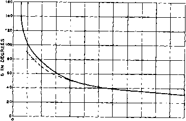 Figure 4 INCLUDED ANGLE FOR A V BEAM Showing the included angle between the legs af a V beam for various leg lengths. For optimum alignment of the radiation lobe at the correct vertical angle with leg lengths less than three wavelengths, the optimum Included angle Is shown by the doshed curve. 2 4 6 6 LENGTH IN L- WAVELENGTHS FEEDERS OH STUB 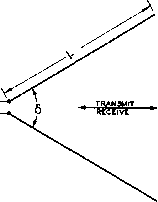 TYPICAL Figure 5 V BEAM ANTENNA for a long wire. The reaction of one upon the other removes two of the four main lobes, and increases the other two in such a way as to form two lobes of still greater magnitude. The correct wire lengths and the degree of the angle S are listed in the V-Antenna Design Table for various frequencies in the 10-, 20-and 40-meter amateur bands. Apex angles for all side lengths are given in figure 4. The gain of a V beam in terms of the side length when optimum apex angle is used is given in figure 6. The legs of a very long V antenna are usually so arranged that the included angle is twice the angle of the major lobe from a single wire if used alone. This arrangement concentrates the radiation of each wire along the bisector of the angle, and permits part of the other lobes to cancel each other. With legs shorter than 3 wavelengths, the best directivity and gain are obtained with a somewhat smaller angle than that determined by the lobes. Optimum directivity for a one-wave V is obtained when the angle is 90°
1 23<tSB7B9 10 LENGTH OF SIDE L Figure 6 DIRECTIVE GAIN OF A BEAM Tfc;s curve sbaws the approximate directive gain of a V beam with respect to a half-wave antenna located the same distance above ground, in terms af fhe side length L. rather than 180°, as determined by the ground pattern alone. If very long wires are used in the V, the angle between the wires is almost unchanged when the length of the wires in wavelengths is altered. However, an error of a few degrees causes a much larger loss in directivity aiid gain in the case of the longer V than in the shorter one. The vertical angle at which the wave is best transmitted or received from a horizontal V antenna depends largely upon the included angle. The sides of the V antenna should be at least a half wavelength above ground; commercial practice dictates a height of approximately a full wavelength above ground.
23-4 The Rhombic Antenna The terminated rhombic or diamond is probably the most effective directional antenna that is practical for amateur communication. This antenna is non-resonant, with the result that it can be used on three amateur bands, such as 10, 20, and 40 meters. When the antenna is non-resonant, i.e., properly terminated, the system is undirectional, and the wire dimensions are not critical. Rhombic When the free end is terminated Termination with a resistance of a value between 700 and 800 ohms the baclcwave is eliminated, the forward gain is increased, and the antenna can be used on several bands without changes. The terminating resistance should be capable of dissipating one-third the power output of the transmitter, and should have very little reactance. For medium or low power transmitters, the non-inductive plaque resistors will serve as a satisfactory termination. Several manufacturers offer special resistors suitable for terminating a rhombic anteima. The terminating device should, for technical reasons, present a small amount of inductive reactance at the point of termination. A compromise terminating device commonly used consists of a terminated 250-foot or longer length of line, made of resistance wire which does not have too much resistance per unit length. If the latter qualification is not met, the reactance of the line will be excessive. A 250-foot line consisting of no. 25 nichrome wire, spaced 6 inches and terminated with 800 ohms, will serve satisfactorily. Because of the attenuation of the line, the lumped resistance at the end of the line need dissipate but a few watts even when high power is used. A half-dozen 5000-ohm 2-watt carbon resistors in parallel will serve for all except very high power. The attenuating line may be folded back on itself to take up less room. The determination of the best value of terminating resistor may be made while receiving, if the input impedance of the receiver is approximately 800 ohms. The value of resistor which gives the best directivity on reception will not give the most gain when transmitting, but there will be little difference between the two conditions. The input resistance of the rhombic which is reflected into the transmission line that feeds it is always somewhat less than the terminating resistance, and is around 700 to 750 ohms when the terminating resistor is 800 ohms. 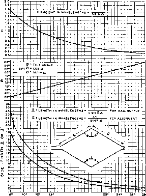 Ifl- ie 20 WAVE ANSLE Д Figure 7 RHOIMBIC ANTENNA DESIGN TABLE Design data is g/ven in terms of the wave angle (vertical angle of transmission and re-eepttan) of the antenna. The lengths I are for the maximum output design; the shorter lengths fare for the alignment method which gives approximately 1.5 db less gain with a considerable reduction In the space required for the arrtenna. The values of side length, tilt angle, and height for a given wave angle are obtained by drawing a vertical line upward from the desired wave angle. The antenna should be fed with a non-resonant line having a characteristic impedance of 650 to 700 ohms. The four corners of the rhombic should be at least one-half wavelength above ground for the lowest frequency of operation. For three-band operation the proper tilt angle ф for the center band should be observed. The rhombic antenna transmits a horizontally-polarized wave at a relatively low angle above the horizon. The angle of radiation (wave angle) decreases as the height above ground is increased in the same manner as with a dipole antenna. The rhombic should not be tilted in any plane. In other words, the poles should all be of the same height and the plane of the antenna should be parallel with the ground. HANDBOOK The Rhombic Antenna 465 Figure 8 TYPICAL RHOMBIC ANTENNA DESIGN The antenna system illustrated above may be used over the frequency range from 7 to 29 Mc. without change. The directivity of the system may be reversed by the system discussed In the text. 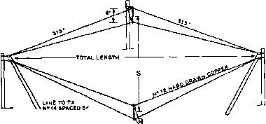 SPACINS BETWEEN SIDES S,> 214 FEET TOTAL LENCTH e 2 FEET H = 50 TERMINATING LINE OF 250 OF N- 26 NICHROME SPACED 6 AND eOO-OHM ie-WATT CARBON RESISTOR AT END. 6 2-WATT lOO-OHM RESISTORS IN SERIES A considerable amount of directivity is lost when the terminating resistor is left off the end and the system is operated as a resonant antenna. If it is desired to reverse the direction of the antenna it is much better practice to run transmission lines to both ends of the antenna, and then run the terminating line to the operating position. Then with the aid of two d-p-d-t switches it will be possible to connect either feeder to the antenna changeover switch and the other feeder to the terminating line, thus reversing the direction of the array and maintaining the same termination for either direction of operation. Figure 7 gives curves fot optimum-design rhombic antennas by both the maximum-output method and the alignment method. The alignment method is about 1.5 db down from the maximum output method but requires only about 0.74 as much leg length. The height and tilt angle is the same in either case. Figure 8 gives construction data for a recommended rhombic antenna for the 7.0 through 29.7 Mc. bands. This antenna will give about 11 db gain in the 14.0-Mc. band. The approximate gain of a rhombic antenna over a dipole, both above normal soil, is given in figure 9- 23-5 Stacked-Dipale Arrays The characteristics of a half-wave dipole already have been described. When another dipole is placed in the vicinity and excited either directly or parasitically, the resultant radiation pattern will depend upon the spacing and phase differential, as well as the relative magnitude of the currents. With spacings less than 0.65 wavelength, the radiation is mainly broadside to the two wires (bidirectional) when there is no phase difference, and through the wires (end fire) when the wires are 180° out of phase. With phase differences between 0° Figure 9 RHOMBIC ANTENNA GAIN Showing the theoretical gain of a rhombic antenna, in terms of the side length, over a half-wave antenna mounted at the same height above the same type of soil. a и < X UJ a z z
0 1 2 3 4 5 e 7 6 9 10 11 12 13 14 15 16 17 IB I 20 fl. = LENGTH OF EACH LEG OF RHOMBIC IN WAVELENGTH. ? PLANE OF WIRES END VIEW leO OUT OF PHASE (FLAT-TOP BEAM, ETC.) 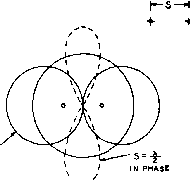 (LAZr H, STERBA CURTAIN) Figure 10 RADIATION PATTERNS OF A PAIR OF DIPOLES OPERATING WITH IN-PHASE EXCITATION, AND WITH EXCITATION 180 OUT OF PHASE If the dipoles are oriented horixontally most of the directivity will be In the vertical plane; if they are oriented vertically most of the directivity will be in the horizontal plane. and 180° (45°, 90°, and 135° for instance), the pattern is unsymmetrical, the radiation being greater in one direction than in the opposite direction. With spacings of more than 0.8 wavelength, more than two main lobes appear for all phasing combinations; hence, such spacings are seldom used. In-Phase With the dipoles driven so as to Spacing be in phase, the most effective spacing is between 0.5 and 0.7 wavelength. The latter provides greater gain, but minor lobes are present which do not appear at 0.5-wavelength spacing. The radiation is broadside to the plane of the wires, and the gain is slightly greater than can be obtained from two dipoles out of phase. The gain falls off rapidly for spacings less than 0.375 wavelength, and there is little point in using spacing of 0.25 wavelength or less with in-phase dipoles, except where it is desirable to increase the radiation resistance. (See Multi-Wire Doublet.) Out of Phase When the dipoles are fed 180° Spacing out of phase, the directivity is through the plane of the wires, and is greatest with close spacing, though there is but little difference in the pattern after the spacing is made less than 0.125 wavelength. The radiation resistance becomes so low for spacings of less than 0.1 wavelength that such spacings are not practicable. 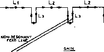 QUARTER-WAVE STUBS APPROX. 4.5 DB Figure 11 THE FRANKLIN OR COLINEAR ANTENNA ARRAY An antenna of this type, regardless of the number af elements, attains all of its directivity through sharpening of the horizontal or azimuth radiation pattern; no vertical directivity Is provided. Hence a long antenna af this type has an extremely sharp azimuth pattern, but no vertical directivity. In the three foregoing examples, most of the directivity provided is in a plane at a right angle to the wires, though when out of phase, the directivity is in a line through the wires, and when in phase, the directivity is broadside to them. Thus, if the wires are oriented vertically, mostly horizontal directivity will be provided. If the wires are oriented horizontally, most of the directivity obtained will be vertical directivity. To increase the sharpness of the directivity in all planes that include one of the wires, additional identical elements are added in the line of the wires, and fed so as to be in phase. The familiar H array is one array utilizing both types of directivity in the manner prescribed. The two-section Kraus flat-top beam is another. These two antennas in their various forms are directional in a horizontal plane, in addition to being low-angle radiators, and are perhaps the most practicable of the bidirectional stacked-dipole arrays for amateur use. More phased elements can be used to provide greater directivity in planes including one of the radiating elements. The H then becomes a Sterba-curtain array. For unidirectional work the most practicable stacked-dipole arrays for amateur-band use are parasitically-excited systems using relatively close spacing between the reflectors and the directors. Antennas of this type are described in detail in a later chapter. The next most practicable unidirectional array is an H or a Sterba curtain with a similar system placed approximately one-quarter wave behind. The use of a reflector system in conjunction with any type of stacked-dipole broadside array will increase the gain by 3 db. COLINEAR ANTENNA DESIGN CHART
А В А-В=150л feed point Ml N APPROX. 3DB Figure 12 DOUBLE EXTENDED ZEPP ANTENNA For host rosults, antonna shouN be tuned to operating frequency by means af grld-dlp ascillator. Colinear The simple colinear antenna array Arrays is a very effective radiating system for the 3.5-Mc. and 7.0-Mc. bands, but its use is not recommended on higher frequencies since such arrays do not possess any vertical directivity. The elevation radiation pattern for such an array is essentially the same as for a half-wave dipole. This consideration applies whether the elements are of normal length or are extended. The colinear antenna consists of two ot more radiating sections from 0.5 to 0.65 wavelengths long, with the current in phase in each section. The necessary phase reversal between sections is obtained through the use of resonant tuning stubs as illustrated in figure 11. The gain of a colinear array using half-wave elements (in decibels) is approximately equal to the number of elements in the array. The exact figures are as follows: Number of Elements 2 3 4 5 6 Gain in Decibels 1.8 3.3 4.5 5-3 6.2 As additional in-phase colinear elements are added to a doublet, the radiation resistance goes up much faster than when additional half waves are added out of phase (harmonic operated antenna). For a colinear array of from 2 to 6 elements, -72л. balanced lines -of equal length oft phase- transmitter phase-reversing switch FOR cloverleaf pattern Figure 13 TWO COLINEAR HALF-WAVE ANTENNAS IN PHASE PRODUCE A 3 DB GAIN WHEN SEPARATED ONE-HALF WAVELENGTH the terminal radiation resistance in ohms at any current loop is approximately 100 times the number of elements. It should be borne in mind that the gain from a colinear antenna depends upon the sharpness of the horizontal directivity since no vertical directivity is provided. An array with several colinear elements will give considerable gain, but will have a sharp horizontal tadiation pattern. Double Extended The gain of a conventional Zepp two-element Franklin colin- ear antenna can be increased to a value approaching that obtained from a three-element Franklin, simply by making the two radiating elements 230° long instead of 180° long. The phasing stub is shortened correspondingly to maintain the whole array in resonance. Thus, instead of having 0.5-wave-length elements and 0.25-wavelength stub, the elements are made 0.64 wavelength long and the stub is approximately 0.11 wavelength long. Dimensions for the double extended Zepp are given in figure 12. The vertical directivity of a colinear antenna having 230° elements is the same as for one having 180° elements. There is little advantage in using extended sections when the total length of the array is to be greater than about 1.5 wavelength overall since the gain -ess- Id- eas--
Figure 14 PRE-CUT LINEAR ARRAY FOR 40-METER OPERATION of a colinear antenna is proportional to the overall length, whether the individual radiaring elements are M wave, Vi wave or % wave in length. Spaced Half The gain of two colinear half Wove Antennas waves may be increased by increasing the physical spacing between the elements, up to a maximum of about one half wavelength. If the half wave elements are fed with equal lengths of transmission line, poled correctly, a gain of about 3.3 db is produced. Such an antenna is shown in figure 13. By means of a phase reversing switch, the two elements may be operated out of phase, producing a cloverleaf pattern with slightly less maximum gain. A three element precut array for 40 meter operation is shown in figure 14. It is fed directly with 300 ohm ribbon line, and may be matched to a 52 ohm coaxial ouфut transmitter by means of a Balun, such as the Barker & Williamson 3975. The antenna has a gain of about 3.2 db, and a beam width at half-power points of 40 degrees. 23-6 Broadside Arrays Colinear elements may be stacked above or below another string of colinear elements to produce what is commonly called a broadside array. Such an array, when horizontal elements are used, possesses vertical directivity in proportion to the number of broadsided (vertically stacked) sections which have been used. Since broadside arrays do have good vertical directivity their use is recommended on the 14-Mc. band and on those higher in frequency. One of the most popular of simple broadside arrays is the Lazy H array of figure 15. Horizontal colinear elements stacked two above two make up this antenna system which is highly recommended for work on frequencies above perhaps 14-Mc. when moderate gain without too much directivity is desired. It has high radiation resistance and a gain of approximately 5.5 db. The high radiation resistance results in low voltages and a broad resonance curve, which permits use of inexpensive insulators and enables the array to be used over a fairly wide range in frequency. For dimensions, see the stacked dipole design table. Stacked Vertical stacking may be applied Dipoles to strings of colinear elements longer than two half waves. In such arrays, the end quarter wave of each string of radiators usually is bent in to meet NON-RESOMANT FEED  QUARTER-WAVE STUB SAIN APPROX. S.5 DS 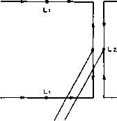 RESONANT FEED LINE Figure 15 THE LAZY H ANTENNA SYSTEM Stacking the coffnear pairs gives both horizontal and vertical directivity. As shown, the array will give about 5.5 db gain. Note that the array may be fed either at the center of the phasing section or at the bottom; if fed at the bottom the phasing section mOst be twisted through 780 . a similar bent quarter wave from the opposite end radiator. This provides better balance and better coupling between the upper and lower elements when the array is current-fed. Arrays of this type are shown in figure 16, and are commonly known as curtain arrays. Correct length for the elements and stubs can be determined for any stacked dipole array from the Stacked-Dipole Design Table. In the sketches of figure 16 the arrowheads represent the direction of current flow at any given instant. The dots on the radiators repre- 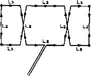 ЭОО-ОНМ TWINLEAD 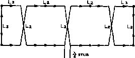 GAIN APPROX. 6 DB NON-RESONANT FEEDER GAIN APPROX. a DB l2 iLz Lzl La ЭОО-ОНМ TWINLEAD . GAIN APPROX. 6 DB Figure 16 THE STERBA CURTAIN ARRAY Approximofe directive goins along with aher-ntitivB feed methods ore shown. sent points of maximum current. All arrows ould point in the same direction in each portion of the radiating sections of an antenna in order to provide a field in phase for broadside radiation. This condition is satisfied for the arrays illustrated in figure 16. Figures 16A and 16C show simple methods of feeding a short Sterba curtain, while an alternative method of feed is shown in the higher gain antenna of figure 16B. In the case of each of the arrays of figure 16, and also the *Lazy H of figure 15, the array may be made unidirectional and the gain increased by 3 db if an exactly similar array is constructed and placed approximately }4 wave behind the driven array. A screen or mesh of wires slightly greater in area than the antenna array may be used instead of an additional array as a reflector to obtain a unidirectional system. The spacing between the reflecting wires may vary from 0.05 to 0.1 wavelength with the spacing between the reflecting wires the smallest directly behind the driven elements. The wires in the untuned reflecting system should be parallel to the radiating elements of the array, and the spacing of the complete reflector system should be approximately 0.2 to 0.25 wavelength behind the driven elements. On frequencies below perhaps 100 Mc it normally will be impracticable to use a wire-screen reflector behind an antenna array such as a Sterba curtain or a Lazy H. Parasitic elements may be used as reflectors or directors, but parasitic elements have the disadvantage that their operation is selective with respect to relatively small changes in frequency. Nevertheless, parasitic reflectors for such arrays are quite widely used. The X-Arroy In section 23-5 it was shown how two dipoles may be arranged in phase to provide a power gain of (some) 3 db. If two such pairs of dipoles are stacked
L- 1--L- h-L □ с 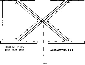
75aTRAN5MIS3ION LINE Figure 17 THE X-ARRAY FOR 28 MC, 21 MC, OR 14 MC The entire array (with the exception of the 75-obm feed line) Is constructed of 300-ohm ribbon line. Be sure phasing lines (P) are poled correctly, as shown. in a vertical plane and properly phased, a simplified form of in-phase curtain is formed, providing an overall gain of about 6 db. Such an array is shown in figure 17. In this X-array, the four dipoles are all in phase, and are fed by four sections of 300-ohm line, each one-half wavelength long, the free ends of all four lines being connected in parallel. The feed impedance at the junction of these four lines is about 75 ohms, and a length of 75-ohm Twin-Lead may be used for the feedline to the array. An array of this type is quite small for the 28-Mc. band, and is not out of the question for the 21-Mc. band. For best results, the bottom section of the array should be one-half wavelength above ground. The Double-Bruce Array The Bruce Beam consists of a long wire folded so that vertical elements carry in-phase currents while the horizontal elements carry out of phase currents. Radiation from the horizontal sections is low since only a small current flows in this part of the wire, and it is largely phased-out. Since the height of the Bruce Beam is only one-quarter wavelength, the gain per linear foot of array is quite low. Two Bruce Beams may be combined as shown in figure 18 to produce the Double Bruce array. A four section Double Bruce will give a vertically polarized emission, with a power gain of 5 db over a simple 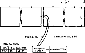 Figure 18 THE DOUBLE-BRUCE ARRAY FOR 10, 15, AND 20 METERS If a 600-obm feed line Is used, the 20-meter array will also perform on 10 meters as a Sterba curtain, with an approximate gain of 9 db. dipole, and is a very simple beam to construct. This antenna, like other so-called broadside arrays, radiates maximum power at right angles to the plane of the array. The feed impedance of the Double Bruce is about 750 ohms. The array may be fed with a one-quarter wave stub made of 300-ohm ribbon line and a feedline made of 150-ohm ribbon line. Alternatively, the array may be fed directly with a wide-spaced 600-ohm transmission line (figure 18). The feedline should be brought away from the Double Bruce for a short distance before it drops downward, to prevent interaction between the feedline and the lower part of the center phasing section of the array. For best results, the bottom sections of the array should be one-half wavelength above ground. Arrays such as the X-array and the Double Bruce are essentially high impedance devices, and exhibit relatively broad-band characteristics. They are less critical of adjustment than a parasitic array, and they work well over a wide frequency range such as is encountered on the 28-29.7 Mc. band. The Bi-Square* Broadside Array Illustrated in figure 19 is a simple method of feeding a small broadside array first described by W6BCX several years ago as a practical method of suspending an effective array from a single pole. As two arrays of this type can be supported at right angles from a single pole without interaction, it offers a solution to the problem of suspending two arrays in a restricted space with a minimum of erection work. The free space directivity gain is slightly less than that of a Lazy H, but is 1 ... 43 44 45 46 47 48 49 ... 80 |
||||||||||||||||||||||||||||||||||||||||||||||||||||||||||||||||||||||||||||||||||||||||||||||||||||||||||||||||||||||||||||||||||||||||||||||||||||||||||||||||||||||||||||||||||||||||||||||||||||||||||||||||||||||||||||||||||||||||||||||||||||||||||||||||||||||||||||||||||||||||||||||||||||||||||||||||||||||||||||||||||||||||||||||||||||||||||||||||||||||||||||||||||||||||||||||||||||||||||||||||||||||||||||||||||||||||||||||||||||||||||||||||||||||||||||||||||||||||||||||||||||||||||||||||||||||||||||||||||||||||||||||||||||||||||||||||||||||||||||||||||||||||||||||||||||||||||||||||||||||||||||||||||||||||||||||||||||||||||||||||||||||||||||||||||||||||||||||||||||||||||||||||||||||||||||||||||||||||||||||||||||||||||||||||||||||||||||||||||||||||||||||||||||||||||||||||||||||||||||||||||||||||||||||||||||||||||||||||||||||||||||||||||||||||||||||||||||||||||||||||||||||||||||||||||||||||||||||||||||||||||||||||||||||||||||||||||||||||||||||||||||||||||||||||||||||||||||||||||||||
|
© 2026 AutoElektrix.ru
Частичное копирование материалов разрешено при условии активной ссылки |