 |
 |
 |
| Главная Журналы Популярное Audi - почему их так назвали? Как появилась марка Bmw? Откуда появился Lexus? Достижения и устремления Mercedes-Benz Первые модели Chevrolet Электромобиль Nissan Leaf |
Главная » Журналы » Simple coaxial reflectometer 1 ... 44 45 46 47 48 49 50 ... 80 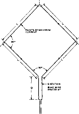 DIMENSIONS lOM. I5M. гом
GAIN APPROX. 4DB -1 iOA LINE to TRANSMITTER Figure 19 THE BI-SQUARE BROADSIDE ARRAY This bidirectional array is related to the Lazy H, and in spite af the oblique elements, is horizontally polarized. It has slightly less gain and directivity than the Lazy H, the free space directivity gain being approximately 4 db. Its chief advantage is the fact that only a single pole Is required for support, and two such arrays may be supported from a single pole without interaction if the planes of the elements are at right angles. A 600-ohm line may be substituted for the Twin-Lead, and either operated as a resonant line, or made гюп-resonant by fhe incorporation of a matching stub. still worthwhile, being approximately 4 db over a half-wave horizontal dipole at the same average elevation, When two Bi-Square arrays are suspended at right angles to each other (for general coverage) from a single pole, the Q sections should be well separated or else symmetrically arranged in the form of a square (the diagonal conductors forming one Q section) in order to minimize coupling between them. The same applies to the line if open construction is used instead of Twin-Lead, but if Twin-Lead is used the coupling can be made negligible simply by separating the two Twin-Lead lines by at least two inches and twisting one Twin-Lead so as to effect a transposition every foot or so. 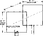 С = 50 JUJUf tunb for minimum pickup off rear of be a m. STUB = 10 1Г14 E, SPACED 3 RADIATOR 150 OHM BALAMCED LINE TO TLJNIM5 UNIT OR TRANSMITTER. NOTE; side lenhth- iva for zi mc. itt for ы mc. element spacins 9в-for each band. stub length approx. is for Zt mc. го- for 14 mc. Figure 20 THE CUBICAL-QUAD ANTENNA FOR THE lO-METER BAND When tuned feeders are employed, the Bi-Square array can be used on half frequency as an end-fire vertically polarized array, giving a slight practical dx signal gain over a vertical half-wave dipole at the same height. A second Bi-Square serving as a reflector may be placed 0.15 wavelength behind this antenna to provide an overall gain of 8.5 db. The reflector may be tuned by means of a quarter-wave stub which has a moveable shorting bar at the bottom end. The stub is used as a substitute for the Q-section, since the reflector employs no feed line. The Cubical- A smaller version of the Bi-Quad Antenna Square antenna is the Cubical-Quad antenna. Two half-waves of wire are folded into a square that is one-quarter wavelength on a side, as shown in figure 20. The array radiates a horizontally polarized signal. A reflector placed 0.15 wavelength behind the antenna provides an overall gain of some 6 db. A shorted stub with a paralleled tuning capacitor is used to resonate the reflector. The Cubical-Quad is fed with a 150-ohm line, and should employ some sort of antenna tuner at the transmitter end of the line if a pi-network type transmitter is used. There is a small standing wave on the line, and an open -3 = 4- DIMENSIONS lOM. ISM. 20M. -Э00ЛХ1ВВ0Ы LINE GAIN APPROX. 7.5 DB Figure 21 THE SIX-SHOOTER BROADSIDE ARRAY wire line should be employed if the antenna is used with a high power transmitter. To tune the reflector, the back of the antenna is aimed at a nearby field-strength meter and the reflector stub capacitor is adjusted for minimum received signal at the operating frequency. This antenna provides high gain for its small size, and is recommended for 28-Mc. work. The elements may be made of number 14 enamel wire, and the array may be buUt on a light bamboo or wood framework. The Six-Shooter As a good compromise be-Broadside Arroy tween gain, directivity, compactness, mechanical simplicity, ease of adjustment, and band width the array of figure 21 is recommended for the 10 to 30 Mc range when rhe additional array width and greater directivity are not obtainable. The free space directivity gain is approximately 7.5 db over one element, and the pracrical dx signal gain over one element at the same average elevarion is of abour the same magnitude when the array is sufficiently elevated. To show up to best advantage the array should be elevated sufficiently to put the lower elements well in the clear, and preferably at least 0.5 wavelength above ground. The Bobtoil Bidirectional Broadside Curtain Another application of vertical orientation of the radiating elements of an array in order to obtain low-angle radiation at the lower end of the h-f range with low pole heights is illustrated in figure 22. When precut to the specified dimensions this single pattern array will perform well over the 7-Mc. amateur band or the 4-Mc. amateur phone band. For the 4-Mc. band the required two poles need be only 70 feet high, and the array will provide a practical signal 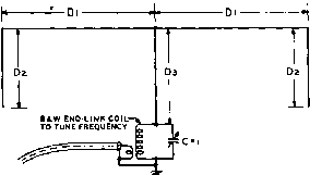 52 a COAXIAL LINE 00 JUJUF DIMENSIONS 40 M. SO M.
Figure 22 BOBTAIL BIDIRECTIONAL BROADSIDE CURTAIN FOR THE 7-MC. OR THE 4.0.MC. AMATEUR BANDS This simple vertically polarized array provides low angle radiation and response with comparatively low pale heights, and is very effective for dx work on the 7-Mc. band ar the 4.0-Mc. phone band. Because of the phase relationships, radiation from the horizontal portion of the antenna is effectively suppressed. Very little current flows in the ground lead to the coupling tank; so an elaborate ground system is not required, and the length of the ground lead is not critical so long as it uses heavy wire and is reoson-ably short. gain averaging from 7 ro 10 db over a horizontal half-wave dipole utilizing the same pole height when the path length exceeds 2500 miles. The horizontal directivity is only moderate, the beam width at the half power points being slightly greater than that obtained from three cophased vertical radiators fed with equal currents. This is explained by the fact that the current in each of the two outer radiators of this array carries only about half as much current as the center, driven element. While this binomial current distribution suppresses the end-fire lobe that occurs when an odd number of parallel radiators with half-wave spacing are fed equal currents, the array still exhibits some high-angle radiation and response off the ends as a result of imperfect cancellation in the flat top portion. This is not sufficient to affect the power gain appreciably, but does degrade the discrimination somewhat. A moderate amount of sag can be tolerated at the center of the flat top, where it connects to the driven vertical element. The poles and antenna tank should be so located with respect to each other that the driven vertical element drops approximarely straighr down from the flat top. Normally the antenna tank will be located in the same room as the transmitter, to facilitate adjustment when changing frequency. In this case it is recommended that the link coupled tank be located across the room from the transmitter if much power is used, in order to minimize t-f feedback difficulties which might occur as a result of the asymmetrical high impedance feed. If tuning of the antenna tank from the transmitter position is desired, flexible shafting can be run from the antenna tank condenser to a control knob at the transmitter. The lower end of the driven element is quite hot if much power is used, and the lead-in insulator should be chosen with this in mind. The ground connection need not have very low resistance, as the current flowing in the ground connection is comparatively small. A stake or pipe driven a few feet in the ground will suffice. However, the ground lead should be of heavy wire and preferably the length should not exceed about 10 feet at 7 Mc. or about 20 feet at 4 Mc. in order to minimize reactive effects due to its inductance. If it is impossible to obtain this short a ground lead, a piece of screen or metal sheet about four feet square may be placed parallel to the earth in a convenient location and used as an artificial ground. A fairly high C/L ratio ordinarily will be required in the antenna tank in order to obtain adequate coupling and loading. 23-7 End-Fire DIrecfivity By spacing two half-wave dipoles, or colinear arrays, at a distance of from 0.1 to 0.25 wavelength and driving the two 180° out of phase, directivity is obtained through the two wires at tight angles to them- Hence, this type of bidirectional array is called end fire. A better idea of end-fire directivity can be obtained by referring to figure 10. Remember that end-fire refers to the radiation with respect to the two wires in the array rather than with respect to the array as a whole. The vertical directivity of an end-fire bidirectional array which is oriented horizontally can be increased by placing a similar end-fire array a half wave below it, and excited in the same phase. Such an array is a combination broadside and end-fire affair. Kraus Flat-Tap A very effective bidirectional Beam end-fire array is the Kraus or 8JK Flat-Top Beam. Essentially, this antenna consists of two close-spaced dipoles or colinear arrays. Because of the close spacing, it is possible to obtain the proper phase relationships in multi-section flat tops by crossing the wires at the voltage loops, rather than by resorting to phasing stubs. This greatly simplifies the array. (See figure 23.) Any number of sections may be used, though the one- and two-section arrangements are the most popular. Little extta gain is obtained by using more than four sections, and trouble from phase shift may appear. A center-fed single-section flat-top beam cut according to the table, can be used quite successfully on its second harmonic, the pattern being similar except that it is a little sharper. The single-section anray can also be used on its fourth harmonic with some success, though there then will be four cloverleaf lobes, much the same as with a full-wave antenna. If a flat-top beam is to be used on more than one band, tuned feeders are necessary. The radiation resistance of a flat-top beam is rather low, especially when only one section is used. This means that the voltage will be high at the voltage loops. For this reason, especially good insulators should be used for best results in wet weather. The exact lengths for the radiating elements are not especially critical, because slight deviations from the correct lengths can be compensated in the stub or tuned feeders. Proper stub adjustment is covered in Chapter Twenty-five. Suitable radiator lengths and approximate stub dimensions are given in the accompanying design table. Figure 23 shows top views of eight types of flat-top beam antennas. The dimensions for using these antennas on different bands are given in the design table. The 7- and 28-Mc. bands are divided into two parts, but the dimensions for either the low- or high-frequency ends of these bands will be satisfactory for use over the entire band. In any case, the antennas are tuned to the frequency used, by adjusting the shorting wire on the stub, or tuning the feeders, if no stub is used. The data in the table may be extended to other bands or frequencies by applying the proper factor. Thus, for 50 to 52 Mc. operation, the values for 28 to 29 Mc. are divided by 1.8. All of the antennas have a bidirectional horizontal pattern on their fundamental frequency. The maximum signal is broadside to the flat top. The single-section type has this pattern on both its fundamental frequency and second harmonic. The other types have four main lobes of radiation on the second and higher harmonics. The nominal gains of the different types over a half-wave comparison antenna are as follows: single-section, 4 db; two-section, 6 db; four-section, 8 db. The maximum spacings given make the beams less critical in their adjustments. Up 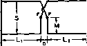 k-i-3-4u- CENTEft FED TO CENTER OF FLAT TOP END FED 1 -SECTION MATCHING STUB I-SECTION 2-SECTlON STUB OF FEEDERS CONNECT AT F F 3-SECTION 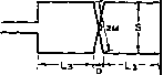 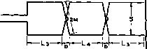 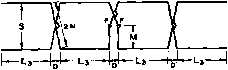 4-SECTlON 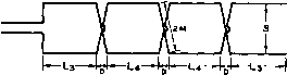 FIGURE 23 FLAT-TOP BEAM (8JK ARRAY) DESIGN DATA.
Dimension chart for flat-lop beam antennas. The meanings of the symbols are as follows: Ll, Ll L, and L the lengths of the sides of the flat-lop sections as shown. Li is length of the sides of single-section center-fed, Lt single-section enJ-fed and 2.iect$on center-fed. La 4-section center-fed and end-sections of 4-section end-fed, and L, middle sections of 4-section end-fed. S, the spacing between the flat-lop wires. M, the wire length from the outside to the center of each cross-over. D, the spacing lengthwise between sections. A (Va), the approximate length for a quarter-ware stub. A (V2), the approximate length for a half-ware stub, A (Vi), the approximate length for a three-quarter ware stub. X, the approximate distance above the shorting wire of the stub for the connection of a 600-ohm line. This distance, as given in the table, is approximately correct only for 2-section flat-taps. For single-section types il will be smaller and for 3- and 4-seclion types il will be larger. The lengths given for a half-wave stub are applicable only to single-section center-fed flat-tops. To be certain of sufficient stub length, it is advisable to make the stub a foot or so longer than shown in the table, especially with the end-fed types. The lengths. A, are measured from the point where the stub connects to the fiat-top. Both the center and end-fed types may be used horiontidly. However, where a vertical antenna is desired, the flat-tops can be turned on end. In this case, the end-fed types may be more convenient, feeding from the lower end. HANDBOOK Triplex Beam 475 Figure 24 THE TRIPLEX FLAT-TOP BEAM ANTENNA FOR 10, 15 AND 20 METERS 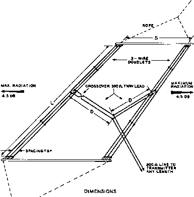 У
to one-quarter wave spacing may be used on the fundamental for the one-section types and also the two-section center-fed, but it is not desirable to use more than 0.15 wavelength spacing for the other types. Although the center-fed type of flat-top generally is to be preferred because of its symmetry, the end-fed type often is convenient or desirable. For example, when a flat-top beam is used vertically, feeding from the lower end is in most cases more convenient. If a multisection flat-top array is end-fed instead of center-fed, and tuned feeders are used, stations off the ends of the array can be worked by tying the feeders together and working the whole affair, feeders and all, as a long-wire harmonic antenna. A single-pole double-throw switch can be used for changing the feeders and directivity. The Triplex The Triplex beam is a modified Beam version of the W8JK antenna which uses folded dipoles for the half wave elements of the array. The use of folded dipoles results in higher radiation resistance of the array, and a high overall system performance. Three wire dipoles are used for the elements, and 300-ohm Twin-Lead is used for the two phasing sections. A recommended assembly for Triplex beams for 28 Mc, 21 Mc, and 14 Mc. is shown in figure 24. The gain of a Triplex beam is about 4.5 db over a dipole. 23-8 Combination End-Fire anti Broadside Arrays Any of the end-fire arrays previously described may be stacked one above the other or placed end to end (side bv side) to give greater directivity gain while maintaining a bidirectional characteristic. However, it must be kept in mind that to realize a worthwhile increase in directivity and gain while maintaining a bidirectional pattern the individual arrays must be spaced sufficiently to reduce the mutual impedances to a negligible value. When two flat top beams, for instance, are placed one above the other or end to end, a center spacing on the order of one wavelength is required in order to achieve a worthwhile increase in gain, or approximately 3 db. Thus it is seen that, while maximum gain occurs with two stacked dipoles at a spacing of about 0.7 wavelength and the space directivity gain is approximately 5 db over one element under these conditions; the case of two flat top or parasitic arrays stacked one above the other is another story. Maximum gain will occur at a greater spacing, and the gain over one array will not appreciably exceed 3 db. When two broadside curtains are placed one ahead of the other in end-fire relationship, the aggregate mutual impedance between the two curtains is such that considerable spacing is required in order to realize a gain approaching 3 db (the required spacing being a function of the size of the curtains). While it is true that a space directivity gain of approximately 4 db can be obtained by placing one, half-wave dipole an eighth wavelength ahead of another and feeding them 180 degrees out of phase, a gain of less than 1 db is obtained when the same procedure is applied to two large broadside curtains. To obtain a gain of approximately 3 db and retain a bidirectional pattern, a spacing of many wavelengths is required between two large curtains placed one ahead of the other. A different situation exists, however, when one driven curtain is placed ahead of an identical one and the two are phased so as to give a unidirectional pattern. When a unidirectional pattern is obtained, the gain over one curtain will be approximately 3 db regardless of the spacing. For instance, two large curtains placed one a quarter wavelength ahead of the other may have a space directivity gain of only 0.5 db over one curtain when the two are driven 180 degrees out of phase to give a bidirectional pattern (the type of pattern obtained with a single curtain). However, if they are driven in phase quadrature (and with equal currents) the gain is approximately 3 db. The directivity gain of a composite array also can be explained upon the basis of the directivity patterns of the component arrays alone, but it entails a rather complicated picture. It is sufficient for the рифове of this discussion to generalize and simplify by saying that the greater the directivity of an end-fire array, the farther an identical array must be spaced from it in broadside relationship to obtain optimum performance; and the greater the directivity of a broadside array, the farther an identical array must be spaced from it in end-fire relationship to obtain optimum performance and retain the bidirectional characteristic. It is important to note that while a bidirectional end-fire pattern is obtained with two driven dipoles when spaced anything under a half wavelength, and while the proper phase relationship is 180 degrees regardless of the spacing for all spacings not exceeding one half wavelength, the situation is different in the case of two curtains placed in end-fire relationship to give a bidirectional pattern. For maximum gain at zero wave angle, the curtains should be spaced an odd multiple of one half wavelength and driven so as to be 180 degrees out of phase, or spaced an even multiple of one half wavelength and driven in the same phase. The optimum spacing and phase relationship will depend upon the directivity pattern of the individual curtains used alone, and as previously noted the optimum spacing increases with the size and directivity of the component arrays. A concrete example of a combination broadside and end-fire array is two Lazy H arrays spaced along the direction of maximum radiation by a distance of four wavelengths and fed in phase. The space directivity gain of such an arrangement is slightly less than 9 db. However, approximately the same gain can be obtained by juxtaposing the two arrays side by side or one over the other in the same plane, so that the two combine to produce, in effect, one broadside curtain of twice the area. It is obvious that in most cases it will be more expedient to increase the area of a broadside array than to resort to a combination of end-fire and broadside directivity. One exception, of course, is where two curtains are fed in phase quadratxire to obtain a unidirectional pattern and space directivity gain of approximately 3 db with a spacing between curtains as small as one quarter wavelength. Another exception is where very low angle radiation is desired and the maximum pole height is strictly limited. The two aforementioned Lazy H arrays when placed in end-fire relationship will have a considerably lower radiation angle than when placed side by side if the array elevation is low, and therefore may under some conditions exhibit appreciably more practical signal gain. Y-H-F and U-H-F Antennas The very-high-frequency or vh-f frequency range is defined as that range falling between 30 and 300 Mc. The ultra-high-frequency or u-b-f range is defined as falling between ЗОО and 3000 Mc. This chapter will be devoted to the design and construction of antenna systems for operation on the amateur 50-Mc., 144-Mc., 235-Mc., and 420-Mc. bands. Although the basic principles of anteima operation are the same for all frequencies, the shorter physical length of a wave in this frequency range and the differing modes of signal propagation make it possible and expedient to use antenna systems different in design from those used on the range from 3 to 30 Mc. 24-1 Antenna Requirements Any type of antenna system useable on the lower frequencies may be used in the v-h-f and u-h-f bands. In fact, simple non-directive half-wave or quarter-wave vertical antennas are very popular for general transmission and reception from all directions, especially for short-range work. But for serious v-h-f or u-h-f work the use of some sort of directional antenna array is a necessity. In the first place, when the transmitter power is concentrated into a narrow beam the apparent transmitter power at the receiving station is increased many times. A billboard array or a Sterba curtain having a gain of 16 db will make a 25-watt transmitter sound like a kilowatt at the other station. Even a much simpler and smaller three-or four-element parasitic array having a gain of 7 to 10 db will produce a marked improvement in the received signal at the other station. However, as all v-h-f and u-h-f workers know, the most important contribution of a high-gain antenna array is in reception. If a remote station cannot be heard it obviously is impossible to make contact. The limiting factor in v-h-f and u-h-f reception is in almost every case the noise generated within the receiver itself. Atmospheric noise is almost nonexistent and ignition interference can almost invariably be reduced to a satisfactory level through the use of an effective noise limiter. Even with a grounded-grid or neutralized triode first stage in the receiver the noise contribution of the first tuned circuit in the receiver will be relatively large. Hence it is desirable to use an antenna system which will deliver the greatest signal voltage to the first tuned circuit for a given field strength at the receiving location. Since the field intensity being produced at the receiving location by a remote transmitting station may be assumed to be constant, the receiving antenna which intercepts the greatest amount of wave front, assuming that the polarization and directivity of the receiving antenna is proper, will be the antenna which gives the best received signal-to-noise ratio. An antenna which has two square wavelengths effective area will piclc up twice as much signal power as one which has one square wavelength area, assuming the same general type of antenna and that both are directed at the station being received. Many instances have been reported where a frequency band sounded completely dead with a simple dipole receiving antenna but when the receiver was switched to a three-element or larger array a considerable amounr of activity from 80 to 160 miles distant was heard. Angle of The useful portion of the signal Radiation in the v-h-f and u-h-f range for short or medium distance communication is that which is radiated at a very low angle with respect to the surface of die earth; essentially it is that signal which is radiated parallel to the surface of the earth. A vertical antenna transmits a portion of its radiation at a very low angle and is effective for this reason; its radiation is not necessarily effective simply because it is vertically polarized. A simple horizontal dipole radiates very little low-angle energy and hence is not a satisfactory v-h-f or u-h-f radiator. Directive arrays which concentrate a major portion of the radiated signal at a low radiation angle will prove to be effective radiators whether their signal is horizontally or vertically polarized. In all cases, the radiating system for v-h-f and u-h-f work should be as high and in the clear as possible. Increasing the height of the antenna system will produce a very marked improvement in the number and strength of the signals heard, regardless of the actual type of antenna used. Transmission Transmission lines to v-h-f and Lines u-h-f antenna systems may be either of the parallel-conductor or coaxial conductor type. Coaxial line is recommended for short runs and closely spaced open-wire line for longer runs. Wave guides may be used under certain conditions for frequencies greater than perhs 1500 Mc. but their dimensions become excessively great for frequencies much below this value. Non-resonant transmission lines will be found to be considerably more efficient on these frequencies than those of the resonant type. It is wise to to use the very minimum length of transmission line possible since transmission line losses at frequencies above about 100 Mc mount very rapidly. Open lines should preferably be spaced closer than is common for longer wavelengths, as 6 inches is an preciable fraction of a wavelength at 2 meters. Radiation from the line will be greatly reduced if 1-inch or 1У2-inch spacing is used, rather than the more common 6-inch spacing. Ordinary TV-type 300-ohm ribbon may be used on the 2-meter band for feeder lengths of about 50 feet or less. For longer runs, either the u-h-f or v-h-f TV open-wire lines may be used with good overall efficiency. The v-h-f line is satisfactory for use on the amateur 420-Mc. band. Antenna It is recommended that the same Changeover antenna be used for transmitting and receiving in the v-h-f and u-h-f range. An ever-present problem in this connection, however, is the antenna changeover relay. Reflections at the antenna changeover relay become of increasing importance as the frequency of transmission is increased. When coaxial cable is used as the antenna transmission line, satisfactory coaxial antenna changeover relays with low reflection can be used. One type manufactured by Advance Electric & Relay Co., Los Angeles 26, Calif., will give a satisfactorily low value of reflection. On the 235-Mc. and 420-Mc. amateur bands, the size of die antenna array becomes quite small, and it is practical to mount two identical antennas side by side. One of these antennas is used for the transmitter, and the other antenna for the receiver. Separate transmission lines are used, and the antenna relay may be eliminated. Effect of Feed A vertical radiator for System on Radiation general coverage u-h-f Angle use should be made either % or Yz wavelength long. Longer vertical antennas do not have dieir maximum radiation at right angles to the line of die radiator (unless co-phased), and, therefore, are not practicable for use where greatest possible radiation parallel to the earth is desired. Unfortunately, a feed system which is not perfectly balanced and does some radiating, not only robs the antenna itself of that much power, but distorts the radiation pattern of the antenna. As a result, the pattern of a vertical radiator may be so altered that the radiation is bent upwards slightly, and the amount of power leaving the antenna parallel to the earth is greatly reduced. A vertical half-wave radiator fed at the bottom by a quarter-wave stub is a good example of this; the slight radiation from the matching section decreases the power radiated parallel to the earth by nearly 10 db. The only cure is a feed system which does not disturb the radiation pattern of the antenna itself. This means that if a 2-wire line is used, the current and voltages must be exactly the same (though 180° out of phase) at any point on the feed line. It means that if a concentric feed line is used, there should be no current flowing on the outside of the outer conductor. HANDBOOK Antenna Polarization 479 Radiator Cross There is no point in using Section copper tubing for an antenna on the medium frequencies. The reason is that considerable tubing would be required, and the cross section still would not be a sufficiently large fraction of a wavelength to improve the antenna bandwidth characteristics. At very high and ultra high frequencies, however, the radiator length is so short that the expense of large diameter conductor is relatively small, even though copper pipe of 1 inch cross section is used. With such conductors, the antenna will tune much more broadly, and often a broad resonance characteristic is desirable. This is particularly true when an antenna or array is to be used over an entire amateur band. It should be kept in mind that with such large cross section radiators, the resonant length of the radiator will be somewhat shorter, being only slightly greater than 0.90 of a half wavelength for a dipole when heavy copper pipe is used above 100 Mc. Insulation The matter of insulation is of prime importance at very high frequencies. Many insulators that have very low losses as high as 30 Mc. show up rather poorly at frequencies above 100 Mc. Even the low loss ceramics are none too good where the r-f voltage is high. One of the best and most practical insulators for use at this frequency is polystyrene. It has one disadvantage, however, in that it is subject to fracture and to deformation in the presence of heat. It is common practice to design v-h-f and u-h-f antenna systems so that the various radiators are supported only at points of relatively low voltage; the best insulation, obviously, is air. The voltages on properly operated untuned feed lines are not high, and the question of insulation is not quite so important, though insulation still should be of good grade. Antenna Commercial broadcasting in the Polarization U.S.A. for both FM and television in the v-h-f range has been standarized on horizontal polarization. One of the main reasons for this standardization is the fact that ignition interference is reduced through the use of a horizontally polarized receiving antenna. Amateur practice, however, is divided between horizontal and vertical polarization in the v-h-f and u-h-f range. Mobile stations are invariably vertical-cally polarized due to the physical limitations imposed by the automobile antenna installation. Most of the stations doing intermittent or occasional work on these frequencies use a simple ground-plane vertical antenna for both transmission and reception. However, those TABLE OF WAVELENGTHS
All dimensioni are in inches. Lengths have in most cases been roHnded off to three significant figHres. /j-Wave Free-Spoce column shown obove should be used with Lecher wires for frequency measurement. Stations doing serious work and striving for maximum-range contacts on the 50-Mc. and 144-Mc. bands almost invariably use horizontal polarization. Experience has shown that there is a great attenuation in signal strength when using crossed polarization (transmitting antenna with one polarization and receiving antenna with the other) for all normal ground-wave contacts on these bands. When contacts are being made through spotadic-E reflection, however, the use of crossed polarization seems to make no discernible difference in signal strength. So the operator of a station doing v-h-f work (particularly on the 50-Mc. band) is faced with a problem: If contacts are to be made with all stations doing work on the same band, provision must be made for operation on both horizontal and vertical polarization. This problem has been solved in many cases through the construction of an antenna array that may be revolved in the plane of polarization in addition to being capable of -rotation in the azimuth plane. An alternate solution to the problem which involves less mechanical construction is simply to install a good ground-plane vertical antenna for all vertically-polarized work, and then to use a multi-element horizontally-polarized array for dx work. 24-2 Simple Horizontally- Polarized Antennas Antenna systems which do not concentrate 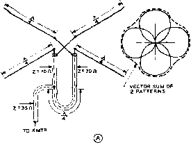 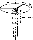 COAXIAL LINE TO TRANSMITTER TRANSFORMER LOW Z TRANSMISSION LINE © Figure 1 THREE NONDIRECTIONAL, HORIZONTALLY POLARIZED ANTENNAS radiation at the very low elevation angles are not recommended for v-h-f and u-h-f work. It is for this reason that the horizontal dipole and horizontally-disposed colinear arrays are generally unsuitable for work on rhese frequencies. Arrays using broadside or end-fire elements do concentrate radiation at low elevation angles and are recommended for v-h-f work. Arrays such as the lazy-H, Sterba curtain, flat-top beam, and arrays with parasiti-cally excited elements are recommended for this work. Dimensions for the first three types of arrays may be determined from the data given in the previous chapter, and reference maybe made to the Table of Wavelengths given in this chapter. Arrays using vertically-stacked horizontal dipoles, such as are used by commercial television and FM stations, are capable of giving high gain without a shaф horizontal radiation pattern. If sets of crossed dipoles, as shown in figure lA, are fed 90° out of phase the resulting system is called a turnstile antenna. The 90° phase difference between sets of dipoles may be obtained by feeding one set of dipoles with a feed line which is one-quarter wave longer than the feed line to the other set of dipoles. The field strength broadside to one of the dipoles is equal to the field from that dipole alone. The field strength at a point at any other angle is equal to the vector sum of the fields from rhe two dipoles at that angle. A nearly circular horizontal pattern is produced by this antenna. A second antenna producing a uniform, horizontally polarized pattern is shown in figure IB. This antenna employs three dipoles bent to form a circle. All dipoles are excited in phase, and are center fed. A bazooka is included in the system to prevent unbalance in the coaxial feed system. A third nondirectional antenna is shown in figure 1С. This simple antenna is made of two half-wave elements, of which the end quarter-wavelength of each is bent back 90 degrees. The pattern from this antenna is very much like that of die turnstile antenna. The field ftom the two quarter-wave sections that are bent back are additive because they are 180 degrees out of phase and are a half wavelength apart. The advantage of this antenna is the simplicity of its feed system and construction. 24-3 Simple Verfical-Polarized Antennas For general coverage with a single antenna, a single vertical radiator is commonly employed. A two-wire open transmission line is not suitable for use with this type antenna, and coaxial polyethylene feed line such as RG-8/U is to be recommended. Three practical methods of feeding the radiator with concentric line, with a minimum of current induced in the outside of the line, are shown in figure 2. Antenna (A) is known as the sleeve antenna, the lower half of the radiator being a large piece of pipe up through which the concentric feed line is run. At (B) is shown the ground-plane vertical, and at (C) a modification of this latter antenna. The radiation resistance of the ground-plane vertical is approximately 30 ohms, which is not a standard impedance for coaxial line. To obtain a good match, the firsr quarter wavelength of feeder may be of 52 ohms surge impedance, and the remainder of the line of approximately 75 ohms impedance. Thus, the first quarter-wave section of line is used as a 1 ... 44 45 46 47 48 49 50 ... 80 |
|
© 2026 AutoElektrix.ru
Частичное копирование материалов разрешено при условии активной ссылки |