 |
 |
 |
| Главная Журналы Популярное Audi - почему их так назвали? Как появилась марка Bmw? Откуда появился Lexus? Достижения и устремления Mercedes-Benz Первые модели Chevrolet Электромобиль Nissan Leaf |
Главная » Журналы » Simple coaxial reflectometer 1 ... 45 46 47 48 49 50 51 ... 80 HANDBOOK Vertically Polarized Arrays 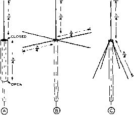 Figure 2 THREE VERTICALLY-POLARIZED LOW-ANGLE RADIATORS Shown ot (A) is the sleeve or hypodermic type of radiator. At (B) is shown the ground-plane vertical, and ( C) sbows о modification of this antenna system which increases the feed-point impedance to a value such that the system may be fed directly from a coaxial line with no standing waves On the feed line. matching transformer, and a good match is obtained. In actual practice the antenna would consist of a quarter-wave rod, mounted by means of insulators atop a pole or pipe mast. Elaborate insulation is not required, as the voltage at the lower end of the quarter-wave radiator is very low. Self-supporting rods from 0.25 to 0.28 wavelength would be extended out, as in the illustration, and connected together. As the point of connection is effectively at ground potential, no insulation is required; the horizontal rods may be bolted directly to the supporting pole or mast, even if of metal. The coaxial line should be of the low loss type especially designed for v-h-f use. The outside connects to the junction of the radials, and the inside to the bottom end of the vertical radiator. An antenna of this type is moderately simple to construct and will give a good account of itself when fed at the lower end of the radiator directly by the 52-ohm RG-8/U coaxial cable. Theoretically the standing-wave ratio will be approximately 1.5-to-l but in practice this moderate s-w-r produces no deleterious effects, even on coaxial cable. The modification shown in figure 2C permits matching to a standard 50- or 70-ohm flexible coaxial cable without a linear transformer. If the lower rods hug the liae and supporting mast rather closely, the feed-point impedance is about 70 ohms. If they are bent out to form an angle of about 30° with the support pipe the impedance is about 50 ohms. The number of radial legs used in a ground-plane antenna of either type has an important effect on the feed-point impedance and upon the radiation characteristics of the antenna system. Experiment has shown that three radials is the minimum number that should be used, and that increasing the number of radials above six adds substantially nothing to the effectiveness of the antenna and has no effect on the feed-point impedance. Experiment has shown, however, that the radials should be slightly longer than one-quarter wave for best results. A length of 0.28 wavelength has been shown to be the optimum value. This means that the radials for a 50-Mc. ground-plane vertical antenna should be 65 in length. Double Skeleton Cone Antenna The bandwidth of the antenna of figure 2C can be increased considerably by substituting several space-tapered rods for the single radiating element, so that the radiator and skirt are similar. If a sufficient number of rods are used in the skeleton cones and the angle of revolution is optimized for the particular type of feed line used, this antenna exhibits a very low SWR over a 2 to 1 frequency range. Such an arrangement is illustrated schematically in figure 3. A Nondirectional Half-wave elements may be Vertical Array stacked in the vertical plane to provide a non-directional pattern with good horizontal gain. An array made up of four half-wave vertical elements is shown in figure 4A. This antenna provides a circular pattern with a gain of about 4.5 db over a vertical dipole. It may be fed with 300-ohm TV-type line. The feedline should be conducted in such a way that the vertical portion of the line is at least one-half wavelength away from the vertical antenna elements. A suitable mechanical assembly is shown in figure 4B for the 144-Mc. and 235-Mc. amateur bands. 24-4 The Discone Antenna The Discone antenna is a vertically polarized omnidirectional radiator which has very broad band characteristics and permits a simple, rugged structure. This antenna presents a substantially uniform feed-point impedance, suitable for direct connection of a coaxial line, over a range of several octaves. Alsg, the vertical pattern is suitable for ground-wave TOP APEX CONNECTS TO INNER CONNECTOR LOWER APEX CONNECTS TO OUTER CONDUCTOR  APICES FORMED OF SHEET METAL RS-e/U CABLE Figure 3 THE DOUBLE SKELETON CONE ANTENNA A skeleton cone has been substituted for the single element radiator of figure 2C. This greatly increases the bandwidth. If at least 10 e/ements ore used for each skeleton cone and the angle of revolution ond element length ore optimized, a low SWR con be obtained over a frequency ronge of at least two octaves. To obtain this order of bandwidth, the element length L should be approximately 0,2 wavelength ot the lower frequency end of the band, ond the angle of revolution optimized for the lowest maximum VSWR within the frequency range to be covered. A greater improvement In the impedance-frequency characteristic can be achieved by adding e/ements than by increasing the diameter of the elements. With only 3 e/ements per cone ond a much smaller angle of revolution a low SWR can be obtained over a frequency range of approximately 1,3 to 1.0 when the element lengths are optimized. work over several octaves, the gain varying only slightly over a very wide frequency range. Commercial versions of the Discone antenna for various applications are manufactured by the Federal Telephone and Radio Corporation, A Discone type antenna for amateur work can be fabricated from inexpensive materials with ordinary hand tools. A Discone anteima suitable for multi-band amateur work in the v-h/u-h-f range is shown schematically in figure 5A. The distance D should be made approximately equal to a free-space quarter wavelength at the lowest oper- 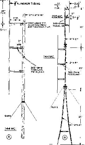 Figure 4 NONDIRECTIONAL ARRAYS FOR 144 MC AND 235 MC. On right is shown two band installation. The whole system may easily be dissembled and carried on a ski-rack atop о car for portable use. ating frequency. The antenna then will perform well over a frequency range of at least 8 to 1. At certain frequencies within this range the vertical pattern will tend to lift slightly, causing a slight reduction in gain at zero angular elevation, but the reduction is very slight. Below the frequency at which the slant height of the conical skirt is equal to a free-space quarter wavelength the standing-wave ratio starts to climb, and below a frequency approximately 20 per cent lower than this the standing-wave ratio climbs very rapidly. This is termed the cut off frequency of the antenna. By making the slant height approximately equal to a free-space quarter wavelength at the lowest frequency employed (refer to chart), a HANDBOOK Discone Antenna 483 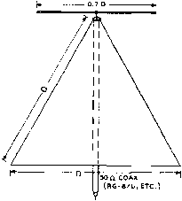 Figure 5A THE DISCONE BROAD-BAND RADIATOR This antenna system radiates a vertically polarized wave over a very wide frequency range. The disc may be mode of solid metal sheet, о group of radials, or wire screen; the cone may best be constructed by forming a sheet of thin aluminum. A sin-gle antenna moy be used for operation on the 50, 144, ond 220 Mc. omofeur bonds. Tbe dimension D is determined by the lowest frequency to be employed, and is given in the chart of figure SB. о Э (Л LJ 1.5 2 DIN FEET 2.5 3 DESIGN Figure SB CHART FOR THE DISCONE ANTENNA of the skirt directly to an effective ground plane such as the top of an automobile. 24-5 Helical Beam Antennas VSWRof less than 1.5 will be obtained throughout the operating range of the antenna. The Discone antenna may be considered as a cross between an electromagnetic horn and an inverted ground plane unipole antenna. It looks to the feed line like a properly terminated high-pass filter. Construction Details The top disk and the conical skirt may be fabricated either from sheet metal, screen (such as hardware cloth ), or 12 or more spine radials. If screen is used a supporting framework of rod or tubing will be necessary for mechanical strength except at the higher frequencies.. If spines are used, they should be terminated on a stiff ring for mechanical strength except at the higher frequencies. The top disk is supported by means of three insulating pillars fastened to the skirt. Either polystyrene or low-loss ceramic is suitable for the purpose. The apex of the conical skirt is grounded to the supporting mast and to the outer conductor of the coaxial line. The line is run down through the supporting mast. An alternative arrangement, one suitable for certain mobile applications, is to fasten the base Most v-h-f and u-h-f antennas are either vertically polarized or horizontally polarized (plane polarization). However, circularly polarized anteimas have interesting characteristics which may be useful for certain applications. The installation of such an antenna can effectively solve the problem of horizontal vs. vertical polarization. A circularly polarized wave has its energy divided equally between a vertically polarized component and a horizontally polarized component, the two being 90 degrees out of phase. The circularly polarized wave may be either left handed or right handed, depending upon whether the vertically polarized component leads or lags the horizontal component. A circularly polarized antenna will respond to any plane polarized wave whether horizontally polarized, vertically polarized, or diagonally polarized. Also, a circular polarized wave can be received on a plane polarized antenna, regardless of the polarization of the latter. When using circularly polarized antennas at both ends of the circuit, however, both must be left handed or both must be right handed. This offers some interesting possibilities with regard to reduction of QRM. At TRANSMIT 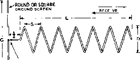 COAX FEED POINT (RG-83/u) AT CENTER OF GROUND SCREEN G 0. s X L- 1.44 X CONDUCTOR OIA.= APPRDX. 0.17X A=WAVELENGTH IN FREE SPACE Figure 6 THE HELICAL BEAM ANTENNA This fype of directional anfenna system gives excellertt performance over a frequency range of 1.7 to 1.8 to I. Its dimensions are such that it ordinarily is not practicable, however, for use os a rotatable array on frequencies below about 100 Mc. The center conductor of the feed line should pass through the ground screen for connection to the feed point. The outer conductor of the coaxial line should be grounded to fhe ground screen. the time of writing, there has been no standardization of the twist for general amateur work. Perhaps the simplest antenna configuration for a directional beam antenna having circular polarization is the helical beam popularized by Dr. John Kraus, W8JK. The antenna consists simply of a helix working against a ground plane and fed with coaxial line. In the u-h-f and the upper v-h-f range the physical dimensions are sufficiently small to permit construction of a rotatable structure without much difficulty. When the dimensions are optimized, the characteristics of the helical beam antenna are such as to qualify it as a broad band antenna. An optimized helical beam shows little variation in the pattern of the main lobe and a fairly uniform feed point impedance averaging approximately 125 ohms over a frequency range of as much as 1.7 to 1. The direction of electrical twist (right or left handed) depends upon the direction in which the helix is wound. A six-turn helical beam is shown schematically in figure 6. The dimensions shown will give good performance over a frequency range of plus or minus 20 per cent of the design frequency. This means that the dimensions are not especially critical when the array is to be used at a single frequency or over a narrow band of frequencies, such as an amateur band. At the design frequency the beam width is about 50 degrees and the power gain about 12 db, referred to a non-directional circularly polarized antenna. The Ground Screen For the frequency range 100 to 500 Mc. a suitable ground screen can be made from chicken wire poultry netting of 1-inch mesh, fastened to a round or square frame of either metal or wood. The netting should be of the type that is galvanized after weaving. A small, sheet metal ground plate of diameter equal to approximately D/2 should be centered on the screen and soldered to it. Tin, galvanized iron, or sheet copper, is suitable. The outer conductor of the RG-63/U (125 ohm) coax is connected to this plate, and the inner conductor contacts the helix through a hole in the center of the plate. The end of the coax should be taped with Scotch electrical tape to keep water out. The Helix It should be noted that the beam proper consists of six full turns. The start of the helix is spaced a distance of S/2 from the ground screen, and the conductor goes directly from the center of the ground screen to the start of the helix. Aluminum tubing in the SO (soft) grade is suitable for the helix. Alternatively, lengths of the relatively soft aluminum electrical conduit may be used. In the v-h-f range it will be necessary to support the helix on either two or four wooden longerons in order to achieve sufficient strength. The longerons should be of as small cross section as will provide sufficient rigidity, and should be given several coats of varnish. The ground plane butts against the longerons and the whole assembly is supported from the balance point if it is to be rotated. Aluminum tubing in the larger diameters ordinarily is not readily available in lengths greater than 12 feet. In this case several lengths can be spliced by means of short telescoping sections and sheet metal screws. The tubing is close wound on a drum and then spaced to give the specified pitch. Note that the length of one complete turn when spaced is somewhat greater than the circumference of a circle having the diameter D. Brood-Bond A highly useful v-h-f helical 144 to 225 Mc. beam which will receive sig-Helicol Beom nals with good gain over the complete frequency range from 144 through 225 Mc. may be constructed by using the following dimensions (180 Mc. design center): HANDBOOK Helical Beam Antenna 485 D............................22 in. S.........................16V in. G............................53 in. Tubing o.d.................1 in. The D and S dimensions are to the center of the tubing. These dimensions must be held rather closely, since the range from 144 through 225 Mc. represents just about the practical limit of coverage of this type of antenna system, High-Band Note that an array constructed TV Coverage with the above dimensions will give unusually good high-band TV reception in addition to covering the 144-Mc, and 220-Mc. amateur bands and the taxi and police services. On the 144-Mc. band the beam width is approximately 60 degrees to the half-power points, while the power gain is approximately 11 db over a non-directional circularly polarized antenna. For high-band TV coverage the gain will be 12 to 14 db, with a beam width of about 50 degrees, and on the 220-Mc. amateur band the beam width will be about 40 degrees with a power gain of approximately 15 db. The antenna system will receive vertically polarized or horizontally polarized signals with equal gain over its entire frequency range. Conversely, it will transmit signals over the same range, which then can be received with equal strength on either horizontally polarized or vertically polarized receiving antennas. The standing-wave ratio will be very low over the complete frequency range if RG-63/U coaxial feed line is used. 24-6 The Corner-Reflector and Horn-Type Antennas The corner-reflector antenna is a good directional radiator for the v-h-f and u-h-f region. The antenna may be used with the radiating element vertical, in which case the directivity is in the horizontal or azimuth plane, or the system may be used with the driven element driven dipole: 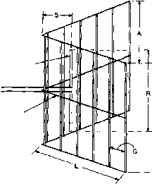 supporting MEMBER Figure 7 CONSTRUCTION OF THE CORNER REFLECTOR ANTENNA Such on antenna is capable of giving high gain with a minimum of complexity in the radiating system. It may be used either with horizontal or vertical polarization. Design data for the antenna is given in the Corner-Reflector Design Table. horizontal in which case the radiation is horizontally polarized and most of the directivity is in the vertical plane. With the antenna used as a horizontally polarized radiating system the array is a very good low-angle beam array although the nose of the horizontal pattern is still quite sharp. When the radiator is oriented vertically the corner reflector operates very satisfactorily as a direction-finding antenna. Design data for the corner-reflector antenna is given in figure 7 and in the chart Corner-Reflector Design Data, The planes which make up the reflecting corner may be made of solid sheets of copper or aluminum for the u-h-f bands, although spaced wires with the ends soldered together at top and bottom may be used as the reflector on the lower frequencies. CORNER-REFLECTOR DESIGN DATA
NOTE: Refer fo figure 7 for construction of corner-reflector antenna. 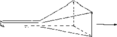 WAVE UUIDE (A) UHF HORN ANTENNA 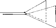 450-ohm LINE (D VHF HORIZONTALLY POLARIZED HORN Figure 8 TWO TYPES OF HORN ANTENNAS The two sided horn of Figure 8B may be fed by meons of an open-wire transmission line. Copper screen may also be used for the reflecting planes. The values of spacing given in the corner-reflector chart have been chosen such that the center impedance of the driven element would be approximately 70 ohms. This means that the element may be fed directly with 70-ohm coaxial line, or a quarter-wave matching transformer such as a Q section may be used to provide an impedance match between the center-impedance of the element and a 460-ohm line constructedof no. 12 wire spaced 2 inches. In many v-h-f antenna systems, waveguide transmission lines are terminated by pyramidal horn antennas. These horn antennas (figure 8A) will transmit and receive either horizontally or vertically polarized waves. The use of waveguides at 144 Mc. and 235 Mc, however, is out of the question because of the relatively large dimensions needed for a waveguide operating at these low frequencies. A modified type of horn antenna may still be used on these frequencies, since only one particular plane of polarization is of interest to the amateur. In this case, the horn antenna can be simplified to two triangular sides of the pyramidal horn. When these two sides are insulated from each other, direct excitation at the apex of the horn by a two-wire transmission line is possible. In a normal pyramidal horn, all four triangular sides are covered with conducting material, but when horizontal polarization alone is of interest (as in amateur work) only the vertical areas of the horn need be used. If vertical polarization is required, only the horizontal areas 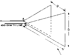 ANGLE BETWEEN SIDES OF HORN = eO D.
two sides made of wire mesh Figure 9 THE 60° HORN ANTENNA FOR USE ON FREQUENCIES ABOVE 144 MC of the horn are employed. In either case, the system is unidirectional, away from the apex of the horn. A typical horn of this type is shown in figure 8B. The two metallic sides of the horn are insulated from each other, and the sides of the horn are made of small mesh chicken wire or copper window screening. A pyramidal horn is essentially a high-pass device whose low frequency cut-off is reached when a side of the horn is 14 wavelength. It will work up to infinitely high frequencies, the gain of the horn increasing by 6 db every time the operating frequency is doubled. The power gain of such a horn compared to a 14 wave dipole at frequencies higher than cutoff is; 8.4 A Power gain (db) =- where A is the frontal area of the mouth of the hocn. For the 60 degree horn shown in figure 88 the formula simplifies to: Powet gain (db) = 8.4 D, when D is expressed in terms of wavelength When D is equal to one wavelength, the power gain of the horn is approximately 9 db. The gain and feed point impedance of the 60 degree horn are shown in figure 9. A 450 ohm open wire TV-type line may be used to feed the horn. 24-7 VHF Horizontal Rhombic Antenna For v-h-f transmission and reception in a fixed direction, a horizontal rhombic permits HANDBOOK VHF Rhombic 487 ш l d Z < э 55° О 50< TOP VIEW 4Л 64 ex SIDE LENGTH, S 10Л 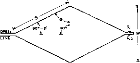 0 = TILT ANGLE Rl. Нг= 390 OHMS EACH NON-inducnve Figure 10 V-H-F RHOMBIC ANTENNA DESIGN CHART The optimum tilt angle (see figure ii) for zero-angle radiation depends upon the length of the sides. 10 to 16 db gain with a simpler construction than does a phased dipole array, and has the further advantage of being usehil over a wide frequency range. Except at the upper end of the v-h-f range a rhombic array having a worthwhile gain is too large to be rotated. However, in locations 75 to 150 miles from a large metropolitan area a rhombic array is ideally suited for working into the city on extended (horizontally polarized) ground-wave while at the same time making an ideal antenna for TV reception. The useful frequency range of a v-h-f rhombic array is about 2 to 1, or about plus 40% and minus 30% from the design frequency. This coverage is somewhat less than that of a high-frequency rhombic used for sky-wave communication. For ground-wave transmission or reception the only effective vertical angle is that of the horizon, and a frequency range greater than 2 to 1 cannot be covered with a rhombic array without an excessive change in the vertical angle of maximum radiation or response. The dimensions of a v-h-f rhombic array are determined from the design frequency and figure 10, which shows the proper tilt angle (see figure 11) for a given leg length. The gain of a rhombic array increases with leg length. There is not much point in constructing a v-h-f rhombic array with legs shorter than about 4 wavelengths, and the beam width begins to become excessively вЬаф for leg lengths greater than about 8 wavelengths. Л leg length of 6 wavelengths is a good compromise between beam width and gain. The tilt angle given in figure 10 is based upon a wave angle of zero degrees. For leg lengths of 4 wavelengths or longer, it will be Figure 11 V-H-F RHOMBIC ANTENNA CONSTRUCTION necessary to elongate the array a few per cent (pulling in the sides slightly) if the horizon elevation exceeds about 3 degrees. Table I gives dimensions for two dual purpose rhombic arrays. One covers the 6-meter amateur band and the low television band. The other covers the 2-meter amateur band, the high television band, and the ly-meter amateur band. The gain is approximately 12 db over a matched half wave dipole and the beam width is about 6 degrees. The Feed Line The recommended feed line is an open-wire line having a surge impedance between 450 and 600 ohms. With such a line the VSWR will be less than 2 to 1. A line with two-inch spacing is suitable for frequencies below 100 Mc, but one-inch spacing (such as used in the Gonset Line for TV installations) is recommended for higher frequencies. The Termination If the array is to be used only for reception, a suitable termination consists of two 390-ohm carbon re-
TABLE I, sistors in series. If 2-watt resistors are employed, this termination also is suitable for transmitter outputs of 10 watts or less. For higher powers, however, resistors having greater dissipation with negligible reactance in the upper v-h-f range are not readily available. For powers up to several hundred watts a suitable termination consists of a lossy line consisting of stainless steel wire (corresponding to no. 24 or 26 B&S gauge) spaced 2 inches, which in turn is terminated by two 390-ohm 2-watt carbon resistors. The dissi-pative line should be at least 6 wavelengths long. 24-8 Multi-Element V-H-F Beam Antennas
R-REFLECTOR 40 LONG 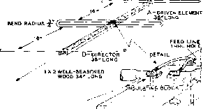 6AIN 7.5DB (20L0NG FOR 1-METERS) FLATTEN ENDS OF TUBING AND DRILL FOR 6/32 SCREWS CJi> WOOD BOOM У/  The rotary multi-element beam is undoubtedly the most popular type of v-h-f antenna in use. In general, the design, assembly and tuning of these antennas follows a pattern similar to the larger types of rotary beam antennas used on the lower frequency amateur bands. The characteristics of these low frequency beam antennas are discussed in the next chapter of this Handbook, and the information contained in that chapter applies in general to the v-h-f beam antennas discussed herewith. A Simple Three The simplest v-h-f beam for Element Beom the beginner is the three-ele-Antenna ment Yagi array illustrated in figure 12. Dimensions are given for Yagis cut for the 2-meter and \Vir meter bands. The supporting boom for the Yagi may be made from a smoothed piece of 1 x 2 wood. The wood should be reasonably dry and should be painted to prevent warpage from exposure to sun and rain. The director and reflector are cut from lengths of copper tubing, obtainable from any appliance store that does service work on refrigerators. They should be cut to length as noted in figure 12. The elements should then be given a coat of aluminum paint. Two small holes are drilled at the center of the reflector and director and these elements are bolted to the wood boom by means of two 1 wood screws. These screws should be of the plated, or rust-proof variety. The driven element is made of a 78 length of /i copper tubing, the ends bent back upon each other to form a folded dipole. If the tubing is packed with fine sand and the bending points heated over a torch, no trouble will be had in the bending process. If the tubing does collapse when it is bent, the break may be repaired with a heavy-duty soldering iron. The Figure 12 SIMPLE 3.ELEMENT BEAM FOR 2 AND IW METERS driven element is next attached to the center of the wood boom, mounted atop a small insulating plate made of bakelite, micarta or some other non-conducting material. It is held in place in the same manner as the parasitic elements. The two free ends of the folded dipole are hammered flat and drilled for a 6-32 bolt. These bolts pass through both the insulating block and the boom, and hold the free tips of the element in place. A length of 75-ohm Twin-Lead TV-type line should be used with this beam antenna. It is connected to each of the free ends of the folded dipole. If the .antenna is mounted in the vertical plane, the 75-ohm line should be brought away from the antenna for a distance of four to six feet before it drops down the tower to lessen interaction between the antenna elements and the feed line. The complete antenna is light enough to be turned by a TV rotator. A simple Yagi antenna of this type will provide a gain of 7 db over the entire 2-meter or ly-meter band, and is highly recommended as an easy-to-build beam for the no vice or beginner. An 8-Element Tippable Array for 144 Mc. Figures 13 and 14 illustrate an 8-eIement rotary array for use on the 144-Mc. amateur band. This array is tippable to obtain either horizontal or vertical polarization. It is necessary that the transmitting and receiving station use the same polarization for the ground-wave signal propagation which is characteristic of this fre- 2ND DIRECTOR 35.5 MAIN BOOMS - APPROX. O.D. 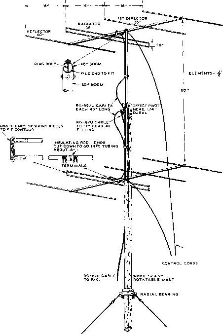 ENDS OF TUBING WOOD DOWELS INSIDE FOR STRENGTH AS SHOWN, ANTENMA IS HORIZONTALLY POLARIZED. PULL TO SWI MG MAIN BOOM 90° FOR VERTICAL POLARITY. CONSTRUCTIONAL DRAWING OF Figure 13 AN EIGHT-ELEMENT TIPPABLE 144-MC. ARRAY quency range. Although polarization has been loosely standardized in various areas of the country, exceptions are frequent enough so that it is desirable that the polarization of antenna radiation be easily changeable from horizontal to vertical. The antenna illustrated has shown a signal gain of about 11 db, representing a power gain of about 13. Although the signal gain of the antenna is the same whether it is oriented for vertical or horizontal polarization, the horizontal beam width is smaller when the antenna is oriented for vertical polarization. Conversely, the vertical pattern is the sharper when the antenna system is oriented for horizontal polarization. The changeover from one polarization to the other is accomplished simply by pulling on the 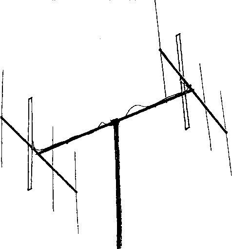 Figure 14 THE EIGHT-ELEMENT 144.MC ARRAY IN A HORIZONTAL POSITION appropriate cord. Hence, the operation is based on the offset head sketched in figure 13- Although a wood mast has been used, the same system may be used with a pipe mast. The 40-inch lengths of RG-59/U cable (electrically wavelength) running from the center of each folded dipole driven element to the coaxial T-junction allow enough slack to permit free movement of the main boom when changing polarity. Type RG-8/U cable is run from the T-junction to the operating position. Measured standing-wave ratio was less than 2:1 over the 144 to 148 Mc. band, with the lengths and spacings given in figure 13. Construction of the Array Most of the constructional aspects of the antenna array are self-evident from figure 13. However, the pointers given in the following paragraphs will be of assistance to those wishing to reproduce the array. The drilling of holes for the small elements should be done carefully on accurately marked centers. A small angular error in the drilling of these holes will result in a considerable misalignment of the elements after the array is assembled. The same consideration is true of the filing out of the rounded notches in the ends of the main boom for the fitting of the two antenna booms. Short lengths of wood dowel are used freely in the construction of the array. The ends of the small elements are plugged with an inch or so of dowel, and the ends of the antenna booms are similarly treated with larger discs pressed into place. 1 ... 45 46 47 48 49 50 51 ... 80 |
|||||||||||||||||||||||||||||||||||||||||||||||||||||||||||||||||||||||||||||||||||||||||||||||||||||||||||||||||||||||||||||||||||||||||||||||||||||||||||||||||||||||||||||||||||||||||||||||
|
© 2026 AutoElektrix.ru
Частичное копирование материалов разрешено при условии активной ссылки |