 |
 |
 |
| Главная Журналы Популярное Audi - почему их так назвали? Как появилась марка Bmw? Откуда появился Lexus? Достижения и устремления Mercedes-Benz Первые модели Chevrolet Электромобиль Nissan Leaf |
Главная » Журналы » Simple coaxial reflectometer 1 ... 46 47 48 49 50 51 52 ... 80 The ends of the folded dipoles are made in the following manner: Drive a length of dowel into the short connecting lengths of aluminum tubing. Then drill down the center of the dowel with a clearance hole for the connecting screw. Then shape the ends of the connecting pieces to fit the sides of the element ends. After assembly the junctions may be dressed with a file and sandpaper until a smooth fit is obtained. The mast used for supporting the array is a 30-foot spliced 2 by 2. A large discarded ball bearing is used as the radial load bearing and guy-wire termination. Enough of the upper-mast corners were removed with a draw-knife to permit sliding the ball bearing down about 9 feet from the top of the mast. The bearing then was encircled by an assembly of three pieces of dural ribbon to form a damp, with ears for tightening screws and attachment of the guy wires. The bearing then was greased and covered with a piece of auto inner tube to serve as protection from the weather. Another junk-box bearing was used at the bottom of the mast as a thrust bearing. The main booms were made from Ji-inch aluminum electrical conduit. Any size of small tubing will serve for making the elements. Note that the main boom is mounted at the balance center and not necessarily at the physical center. The pivot bolt in the offset head should be tightened sufficiently that there will be adequate friction to hold the array in position. Then an additional nut should be placed on the pivot bolt as a lock. In connecting the phasing sections between the T-junction and the centers of the folded dipoles, it is important that the center conductors of the phasing sections be connected to the same side of the driven elements of the antennas. In other words, when the antenna is oriented for horizontal polarization and the center of the coaxial phasing section goes to the left side of the top antenna, the center conductor of the other coaxial phasing section should go to the left side of the bottom antenna. The Screen Beam This highly effective ro-for 2 Meters tary array for the 144 Mc. amateur band was designed by the staff of the Experimental Physics Laboratory, The Hague, Netherlands for use at the 2 meter experimental station PEIPL. The array consists of 10 half wave radiators fed in phase, and arranged in two stacked rows of five radiators. 0.2 wavelength behind this plane of radiators is a reflector screen, meas- uiittg approximately 15 x 9 in size. The antenna provides a power gain of 15 db, and a front to back ratio of approximately 28 db.  ALL JOINTS WELDED Figure 15 DETAIL OF LAYOUT AND DIMENSIONS OF BEAM ASSEMBLY OF PEiPL The 10 dipoles are fed in phase by means of a length of balanced transmission line, a quarter-wave matching transformer, and a ba-lun. A 72-ohm coaxial line couples the array to die transmitter. A drawing of the array is shown in figure 15. The reflecting screen measures 14 9 high by 8 4 wide, and is made of welded 14 diameter steel tubing. Three steel reinforcing bars are welded horizontally across the framework directly behind each pair of horizontal dipoles. The intervening spaces are filled with lengths of no. 12 enamel-coated copper wire to complete the screen. The spacing between the wires is 2 . Four cross braces are welded to the corners of the frame for additional bracing, and a single vertical rod runs up the middle of the frame. The complete, welded frame is shown in figure 15. The no. 12 screening wires are run between 6-32 bolts placed in holes drilled in each outside vertical member of the frame. The anteima assembly is supported away from the reflector screen by means of ten lengths of Уг steel tubing, each Г 3l4 long. WOOD BLOCK  support Figure 16 THE MOUNTING BLOCK FOR EACH SET OF ELEMENTS These tubes are welded onto the center tube of each group of three horizontal bracing tubes, and are so located to support the horizontal dipole at its exact center. The dipoles are attached to the supporting rods by means of small phenolic insulating blocks, as shown in figure 16. The radiators are therefore insulated from the screen reflector. The inner tips of the radiators are held by small polystyrene blocks for rigidity, and are cross connected to each other by a transposed length of TV-type 400 ohm open wire line. The entire array Is fed at the point A-A, illustrated in figure 15. The matching system for the beam is mounted behind the reflector screen, and is shown in figure 17. A quarter-wave transformer (B) drops the relatively high impedance of the antenna array to a suitable value for the low impedance balun (D). An adjustable matching stub (C) and two variable capacitors (Ci and Cj) are employed for impedance matching. The two variable capacitors are mounted in a brasstubinu a  TRANSFORMER-B SHORTING BAR - С Cl & c2 = 50JJJUF WATERTIGHT COMPARTMENT BALUN-D I- SHORTING BAR- D COPPER TUBING 72aC0AX CABLE Figure 17 THE MATCHING UNIT IN DETAIL FOR THE PE1PL BEAM DESIGN, WHICH ALLOWS THE USE OF 72.0HM COAX 350V S.  190 iso ito* 1*0 Figure 18 HORIZONTAL RADIATION PATTERN OF THE PE1PL ARRAY. THE FRONT-TO-BACK RATIO IS ABOUT 28 db IN AMPLITUDE, AND THE FORWARD GAIN APPROXIMATELY 15 db. watertight box, with the balun and matching stubs entering the bottom and top of the box, respectively. The matching procedure is carried out by the use of a standing wave meter (SWR bridge). A few watts of power are f e d to the array through the SWR meter, and the setting of the shorting stub on С and the setting of the two variable capacitors are adjusted for lowest SWR at the chosen operating frequency. The capacity settings of the two variable capacitors should be equal. The final adjustment is to set the shorting stub of the balun (D) to remove any residual reactance that might appear on the transmission line. With proper adjustment, the VSWR of the array may be held to less than 1.5 to 1 over a 2 megacycle range of the 2-meter band. The horizontal radiation pattern of this array is shown in figure 18. Long Yogi For a given power gain, the Antennas Y g? antenna can be built lighter, more compact, and with less wind resistance than any other type.  DRIVEN ELEMENT ОЙ ILL HOLES THUOUQH BOOM AND PASS ELEMENTS THPOUSH HOLES. BOOM LENOTH = 24, DIAM. 1- GAIN= 16.1 DB
Figure 19 DESIGN DIMENSIONS FOR A 2-METER LONG YAGI ANTENNA On the other hand, if a Yagi array of the same approximate size and weight as another antenna type is built, it will provide a higher order of power gain and directivity than that of the other antenna. The power gain of a Yagi antenna increases directly with the physical length of the array. The maximum practical length is entirely a mechanical problem of physically supporting the long series of director elements, although when the array exceeds a few wavelengths in length the element lengths, spacings, and Qs become more and more critical. The effectiveness of tbe array depends upon a proper combination of the mutual coupling loops between adjacent directors and between the first director and the driven element. Practically all work on Yagi antennas with more than three or four elements has been on an experimental, cut-and-try basis. Figure 19 provides dimensions for a typical Long Yagi antenna for the 2-meter VHF band. Note that all directors have the same physical length. If the long Yagi is designed so that the directors gradually decrease in length as they progress from the dipole bandwidth will be increased, and both side lobes and forward gain will be reduced. One advantage gained from staggered director length is that the array can be shortened and lengthened by adding or taking away directors without the need for retuaing the remaining group of parasitic elements. When all directors are the same length, they must be all shortened en masse as the array is lengthened, and vice-versa when the array is shortened. A full discussion of Long Yagi antennas,. including complete design and construction information may be had in the VHF Handbook, available through Radio Publications, Inc., Wilton., Conn. Rotary Beams The rotatable antenna array has become almost standard equipment for operation on the 28-Mc. and 50-Mc. bands and is commonly used on the 14-Mc. and 21-Mc. bands and on those frequencies above 144 Mc. The rotatable array offers many advantages for both military and amateur use. The directivity of the antenna types commonly employed, particularly the unidirectional arrays, offers a worthwhile reduction in interference from undesired directions. Also, the increase in the ratio of low-angle radiation plus the theoretical gain of such arrays results in a relatively large increase in both the transmitted signal and the signal intensity from a station being received. A significant advantage of a rotatable antenna array in the case of the normal station is that a relatively small amount of space is required for erection of the antenna system. In fact, one of the best types of installation uses a single telephone pole with the rotating structure holding the antenna mounted atop the pole. To obtain results in all azimuth directions from fixed arrays comparable to the gain and directivity of a single rotatable three-element parasitic beam would require several acres of surface. There are two normal configurations of radiating elements which, when horizontally polarized, will contribute to obtaining a low angle of radiation. These configurations are the end-fire array and the broadside array. The con- ventional three- or four-element rotary beam may properly be called a unidirectional parasitic end-fire array, and is actually a type of yagi array. The flat-top beam is a type of bidirectional end-fire array. The broadside type of array is also quite effective in obtaining low-angle radiation, and although widely used in FM and TV broadcasting has seen little use by amateur stations in rotatable arrays. 25-1 Unidirectional Parasitic End-Fire Arrays (Yogi Type) If a single parasitic element is placed on one side of a driven dipole at a distance of from 0.1 to 0.25 wavelength the parasitic element can be tuned to make the array substantially unidirectional. This simple array is termed a two element parasitic beam. 25-2 The Two Element Beam The two element parasitic beam provides the greatest amount of gain per unit size of any array commonly used by radio amateurs. Parasitic Arrays 495 < 2 (5
0.1 0.1S 0.2 0,25 ELEMENT SPACING (X) Figure 1 GAIN VS ELEMENT SPACING FOR A TWO-ELEMENT CLOSE-SPACED PARASITIC BEAM ANTENNA WITH PARASITIC ELE-MENT OPERATING AS A DIRECTOR OR REFLECTOR I О 10 25 Ш 20 < a. 5
0.1 0.15 0.2 а25 ELEMENT SPACING fX) Figure 2 RADIATION RESISTANCE AS A FUNCTION OF ELEMENT SPACING FOR A TWO-ELE-MENT PARASITIC ARRAY Such an antenna is capable of a signal gain of 5 db over a dipole, with a front-to-back ratio of 7 db to 15 db, depending upon the adjustment of the parasitic element. The parasitic element may be used either as a director or as a reflector. The optimum spacing for a reflector in a two-element array is approximately 0.13 wavelength and with optimum adjustment of the length of the reflector a gain of approximately 5 db will be obtained, with a feed-point resistance of about 25 ohms. If the parasitic element is to be used as a director the optimum spacing between it and the driven element is 0.11 wavelength. The gain will theoretically be slightly greater than with the optimum adjustment for a reflector (about 5.5 db) and the radiation resistance will be in the vicinity of 17 ohms. The general characteristics of a two-element parasitic array may be seen in figures 1, 2 and 3. The gain characteristics of a two-element array when the parasitic element is used as a director or as a reflector are shown. It can be seen that the director provides a maximum of 5.3 db gain at a spacing of slightly greater than O.i wavelength from the antenna. In the interests of greatest power gain and size conservation, therefore, the choice of a parasitic director would be wiser than the choice of a parasitic reflector, although the gain difference between the two is small. Figure 2 shows the relationship between the element spacing and the radiation resist- ance for die two element parasitic array for both the reflector and the director case. Since the optimum antenna-director spacing for maximum gain results in an antenna radiation resistance of about 17 ohms, and the optimum antenna-reflector spacing for maximum gain results in an antenna radiation resistance of about 25 ohms, it may be of advantage in some instances to choose the antenna with the higher radiation resistance, assuming other factors to be equal. Figure 3 shows the front-to-back ratio for the two element parasitic array for both the reflector and director cases. To produce these curves, the elements were tuned for maximum gain of the array. Better front-to-back ratios may be obtained at the expense of array gain, if desired, but the general shape of the curves remains the same. It can be readily observed that operation of the parasitic element as a reflector produces relatively poor front-to-back ratios except when the element spacing is greater than 0.15 wavelength. However, at this element spacing, the gain of the array begins to suffer. Since a radiation resistance of 17 ohms is not unduly hard to match, it can be argued that the best all-around performance may be obtained from a two element parasitic beam employing 0.11 element spacing, with the parasitic element tuned to operate as a director. This antenna will provide a forward gain of 5.3 db, with a front-to-back ratio of 10 db, or slightly greater. Closer spacing than 0.11 wavelength may be employed for greater front-to-back ratios, but the radiation resistance of the array becomes quite low, the bandwidth of the array becomes very narrow, and the tuning becomes quite critical. Thus the Q of the antenna system will be increased as the spacing between the elements is decreased, and smaller optimum frequency coverage will result. Element Lengths When the parasitic element of a two-element array is used as a director, the following formulas may be used to determine the lengths of the driven element and the parasitic director, assuming an element diameter-to-length ratio of 200 to 400: Driven element length (feet) - FMc. Director length (feet) = 450 FMc. Element spacing (feet) = l? Figure 4 FIVE ELEMENT 28 MC BEAM ANTENNA AT W6SAI Antenna boom is made of twenty foot length of Sears, Roebuck Co. three-inch aluminum irrigation pipe. Spacing between elements is five feet. Elements are made of twelve foot lengths of 7/8-inch aluminum tubing, with extension tips made of 3/4-Inch tubing. Gamma matching device, element clanps, and Oxen Yoke element-to-boom clamps are made by Continental Electronics & Sound Co., Dayton 27, Ohio, Beam dimensions are taken from figure 5.  z о
0,1 o.is о.г element spacing (XI {PARASITIC ELEMENT TUNEO FOR MAXIMUM OAIn) 0.2* Fi.gure 3 FRONT-TO-BACK RATIO AS A FUNCTION OF ELEMENT SPACING FOR A TWO-ELEMENT PARASITIC ARRAY The effective bandwidth taken between the 1.5/1 standing wave points of an array cut to the above dimensions is about 2.5% of the operating frequency. This means that an array pre-cut to a frequency of 14,15 0 kilocycles would have a bandwidth of 350 kilocycles (plus or minus 175 kilocycles of the center frequency), and therefore would be effective over the whole 20 meter band. In like fashion, a 15 meter array should be pre-cut to 21,200 kilocycles. A beam designed for use on the 10-meter band would have an effective bandwidth of some 700 kilocycles. Since the 10-meter band is 1700 kilocycles in width, the array should either be cut to 28,500 kilocycles for operation in the low frequency portion of the band, or to 29,200 kilocycles for operation in the high frequency portion of the band. Operation of the antenna outside the effective bandwidth will increase the SWR on the transmission line, and noticeably degrade both the gain and front-to-back ratio performance. The height above ground also influences the F/B ratio. 25-3 The Three-Element Array The three-element array using a director, driven element, and reflector will exhibit as much as 30 db front-to-back ratio and 20 db front-to-side ratio for low-angle radiation. The theoretical gain is about 9 db over a dipole in free space. In actual practice, the array will often show 7 to 10 db apparent gain over a horizontal dipole placed the same height above ground (at 28 and 14 Mc). The use of more than three elements is desirable when the length of the supporting structure is such that spacings of approximately 0.2 wavelength between elements becomes possible. Four-element arrays are quite common on the 28-Mc. and 50-Mc. bands, and five elements are sometimes used for increased gain and discrimination. As the number of elements is increased the gain and front-to-back ratio increases but the radiation resistance decreases and the bandwidth or frequency range over which the antenna will operate without reduction in effectiveness is decreased. Material for While the elements may consist Elements of wire supported on a wood framework, self-supporting elements of tubing are much to be preferred. The latter type array is easier to construct, looks better, is no more expensive, and avoids the problem of getting sufficiently good insulation at the ends of the elements. The voltages reach such high values towards the ends of the elements that losses will be excessive, unless the insulation is excellent. The elements may be fabricated of thin-walled steel conduit, or hard drawn thin-walled copper tubing, but dural tubing is much better. Or, if you prefer, you may purchase tapered copper-plated steel tubing elements designed especially for the purpose. Kits are available complete with rotating mechanism and direction indicator, for those who desire to purchase the whole system ready to put up. Element Spacing The Optimum spacing for a two-element array is, as has been mentioned before, approximately 0.11 wavelength for a director and 0.13 wavelength for a reflector. However, when both a director and a reflector are combined with the driven element to make up a three-element array the optimum spacing is established by the bandwidth which the antenna will be required to cover. Wide spacing (of the order of 0.25 wavelength between elements) will result in greater bandwidth for a specified maximum standing-wave ratio on the anterma transmission line. Smaller spacings may be used when boom length is an important consideration, but for a specified standing-wave ratio and forward gain the frequency coverage will be smaller. Thus the Q of the antenna system will be increased as the spacing between the elements is decreased, resulting in smaller frequency coverage, and at the same time the feed-point impedance of the driven element will be decreased. For broad-band coverage, such as the range from 26.96 to 29-7 Mc. or from 50 to 54 Mc, 0.2 wavelength spacing from the driven element to each of die parasitic elements is rec- ommended. For narrower bandwidth, such as would be adequate for the 14.0 to 14.4 Mc. band or the 144 to 148 Mc. band, the radiator to parasitic element spacing may be reduced to 0.12 wavelength, while still maintaining adequate array bandwidth for the amateur band in question. Length of the Experience has shown that Parasitic Elements it is practical to cut the prarsitic elements of a three-elementparasitic array to a predetermined length before the installation of such an antenna. A pre-tuned antenna such as this will give good signal gain, adequate front-to-back ratio, and good bandwidth factor. By carefully tuning the array after it is in position the gain may be increased by a fraction of a db, and the front-to-back ratio by several db. However the slight improvement in performance is usually not worth the effort expended in tuning time. The closer the lengths of the parasitic elements are to the resonant length of the driven element, the lower will be the feed-point resistance of the driven element, and the smaller will be the bandwidth of the array. Hence, for wide frequency coverage the director should be considerably shorter, and the reflector considerably longer than the driven element. For example, the director should still be less than a resonant half wave at the upper frequency limit of the range wherein the antenna is to be operated, and the reflector should still be long enough to act as a reflector at the lower frequency limit. Another way of stating the same thing is to say, in die case of an array to cover a wide frequency range such as the amateur range from 26.96 to 29.7 Mc. or the width of a low-band TV channel, that the director should be cut for the upper end of the band and the reflector for the lower end of the band. In the case of the 26.96 to 29.7 Mc. range this means that the director should be about 8 per cent shorter than the dliven element and the reflector should be about 8 per cent longer. Such an antenna will show a relatively constant gain of about 6 db over its range of coverage, and the pattern will not reverse at any point in the range. Where the frequency range to be covered is somewhat less, such as a high-band TV channel, the 14.0 to 14.4 Mc amateur band, or the lower half of the amateur 28-Mc. phone band, the reflector should be about 5 per cent longer than the driven element, and the director about 5 per cent shorter. Such an antenna will perform well over its rated frequency band, will not reverse its pattern over this band, and will show a signal gain of 7 to 8 db. See figure 5 for design figures for 3-element arrays.
Figure 5 DESIGN CHART FOR PARASITIC ARRAYS (DIMENSIONS GIVEN IN FEET) More Than A small amount of additional Three Elements gain may be obtained through use of more than two parasitic elements, at the expense of reduced feed-point impedance and lessened bandwidth. One additional director will add about 1 db, and a second additional director (making a total of five elements including the driven element) will add slightly less than one db more. In the v-h-f range, where the additional elements may be added without much difficulty, and where required bandwidths are small, the use of more than two parasitic elements is quite practicable. Stocking of Parasitic arrays (yagis) may Yogi Arrays be Stacked to provide additional gain in the same manner that dipoles may be stacked. Thus if an array of six dipoles would give a gain of 10 db, the substitution of yagi arrays for each of the dipoles would add the gain of one yagi array to the gain obtained with the dipoles. However, the yagi arrays must be more widely spaced than the dipoles to obtain this theoretical improvement. As an example, if six 5-element yagi arrays having a gain of about 10 db were substituted for the dipoles, with appropriate increase in the spacing between the arrays, the gain of the whole system would approach the sum of the two gains, or 20 db. A group of arrays of yagi antennas, with recommended spacing and approximate gains, are illustrated in figure 6. 25-4 Feed Systems for Parasitic (Yagi) Arrays The table of figure 5 gives, in addition to other information, the approximate radiation resistance referred to the center of the driven element of multi-element parasitic arrays. It is obvious, from these low values of radiation resistance, that especial care must be taken in materials used and in the construction of the elements of the array to insure that ohmic losses in the conductors will not he an appreciable percentage of the radiation resistance. It is also obvious that some method of impedance transformation must be used in many cases to match the low radiation resistance of these antenna arrays to the normal range of characteristic impedance used for antenna transmission lines. A group of possible methods of impedance matching is shown in figures 7, 8, 9 and 10. All these methods have been used but certain of them offer advantages over some of the other methods. Generally speaking it is not mechanically desirable to break the center of the driven element of an array for feeding the system. Breaking the driven element rules out the practicability of building an all-metal or plumbers delight type of array, and imposes mechanical limitations with any type of construction. However, when continuous rotation is desired, an arrangement such as shown in figure 9D utilizing a broken driven element with a rotatable transformer for coupling from the antenna transmission line to the driven element has proven to be quite satisfactory. In fact the method shown in figure 9D is probably the most practicable method of feeding the driven element when continuous rotation of the antenna array is required. The feed systems shown in figure 7 will, under normal conditions, show the lowest losses of any type of feed system since the currents flowing in the matching network are the lowest of all the systems commonly used. The Folded Element match shown in figure 7A and the Yoke match shown in figure 7B are the most satisfactory electrically of all standard feed methods. However, both methods require the extension of an additional conductor out to the end of the driven element as a portion of the matching system. The folded-element match is best on the 50-Mc. band and HANDBOOK Stacked Yagi Arrays 4 99 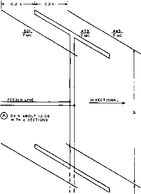 (B) GAIN ABOUT 15 DB WITH Э SECTIONS 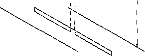 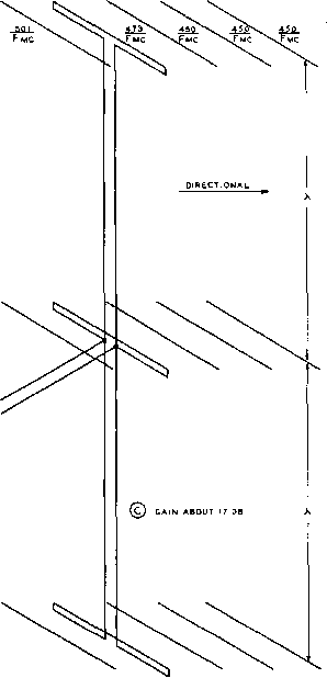 feeder line Figure 6 STACKED YAGI ARRAYS /* Is possible to attain a relatively large amount of gain over a limited bandwidth with stacked yagi arrays. The two-section array at (A) will give a gain of about 12 db, while adding a third sect/on will bring the gain up to about 15 db. Adding two additional parasitic directors fo each section, as at (C) will bring the gain up to about 17 db. higher where the additional section of tuhing may be supported below the main radiator element without undue difficulty. The yoke-match is more satisfactory mechanically on the 28- Mc. and 14-Mc. bands since it is only necessary to suspend a wire below the driven element proper. The wire may be spaced below the self-supporting element by means of several Rradiatiqw forDi =  FOLDED-ELEMENT MATCH i, FORDi=i YOKE MATCH  RE SIZE 3-WtRE MATCH  © 5-WIRE MATCH 
T2WIRE rad. R feed = 9 Rrad. i££iD: approx. 25 rad. Figure 7 DATA FOR FOLDED-ELEMENT MATCHING SYSTEMS In all normal applications of the data given the main element as shovrn is the driven e/emenf of a multi-element parasitic array. Directors and reflectors have not been shown for the sake of clarity. small Strips of polystyrene which have been drilled for both the main element and the small wire and threaded on the main element. The Folded-Element Match Calculations The calculation of the operating conditions of the fol ded-element matching system and the yoke match, as shown in figures 7A and 7B is relatively simple. A selected group of operating, conditions has been shown on the drawing of figure 7. In applying the system it is only necessary to multiply the ratio of feed to radiation resistance (given in the figures to the right of the suggested operating dimensions in figure 7) by the radiation resistance of the antenna system to obtain the impedance of the cable to be used in feeding the array. Approximate values of radiation resistance for a number of commonly used parasitic-elenKnt arrays are given in figure 5. As an example, suppose a 3-element array with 0.15D-0.15R spacing between elements is to be fed by means of a 465-ohm line constructed of no. 12 wire spaced 2 inches. The approximate radiation resistance of such an antetma array will be 20 ohms. Hence we need a ratio of impedance step up of 23 to obtain a match between the characteristic impedance of the transmission line and the radiation resistance of the driven element of the antenna array. Inspection of the ratios given in figure 7 shows that the fourth set of dimensions given under figure 7В will give a 24-to-l step up, which is sufficiently close. So it is merely necessary to use a 1-inch diameter driven element with a no. 8 wire spaced on 1 inch centers (Уг inch below the outside wall of the 1-inch tubing) below the 1-inch element. The no. 8 wire is broken and a 2-inch insulator placed in the center. The feed line then carries from this insulator down to the transmitter. The center insulator should be supported rigidly from the 1-inch tube so that the spacing between the piece of tubing and the no. 8 wire will be accurately maintained. 1 ... 46 47 48 49 50 51 52 ... 80 |
|||||||||||||||||||||||||||||||||||||||||||||||||||||||||||||||||||||||||||||||||||||||||||||||||||||||||||||||||||||||||||||||||||||||||||||||||||||||||||||||||||||||||||||||||||||||||||||||||||||||||||||||||||||||||||||||||||||||||||||||||||||||||||||||||||||||||||||||||||||||||||||||||||||||||||||||||||||||||||||||||||||||||||||||||||||||||||||||||||||||||||||||||||||||||||
|
© 2026 AutoElektrix.ru
Частичное копирование материалов разрешено при условии активной ссылки |