 |
 |
 |
| Главная Журналы Популярное Audi - почему их так назвали? Как появилась марка Bmw? Откуда появился Lexus? Достижения и устремления Mercedes-Benz Первые модели Chevrolet Электромобиль Nissan Leaf |
Главная » Журналы » Simple coaxial reflectometer 1 ... 47 48 49 50 51 52 53 ... 80 0 DELTA MATCH Figure 8 AVERAGE DIMENSIONS FOR THE DELTA AND T MATCH (E) *T MATCH  DIMENSIONS SHOWN GIVE APPROX. MATCH TO 900Л AIRSPACeO LINE  □i 3Dz In many cases it will be desired to use the folded-element or yoke matching system with different sizes of conductors or different spacings than those shown in figure 7. Note, then, that the impedance transformation ratio of these types of matching systems is dependent both upon the ratio of conductor diameters and upon their spacing. The following equation has been given by Roberts (UCA Review, June, 1947) for the determination of the impedance transformation when using different diameters in the two sections of a folded element: Transformation ratio = In this equation Zj is the characteristic impedance of a line made up of the smaller of the two conductor diameters spaced the center-to-center distance of the two conductors in the anteima, and Z, is the characteristic impedance of a line made up of two conductors the size of the larger of the two. This assumes that the feed line will be connected in series with the smaller of the two conductors so that an impedance step up of greater than four will be obtained. If an impedance step up of less than four is desired, the feed line is connected in series with the larger of the two conductors and Z, in the above equation becomes the impedance of a hypothetical line made up of the larger of the two conductors and Z, is made up of the smaller. The folded v-h-f unipole is an example where the transmission line is connected in series with the larger of the two conductors. The conventional 3-wire match to give an impedance multiplication of 9 and the 5-wire match to give a ratio of approximately 25 are shown in figures 7C and 7D. The 4-wire match, not shown, will give an impedance transformation ratio of approximately 16. The Delta Match and T-Mafch The Delta match and the T-match are shown in figure 8. The delta match has been largely superseded by the newer T-match, however both these systems can be adjusted to give a low value of SWR on 50 to 600-ohm balanced transmission lines. In the case of the systems shown it will be necessary to make adjustments in the tapping distance along the driven radiator until minimum standing waves on the antenna transmission line are obtained. Since it is sometimes impracticable to eliminate completely the standing waves from the anteima transmission line when using these matching systems, it is common practice to cut the feed line, after standing waves have been reduced to a minimum, to a length which will give satisfactory loading of the transmitter over the desired frequency range of operation. The inherent reactance of the T-match is tuned out by the use of two identical resonating capacitors in series with each leg of the T-rod. These capacitors should each have a maximum capacity of 8 tfd. per meter of wavelength. Thus for 20 meters, each cacitor should have a maximum capacity of at least 160 ppiA. For power up to a kilowatt, 1000 volt spacing of the capacitors is adequate.  (a) direct feed with coaxial cable COAXIAL CABLE  (g) QUARTER-WAVE TRANSFORMER FEED ©TRANSFORMER MATCHING SYSTEM i MC - 4 TURNS 2 DiA., 2 LONS ANT. TAPPED I TURN EACH SIDE 14 MC.-S TURNS 2DIA., 2 LONG ANT TAPPED 2 TURNS EACH SIDE Figure 9 ALTERNATE FEED METHODS WHERE THE DRIVEN ELEMENT MAY BE BROKEN IN THE CENTER ©ROTARY LINK COUPLING 1 TURN LINKS ARE PARALLEL С IS 200JJUFD VARIABLE 4&0-вООЛ. LINE These capacitors should be tuned for minimum SWR on the transmission line. The adjustment of these capacitors should be made at the same time the correct setting of the T-match tods is made as the two adjustments tend to be interlocking. The use of the standing wave meter (described in Test Equipment chapter) is recommended for making these adjustments to the T-match. Feed Systems Using a Driven Element with Center Feed Four methods of exciting the driven element of a parasitic array are shown in figure 9. The system shown at (A) has proven to be quite satisfactory in the case of an antenna-reflector two-element array or in the case of a three-element array with 0.2 to 0.25 wavelength spacing between the elements of the antenna system. The feed-point impedance of the center of the driven element is close enough to the characteristic impedance of the 52-ohro coaxial cable so that the standing-wave ratio on the 52-ohm coaxial cable is less than 2-to-l. (B) shows an arrangement for feeding an array with a broken driven element from an open-wire line with the aid of a quarter-wave matching transformer. With 465-ohm line from the transmitter to the antenna this system will give a close match to a 12-ohm impedance at the center of the driven element. (C) shows an arrangement which uses an untuned transformer with lumped inductance for matching the transmission line to the center impedance of the driven element. Rotary Link In many cases it is desirable to Coupling be able to allow the antenna ar- ray to rotate continuously without regard to snarling of the feed line. If this is to be done some sort of slip rings or rotary joint must be made in the feed line. One relatively simple method of allowing unrestrained rotation of .the antenna is to use the method of rotary link coupling shown in figure 9D. The two cou- HANDBOOK The Gamma Match 503 S2-0HM COAX CABLE L Ч - tOleL- Figure 10 THE GAMMA MATCHING SYSTEM See text for details of resonating capacitor FLAT LINE SWR = 1.0 RESONANT SECTION TO TRANSMITTER MATCHINS STUB Figure 11 IMPEDANCE MATCHING WITH A CLOSED STUB ON A TWO WIRE TRANSMISSION LINE pling rings are 10 inches in diameter and are usually constructed of J4-inch copper tubing supported one from the rotating structure and one from the Qxed structure by means of standoff insulators. The capacitor С in figure 9D is adjusted, after the antenna has been tuned, for minimum standing-wave ratio on the antenna transmission line. The dimensions shown will allow operation with either 14-Mc. or 28-Mc. elements, with appropriate adjustment of the capacitor C. The rings must of course be parallel and must lie in a plane normal to the axis of rotation of the rotating structure. The Gamma Match The use of coaxial cable to feed the driven element of a yagi array is becoming increasingly popular. One reason for this increased popularity lies in the fact that the TVI-reduction problem is simplified when coaxial feed line is used from the transmitter to the antenna system. Radiation from the feed line is minimized when coaxial cable is used, since the outer conductor of the line may be grounded at several points throughout its length and since the intense field is entirely confined within the outer conductor of the coaxial cable. Other advantages of coaxial cable as the anteima feed line lie in the fact that coaxial cable may be run within the structure of a building without danger, or the cable may be run underground without disturbing its operation. Also, trans-mitting-type low-pass filters for 52 ohm impedance are more widely available and are less expensive than equivalent filters for two-wire line. The gamma-match is illustrated in figtjre 10, and may be looked upon as one-half of a T-match. One resonating capacitor is used, placed in series with the gamma rod. The capacitor should have a capacity of 7 (ifitd. per meter of wavelength. For 15-meter operation the capacitor should have a maximum capacity of 105 [jfifd. The length of the gamma rod determines the impedance transformation between the transmission line and the driven element of the array, and the gamma capacitor tunes out the inductance of the gamma rod. By adjustment of the length of the gamma rod, and the setting of the gamma capacitor, the SWR on the coaxial line may be brought to a very low value at the chosen operating frequency. The use of an Antennascope, described in the Test Equipment chapter is recommended for precise adjustment of the gamma match. The Matching Stub If an open-wire line is used to feed a low impedance radiator, a section of the transmission line may be employed as a matching stub as shown in figure 11. The matching stub can transform any complex impedance to the characteristic impedance of the transmission line. While it is possible to obtain a perfect match and good performance with either an open stub or a shorted one by observing appropriate dimensions, a shorted stub is much more readily adjusted. Therefore, the following discussion will be confined to the problem of using a closed stub to match a low impedance load to a high impedance transmission line. If the transmission line is so elevated that adjustment of a fundamental shorted stub cannot be accomplished easily from the ground, then the stub length may be increased by exactly one or two electrical half wavelengths, without appreciably affecting its operation. While the correct position of the shorting bar and the point of attachment of the stub to the line can be determined entirely by experimental methods, the fact that the two adjustments are interdependent or interlocking makes such a cut-and-try procedure a tedious one. Much time can be saved by determining the approximate adjustments required by reference to a chart such as figure 12 and using them as a starter. Usually only a slight touching up will produce a perfect match and flat line. In order to Utilize figure 12, it is first necessary to locate accurately a voltage node or current node on the line in the vicinity that i t/зя -I <
SWR Figure 12 SHORTED STUB LENGTH AND POSITION CHART From the startding wave ratio and current or voltage null position it is possible to determine the theoretically correct length and position of a shorted stub. In actual practice a slight discrepancy usufflly will be found between the theoretical and fhe experimentally optimized dimensions; therefore It may be necessary to touch up the dimensions after using the above data as a starting point. has been decided upon for the stub, and also to determine the SWR. Stub adjustment becomes more critical as the SWR increases, and under conditions of high SWR the current and voltage nulls are more shaфIy defined than the current and voltage maxima, or loops. Therefore, it is best to locate either a current null or voltage null, depending upon whether a current indicating device or a voltage indicating device is used to check the standing wave pattern. The SWR is determined by means of a directional coupler, or by noting the ratio of Ema to E in or Imai to Iin as read on an indicating device. It is assumed that the characteristic impedance of the section of line used as a stub is the same as that of the transmission line proper. It is preferable to have the stub section identical to the line physically as well as electrically. 25-5 Unidirectional Driven Arrays Three types of unidirectional driven arrays are illustrated in figure 13- The array shown in figure 13A is an end-fire system which may 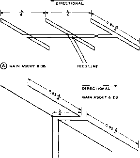 feed line 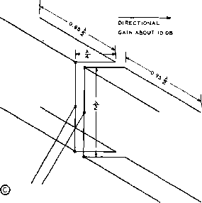 feed LINE Figure 13 UNIDIRECTIONAL ALL-DRIVEN ARRAYS A unidirectional all-driven end-fire array Is shown at (A). (B) shows an array with two half waves in phase with driven reflectors, A Lazy-H array with driven reflectors is shown ot (C). Note that the directivity is through the elements with the greatest total feed-line length in arrays such as shown at (B) and (C). be used in place of a parasitic array of similar dimensions when greater frequency coverage than is available with the yagi type is desired. Figure 13B is a combination end-fire and со- linear system which will give approximately the same gain as the system of figure 13A, but which requires less boom length and greater total element length. Figure 13C illustrates the familiar lazy-H with driven reflectors (or directors, depending upon the point of view) in a combination which will show wide bandwidth with a considerable amount of forward gain and good front-to-back ratio over the entire frequency coverage. Unidirectional Stacked Three practicable Broadside Arrays types of unidirectional stacked broadside arrays are shown in figure 14. The first type, shown at figure 14A, is the simple lazy H type of antenna with parasitic reflectors for each element. (B) shows a simpler antenna array with a pair of folded dipoles spaced one-half wave vertically, operating with reflectors. In figure 14C is shown a more complex array with six half waves and six reflectors which will give a very worthwhile amount of gain. In all three of the antenna arrays shown the spacing between the driven elements and the reflectors has been shown as one-quarter wavelength. This has been done to eliminate the requirement for tuning of the reflector, as a result of the fact that a half-wave element spaced exactly one-quarter wave from a driven element will make a unidirectional array when both elements are the same length. Using this procedure will give a gain of 3 db with the reflectors over the gain without the reflectors, with only a moderate decrease in the radiation resistance of the driven element. Actually, the radiation resistance of a half-wave dipole goes down from 73 ohms to 60 ohms when an identical half-wave element is placed one-quarter wave behind it. A very slight increase in gain for the entire array (about 1 db) m be obtained at the expense of lowered radiation resistance, the necessity for tuning the reflectors, and decreased bandwidth by placing the reflectors 0.15 wavelength behind the driven elements and making them somewhat longer than the driven elements. The radiation resistance of each element will drop approximately to one-half the value obtained with untuned half-wave reflectors spaced one-qu£u:ter wave behind the driven elements. Antenna arrays of the type shown in figure 14 require the use of some sort of lattice work for the supporting structure since the arrays occupy appreciable distance in space in all three planes. Feed Methods The requirements for the feed systems for antenna arrays of the type shown in figure 14 are less critical than diose for the close-spaced parasitic arrays shown in the previous section. This is a natural result of the fact that a larger number of the radiating elements are directly fed with energy, and of the fact that the effective radiation resistance of each of the driven elements of the array is much higher than the feed-point resistance of a parasitic array. As a consequence of this fact, arrays of the type shown in figure 14 can be expected to cover a somewhat greater frequency band for a specified value of standing-wave ratio than the parasitic type of array. In most cases a simple open-wire line may be coupled to the feed point of the array without any matching system. The standing-wave ratio with such a system of feed will often be less than 2-to-l. However, if a more accurate match between the antenna transmission line and the array is desired a conventional queur-ter-wave stub, or a quarter-wave matching transformer of propriate impedance, may be used to obtain a low standing-wave ratio. 25-6 Bi-Direcrional Rotatable Arrays The bi-directional type of array is sometimes used on the 28-Mc. and 50-Mc. bands where signals are likely to be coming from only one general direction at a time. Hence the sacrifice of discrimination against signals arriving from the opposite direction is likely to be of little disadvantage. Figure 15 shows two general types of bi-directional eurrays. The flattop beam, which has been described in detail earlier, is well adapted to installation atop a rotating structure. When self-supporting elements are used in the flat-top beam the problem of losses due to insulators at the ends of the elements is somewhat reduced. With a single-section flat-top beam a gain of approximately 4 db can be expected, and with two sections a gain of approximately 6 db can be obtained. Another type of bi-directional array which has seen less use than it deserves is shown in figure 15B. This type of antenna system has a relatively broad azimuth or horizontal beam, being capable of receiving signals with little diminution in strength over approximately 40°, but it has a quite shaip elevation pattern since substantially all radiation is concentrated at the lower angles of radiation if more than a total of four elements Is used in the antenna system. Figure 15B gives the approximate gain over a half-wave dipole at the height of the center of the array which can be expected. Also shown in this figure is a type of rotating mast structure which is well suited to rotation of this type of array. 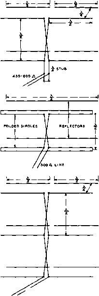 ® LAZY H WITH REFLECTOR CAIN APPROX. 9 DB BROADSIDE HALF-WAVES WITH REFLECTORS GAIN APPROX. 7 OB TWO OVER TWO OVER TWO WITH REFLECTORS GAIN APPROX. 1i.S DB Figure 14 BROADSIDE ARRAYS WITH PARASITIC REFLECTORS The apparent gain of the or. rays illustrated will be great er than the values given due to concentration af the radi ated signal at the lower e/e-vattan angles. tbSi. LINE If six or more elements are used in the type of array shown in figure 15B no matching section will be required between the antenna transmission line and the feed point of the antenna. When only four elements are used the antenna is the familiar lazy H and a quarter-wave stub should be used for feeding from the antenna transmission line to the feed point of the antenna system. If desired, and if mechanical considerations permit, the gain of the arrays shown in figure 15B may be increased by 3 db by placing a half-wave reflector behind each of the elements at a spacing of one-quarter wave. The array then becomes essentially the same as that shown in figure 14C and the same con-siderarions in regard to reflector spacing aod tuning will apply. However, the factor that a bi-directional array need be rotated through an angle of less than 180** should be considered in this connection. 25-7 Construction of Rotatable Arrays A considerable amount of ingenuity may be exercised in the construction of the supporting structure for a rotatable array. Every person has his own ideas as to the best method of construction. Often the most practicable method of construction will be dictared by the  OPEN-WIRE LINE FLAT-TOP BEAM FOR ROTATABLE ARRAY SAIN 4 TO a DB Figure 15 TWO GENERAL TYPES OF BI-DIRECTIONAL ARRAYS Averoge gain figures are given for both the flat-top beam type of array and for the broadside-colinear array with different numbers of elements. 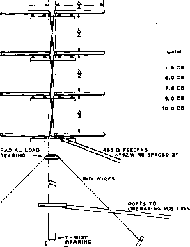 ® TWO OVER TWO OVER TVI/O* TYPE OF ARRAY TOTAL NUMBER DF ELEMENTS г availability of certain types of constructional materials. But in any event be sure that sound mechanical engineering principles are used in the design of the supporting structure. There are few things quite as discouraging as the picking up of pieces, repairing of the roof, etc., when a newly constructed rotary comes down in the first strong wind. If the principles of mechanical engineering are understood it is wise to calculate the loads and torques which will exist in the various members of the structure with the highest wind velocity which may be expected in the locality of the installation. If this is not possible it will usually be worth the time and effort to look up a friend who understands these principles. Radiating One thing more or less standard Elements about the construction of rotatable antenna arrays is the use of dural tubing for the self-supporting elements. Other materials may be used but an alloy known as 24ST has proven over a period of time to be quite satisfactory. Copper tubing is too heavy for a given strength, and steel tubing, unless copper plated, is likely to add an undesirably large loss resistance to the array. Also, steel tubing, even when plated, is not likely to withstand salt atmosphere such as encountered along the seashore for a satisfactory period of time. Do not use a soft aluminum alloy for the elements unless they will be quite short; 24ST is a hard alloy and is best although there are several other alloys ending in ST which will be found to be satisfactory. Do not use an alloy ending in SO or S in a position in the array where structural strength is important, since these letters designate a metal which has not been heat treated for strength and rigidity. However, these softer alloys, and aluminum electrical conduit, may be used for short radiating elements such as would be used for the 50-Mc. band or as interconnecting conductors in a stacked array. 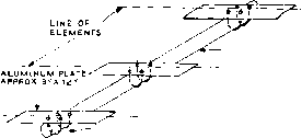 boom.made of sections ofsteel tv mast or of aluminum i rr igation Tubing -ELEMENT HELD TO PLATE WITH U-BOLTS, {zreq-d) OR MUFFLER CLAMPS. \SHIM joint WITH THIN strips of ALUMINUM i f NECESSARY. RADIATOR HOSE CLAMP 12 CENTER SECTION ADJUSTABLE s Ll T CENTER S ECTI ON TUBE ADJUSTABLE TIP 3* AT EACH END. tip TYPICAL ELEMENT Figure 16 3-ELEMENT PLUMBERS DELIGHT ANTENNA ARRAY All-metal configuration permits rugged, light assembly. Joints are made with U-bolts and metal plates for maximum rigidity. Plumbers Delight It is characteristic of Construction conventional type of multi-element parasitic array such as discussed previously and outlined that the centers of all the elements are at zero r-f potential with respect to ground. It is therefore possible to use a metallic structure without insulators for supporting the various elements of the array. A typical three element array of this type is shown in figure l6. In this particular array, U-bolts and metal plates have been employed to fasten the elements to the boom. The elements are made of telescoping sections of aluminum tubing. The tips of the inner sectionsof tubingare split, and a tubing clamp is slipped over the joint, as shown in the drawing. Before assembly of the joint, the mating pieces of aluminum are given a thin coat of Penetrox-A compound. (This anti-oxidizing paste is manufactured by Burndy Co., Norwalk, Conn, and is distributed by the General Electric Supply Co.) When the tubes are telesaoped and the clamp is tightened, an air-tight seal is produced, reducing corrosion to a minimum. The boom of the parasitic array may be made from two or three sections of steel TV mast, or it may be made of a single section of aluminum irrigation pipe. This pipe is made by Reynolds Aluminum Co., and others, and may often be purchased via the Sears, Roebuck Co. mail-order department. Three inch pipe may be LINE OF ELEMENT u-BOLT LINE OF BOOM 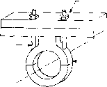 ELEMENT CLAMP 2 pieces BOOM CLAMP 2 PIECES OXEN-YOKE CLAMP ladder 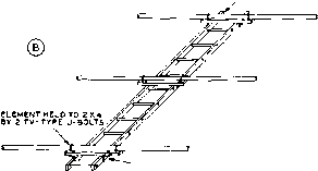 -2X4 BOLTED TO LADDER BY 2 PIECES OF ANGLE IRON STOCK Figure 17 (A) OXEN-YOKE CLAMP IS DESIGNED FOR ALL METAL ASSEMBLY (B) ALTERNATIVE WOODEN SUPPORTING ARRANGEMENT A wooden ladder may be used to support a 10 or 15 meter array. used for the 10 and 15 meter antennas, and the huskier four inch pipe should be used for a 20 meter beam. Automobile muffler clamps can often be used to affix the elements to the support plates. Larger clamps of this type will fasten the plates to the boom. In most cases, the muffler clamps are untreated, and they should be given one or two coats of rust-proof paint to protect them from inclemenr weather. All .bolts, nuts, and washers used in the assembly of the array should be of the plated variety to reduce corrosion and rust. An alternative assembly is to employ the *Oxen Yoke type of clamps, shown in figure 17- These light-weight aluminum fittings are obtainable from the Continental Electronics and Sound Co., Dayton, 27, Ohio, and are available in a wide range of sizes. If it is desired to use a split driven element for a balanced feed system, it is necessary to insulate the element from the supporting structure of the antenna. The element should be severed at the center, and the two halves HANDBOOK Tuning line Array 509 driven onto a wooden dowel, as shown in figure 17B. The element may then be mounted upon an aluminum support plate by means of four ceramic insulators. Metal based insulators, such as the Johnson 135-67 are recommended, since the all-ceramic types may break at the mounting holes when the array is subjected to heavy winds. 25-8 Tuning the Array Although satisfactory results may be obtained by pre-cutting the antenna array to the dimensions given earlier in this chapter, the occasion might arise when it is desired to make a check on the operation of the antenna before calling the job complete. The process of tuning an array may fairly satisfactorily be divided into two more or less distinct steps: the actual tuning of the Euray for best front-to-back ratio or for maximum forward gain, and the project of obtaining the best possible impedance match between the antenna transmission line and the feed point of the array. Tuning the The actual tuning of the array Array Proper for best front-to-back ratio or maximum forward gain may best be accomplished with the aid of a low-power transmitter feeding a dipole antenna (polarized the same as the array being tuned) at least four or five wavelengths away from the antenna being tuned and located at the same elevation as that of the antenna under test. A calibrated field-strength meter of the remote-indicating type is then coupled to the feed point of the antenna array being tuned. The transmissions from the portable transmitter should be made as short as possible and the call sign of the station making the test should be transmitted at least every ten minutes. It is, of course, possible to tune an array with the receiver connected to it and with a station a mile or two away making transmissions on your request. But this method is more cumbersome and is not likely to give complete satisfaction. It is also possible to carry out the tuning process with the transmitter connected to the array and with the field-strength meter connected to the remote dipole antenna. In this event the indicating instrument of the remote-indicating fie Id-strength meter should be visible from the position where the elements are being tuned. However, when the array is being tuned with the transmitter connected to it there is always the problem of making continual adjustments to the transmitter so that a constant amount of power will be fed to the array under test. Also, if you use this system, use very low power (5 or 10 watts of power is usually sufficient) and make sure that the antenna transmission line is effectively grounded as far as d-c plate voltage is concerned. The use of the method described in the previous paragreh of course eliminates these problems. One satisfactory method for tuning the array proper, assuming thait it is a system with several parasitic elements, is to set the directors to the dimensions given in figure 5 and then to adjust the reflector for maximum forward signal. Then the first director should be varied in length until maximum forward signal is obtained, and so on if additional directors are used. Then the array may be reversed in direction and the reflector adjusted for best front-to-back ratio. Subsequent small adjustments may then be made in both the directors and the reflector for best forward signal with a reasonable ratio of front-to-back signal. The adjustments in the directors and the reflector will be found to be interdependent to a certain degree, but if small adjustments are made after the preliminary tuning process a satisfactory set of adjustments for maximum performance will be obtained. It is usually best to make the end sections of the elements smaller in diameter so that they will slip inside the larger tubing sections. The smaller sliding sections may be clamped inside the larger main sections. In making the adjustments described, it is best to have the rectifying element of the remote-indicating field-strength meter directly at the feed point of the array, with a resistor at the feed point of the estimated value of feed-point impedance for the array. Matching to the The problem of matching the Antenna Trans- impedance of the antenna mission Line transmission line to the array is much simplified if the pro- 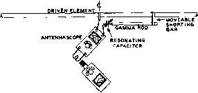 SRIDDIP METER Figure 18 ADJUSTMENT OF GAMMA MATCH BY USE OF ANTENNASCOPE AND GRID-DJP METER MAST UP TO FULL HEIGHT THE STATiONAIiY PIPE CAN BE SECURELY SftACED TO ftOOF PARTS BY BLOCKS ANO U-BOLTS  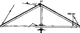 IMPORTANT NOTE BE SURE THAT THE PIPES FIT WITHOUT BINDING AS THERE IS SOME VARIATION IN DIAMETERS OF THE SIZES USED. I I I I fftON PIPE LENGTH TO FIT AS PER OTHER DRAWINGS TWO 3/8* OR 1/2 MACHINE . SCREWS AftOUr t/2- LONG THROUGH BEAftiNS PCECE ANO TAPPED INT101 PIPE. I I I I II I - -ABOUT 2* OF t 1/4 PIPE. THIS iS THE BEARING THAT CARRIES THE LOAD. к LONG THREAD* SO THAT 1 1/4 PIPE EXTENOSABOUT 1/2 ABOVE FLANGE WEATHER-TIGHT GALVANIZED IRON RAIN SHIELD 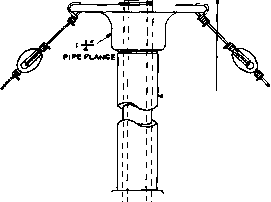 г OF THE Guy WIRES SHOWN LENGTH DEPENDS ~1C HEIGHT PLANK OVER SEVERAL JOISTS TO DISTRIBUTE THE WEIGHT AUTO STEERING WHEEL ,д RGBU OR SMALLER \ ANTENNA FEEDER MAY BE RUN THRU PIPE IPIPE LOWERS TO INSTALL ANTENNAOR ADJUST PITCHED ROOF INSTALLATION 1 PIPE FUANGE -1 1/4 IRON PIPE LENGTH TO FIT AS PER OTHER DRAWINGS. 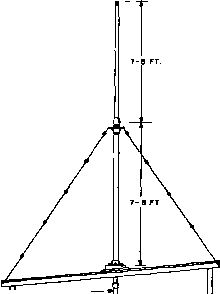 о < со I I REMOVABLE EXTENSION MAYBE USED TO LOWER THE WHEEL. I FLAT Oft SHED ROOF INSTALLATION > о 1 ... 47 48 49 50 51 52 53 ... 80 |
|||||||||||||||||||||||||||||||||||||||||||||||||||||||||||||||||||||||||||||||||||||||||||||||||||||||||||||||||||||||||||||||||||||||||||||||||||||||||||||||||||||||||||||||||||||||||||||||||||||||||||||||||||||||||||||||||||||||||||||||||||||||||||||||||||||||||||||||||||||||||||||||||||||||||||||||||||||||||||||||||||||||||||||||||||
|
© 2026 AutoElektrix.ru
Частичное копирование материалов разрешено при условии активной ссылки |