 |
 |
 |
| Главная Журналы Популярное Audi - почему их так назвали? Как появилась марка Bmw? Откуда появился Lexus? Достижения и устремления Mercedes-Benz Первые модели Chevrolet Электромобиль Nissan Leaf |
Главная » Журналы » Simple coaxial reflectometer 1 ... 48 49 50 51 52 53 54 ... 80 HANDBOOK Tuning the Array 511 cess of tuning the array is made a substantially separate process as just described. After the tuning operation is complete, the resonant frequency of the driven element of the antenna should be checked, directly at the center of the driven element if practicable, with a grid-dip meter. It is important that the resonant frequency of the antenna be at the center of the frequency band to be covered. If the resonant frequency is found to be much different from the desired frequency, the length of the driven element of the array should be altered until this condition exists. A relatively small change in the length of the driven element will have only a second order effect on the tuning of the parasitic elements of the array. Hence, a moderate change in the length of the driven element may be made without repeating the tuning process for the parasitic elements. When the resonant frequency of the antenna system is correct, the antenna transmission line, with impedance-matching device or network between the line and antenna feed point, is then attached to the array and coupled to a low-power exciter unit or transmitter. Then, preferably, a standing-wave meter is connected in series with the antenna transmission line at a point relatively much more close to the transmitter than to the antenna. However, for best indication there should be 10 to 15 feet of line between the transmitter and the standing-wave meter. If a standing-wave meter is not available the standing-wave ratio may be checked approximately by means of a neon lamp or a short fluorescent tube if twin transmission line is being used, or it may be checked with a thermomilliammeter and a loop, a neon lamp, or an r-f ammeter and a pair of clips spaced a fixed distance for clipping onto one wire of a two-wire open line. If the standing-wave ratio is below 1.5 to 1 it is satisfactory to leave the installation as it is. If the ratio is greater than this range it will be best when twin line or coaxial line is being used, and advisable with open-wire line, to attempt to decrease the s.w.r. It must be remembered that no adjustments made at the transmitter end of the transmission line will alter the SWR on the line. All adjustments to better the SWR must be made at the antenna endof the line and to the device which performs the impedance transformation necessary to match the characteristic impedance of the antetma to that of the transmission line. Before any adjustments to the matching system are made, the resonant frequency of the driven element must be ascertained, as explained previously. If all adjustments to correct impedance mismatch are made at this frequency, the problem of reactance termination of the transmission line is eliminated, greatly simplifying the problem. The following steps should be taken to adjust the impedance transformation: 1. The оифШ impedance of the matching device should be measured. An Antenna-scope and a grid-dip oscillator are required for this step. The Antennascope is connected to the output terminals of the matching device. If the driven element is a folded dipole, the Antennascope coruiects directly to the split section of the dipole. If a gamma match or T-match are used, the Antennascope connects to the transmission-line end of the device. If a Q-section is used, the Antennascope connects to the bottom end of the section. The grid-dip oscillator is coupled to the input terminals of the Antennascope as shown in figure 18. 2. The grid-dip oscillator is tuned to the resonant frequency of the antenna, which Figure 19 ALL-PIPE ROTATING MAST STRUCTURE FOR ROOF INSTALLATION Ал installation suitable for о building with о pitched roof is shown ot (A), At (B) is shown a similar installation for a flat or shed roof. The arrangement os shown is strong enough to support a lightweight 3-element 28-Mc. array and a light 3-element 50-Mc. array above the 28-Mc. array on the end of о 4-foot length of Vt-inch pipe. The lengths of pipe shown were chosen so thot when the system is in the lowered position one can stand on a household ladder and put the beam in position atop the rotating pipe. The lengths moy safely be revised upward somewhat if the array is of a particularly lightweight design with low wind resistance. Just before the mast is installed it is a good ideo to give the rotating pipe a good smearing of cup grease or waterproof pump grease. To get the lip of the top of the stationary section of 7 lit-inch pipe to project above the flange plate, it will be necessary to have о plumbing shop cut о slightly deeper thread inside the flange plote, as well os cutting on unusually long thread on the end of the I /4-/nch p/pe. It is re/atlve/y easy fo waterproof this assembly through the roof since the J /4-inch pipe is stationary at oil times. Be sure to use pipe compound on oil the joints ond then reolly tighten these joints with a pair of pipe wrenches. has been determined previously, and the Antennascope control is turned for a null reading on the meter of the Antennascope. The impedance presented to the Antennascope by the matching device may be read directly on the calibrated dial of the Antennascope. 3. Adjustments should be made to the matching device to present the desired impedance transformation to the Antennascope. If a folded dipole is used as the driven element, the transformation ratio of the dipole must be varied as explained previously in this chter to provide a more exact match. If a T-match or gamma match system is used, the length of the matching rod may be changed to effect a proper match. If the Antennascope ohmic reading is lower than the desired reading, the length of the matching rod should be increased. If the Antennascope reading is higher than the desired reading, the length of the matching tod should be decreased. After each change in length of the matching rod, the series capacitor io the matching system should be re-resonated for best null on the meter of the Antennascope. Roistng and A practical problem always pres-Lowering eot when tuning up and matching the Array an array is the physical location of the structure. If the array is atop the mast it is inaccessible for adjustment, and if it is located on stepladders where it can be adjusted easily it cannot be rotated. One encouraging factor in this situation is the fact that experience has shown that if the array is placed 8 or 10 feet above ground on some step-ladders for the preliminary tuning process, the raising of the system to its full height will not produce a serious change io the adjustments. So it is usually possible to make preliminary adjustments with the system located slightly greater than head height above ground, and then to raise the antenna to a position where it may be rotated for final adjustments. If the position of the sliding sections as determined near the ground is marked so that the adjustments will not be lost, the array may be raised to rotatable height and the fastening clamps left loose enough so that the elements may be slid in by means of a long bamboo pole. After a series of trials a satisfactory set of lengths can be obtained. But the end results usually come so close to the figures given in figure 5 that a subsequent array is usually cut to the dimensions given and installed as-is. The matching process does not require rotation, but it does require that the antenna proper be located at as nearly its normal oper-  Figure 20 HEAVY DUTY ROTATOR SUITABLE FOR AMATEUR BEAMS The new Cornell-DubHier type HAM-I rotor has extra heavy motar and gearing system to withstand weight and Inertia of anateur array under the buffeting of heavy winds. Steel spur gears and rotor lock prevent pin-wheeling of antenna. HANDBOOK Antenna Control Systems 513 CONTROL BOX ANTENNA ROTATOR 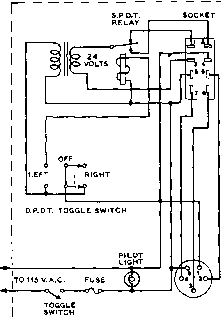 SOCKET e-CONTACT JONES PLUGS i SOCKETS ROTARY BEAM CONTROL  PLUG 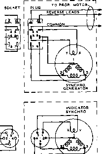 PLUG r~lr I DIRECTION INDICATOR Figure 21 SCHEMATIC OF A COMPLETE ANTENKA CONTROL SYSTEM ating position as possible. However, on a particular installation the positions of the current minimuras on the transmission line near the transmitter may be checked with the array in the air, and then the array may be lowered to ascertain whether or not the positions of these points have moved. If they have not, and in most cases if the feeder line is strung out back and forth well above ground as the antenna is lowered they will not change, the positions of the last few toward the antenna itself may be determined. Then the calculation of the matching quarter-wave section may be made, the section installed, the standing-wave ratio again checked, and the antenna re-installed in its final location. 25-9 Antenna Rotation Systems Structures for the rotation of antenna arrays may be divided into two general classes: the rotating mast and the rotating platform. The rotating mast is especially suitable where the transmitting equipment is installed in the garage or some structure away from the main house. Such an installation is shown in figure 19. A very satisfactory rotation mechanism is obtained by the use of a large steering wheel located on the bottom pipe of the rotating mast, with the thrust bearing for the structure located above the roof. If the rotating mast is located a distance from the operating position, a system of pulleys and drive rope may be used to turn the antenna, or a slow speed electric motor may be employed. The rotating platform system is best if a tower or telephone pole is to be used for antenna support. A number of excellent rotating platform devices are available on the market for varying prices. The larger and more expensive rotating devices are suitable for the rota-of a rather sizeable array for the 14-Mc. band while the smaller structures, such as those designed for rotating a TV antenna are designed for less load and should be used only with a 28-Mc. or 50-Mc. array. Most common practice is to install the rotating device atop a platform built at the top of a telephone pole or on the top of a lattice mast of sizeable cross section so that the mast will be self-supporting and capable of withstanding the torque imposed upon it by the rotating platform. A heavy duty TV rotator may be employed for rotation of 6 and 10-meter arrays. Fifteen and twenty meter arrays should use rotators designed for amateur use such as the Comell-Dubilier HAM-1 unit shown in figure 20. 514 Rotary Beams 25-10 Indication of Direction The most satisfactory method for indicating the direction of transmission of a rotatable array is that which uses Selsyns or synchros for the transmission of the data from the rotating structure to the indicating pointer at the operating position. A number of synchros and Selsyns of various types are available on the surplus market. Some of them are designed for operation on 115 volts at 60 cycles, some are designed for operation on 60 cycles but at a lowered voltage, and some are designed for operation from 400-cycle or 800-cycle energy. This latter type of high-frequency synchro is the most generally available type, and the high-frequency units are smaller and lighter than the 60-cycle units. Since the indicating synchro must deliver an almost negligible amount of power to the pointer which it drives, the high-frequency types will operate quite satisfactorily from 60-cycle power if the voltage on them is reduced to somewhere between 6.3 and 20 volts. In the case of many of the units available, a connection sheet is provided along with a recoimnendation in regard to the operating voltage when they are run on 60 cycles. In any event the operating voltage should be held as low as it may be and still give satisfactory transmission of data from the antenna to the operating position. Certainly it should not be necessary to run such a voltage on the units that they become overheated. A suitable Selsyn indicating system is shown in figure 21. Systems using a potentiometer capable of continuous rotation and a milliammeter, along with a battery or other source of direct current, may also be used for the indication of direction. A commercially-available potentiometer (Ohmite RB-2) may be used in conjunction with a 0-1 d-c milliammeter having a hand-calibrated scale for direction indication. 25-11 Three-Band Beams A popular form of beam antenna introduced during the past few years is the so-called three-band beam. An array of this type is designed to operate on three adjacent amateur bands, such as the ten, fifteen, and twenty meter group. The principle of operation of this form of antenna is to employ parallel tuned circuits placed at critical positions in the elements of the beam which serve to electrically connect and disconnect the outer sections of the elements as the frequency of excitation of the antenna is changed. A typical three-band element is shown in figure 22. At the lowest operating frequency, the tuned traps exert a minimum influence upon the element and it resonates at a frequency determined by the electrical length of the configuration, plus a slight degree of loading contributed by the traps. At some higher frequency (generally about 1.5 times the lowestoperatingfrequeacy) the outer set of traps are in a parallel resonant condition, placing a high impedance between the element and the tips beyond the traps. Thus, the element resonates at a frequency 1.5 times higher than that determined by the overall length of the element. As the frequency of operation is raised to approximately 2.0 times the lowest operating frequency, the inner set of traps become resonant, effectively disconnecting a larger portion of the element from the driven section. The length of the center section is resonant at the highest frequency of operation. The center section, plus the two adjacent inner sections are resonant at the intermediate frequency of operation, and the complete element is resonant at the lowest frequency of operation. The efficiency of such a system is determined by the accuracy of tuning of both the element sections and the isolating traps. In addition the combined dielectric losses of the traps affect the overall antenna efficiency. As with all multi-purpose devices, some compromise between operating convenience and efficiency must be made with antennas designed to operate over more than one narrow band of frequencies. It is a tribute to the designers of the better multi-band beams that they perform as well as they do, taking into account the theoretical difficulties that must be overcome. -RESONANT-* AT HISHEST rREOUEHCY - RESONANT -- AT- INTERMEDIATE FReQUENCT -RESONANT AT LOWESTFREOUENCY- Figure 22 TRAP-TYPE THREE BAND-ELEMENT Isolating traps permit dipole to be self-resonant at three widely different frequencies. Mobile Equipment Design and Instaliati Mobile operation is permitted on all amateur bands. Tremendous impetus to this phase of the hobby was given by the suitable design of compact mobile equipment. Complete mobile installations may be purchased as packaged units, or the whole mobile station may be home built, according to the whim of the operator. The problems involved in achieving a satisfactory two-way installation vary somewhat with the band, but many of the problems are common to all bands. For instance, ignition noise is more troublesome on 10 meters than on 75 meters, but on the other hand an efficient antenna system is much more easily accomplished on 10 meters than on 75 meters. Also, obtaining a worthwhile amount of transmitter output without excessive battery drain is a problem on all bands. 26-1 Mobile Reception When a broadcast receiver is in the car, the most practical receiving arrangement involves a converter feeding into the auto set. The advantages of good selectivity with good image rejection obtainable from a double conversion superheterodyne are achieved in most cases without excessive birdie troubles, a com- mon difficulty with a double conversion superheterodyne constructed as an integral receiver in one cabinet. However, it is important that the b-c receiver employ an r-f stage in order to provide adequate isolation between the converter and the high frequency oscillator in the b-c receiver. The r-f stage also is desirable from the standpoint of image rejection if the converter does not employ a tuned output circuit (tuned to the frequency of the auto set, ually about 1500 kc). A few of the late model auto receivers, even in the better makes, do not employ an r-f stage. The usual procedure is to obtain converter plate voltage from the auto receiver. Experience has shown that if the converter does not draw more than about 15 or at most 20 ma. total plate current no damage to the auto set or loss in performance will occur other than a slight reduction in vibrator life. The converter drain can be minimized by avoiding a voltage regulator tube on the converter h-f oscillator. On 10 meters and lower frequencies it is possible to design an oscillator with sufficient stability so that no voltage regulator is required in the converter. With some cars satisfactory 75-meter operation can be obtained without a noise clipper if resistor type sparli plugs (such as those made by Autolite) are employed. However, a noise clipper is helpful if not absolutely neces- 8690 sary, and it is recommended that a noise clipper be installed without confirming the necessity therefor. It has been found that quiet reception sometimes may be obtained on 75 meters simply by the use of resistor type plugs, but after a few thousand miles these plugs often become less effective and no longer do a fully adequate job. Also, a noise clipper insures against ignition noise from passing trucks and un-suppressed cars. On 10 meters a noise clipper is a must in any case. Modifying the There are certain things that Auto Receiver should be done to the auto set when it is to be used with a converter, and they might as well be done all at the same time, because dropping an auto receiver and getting into the chassis to work on it takes quite a little time. First, however, check the circuit of the auto receiver to see whether it is one of the few receivers which employ circuits which complicate connection of a noise clipper or a converter. If the receiver is yet to be purchased, it is well to investigate these points ahead of time. If the receiver uses a negative В resistor strip for bias (as evidenced by the cathode of the audio output stage being grounded), then the additional plate current drain of the converter will upset the bias voltages on the various stages and probably cause trouble. Because the converter is not on all the time, it is not practical simply to alter the resistance of the bias strip, and major modification of the receiver probably will be required. The best type of receiver for attachment of a converter and noise clipper uses an r-f stage; permeability tuning; single unit construction (except possibly for the speaker); push button tuning rather than a tuning motor; a high vacuum rectifier such as a 6X4 (rather than an 0Z4 or a synchronous rectifier); a 6SQ7 (or miniature or Loctal equivalent) with grounded cathode as second detector, first audio, and a.v.c; power supply negative grounded directly (no common bias strip); a PM speaker (to minimize battery drain); and an internal r-f gain control (indicating plenty of built-in reserve gain which may be called upon if necessary). Many current model auto radios have all of the foregoing features, and numerous models have most of them, something to keep in mind if the set is yet to be purchased. Noise Limiters A noise limiter either may be built into the set or purchased as a commercially manufactured unit for outboard connection via shielded wires. If the receiver employs a 6SQ7 (or Loctal or miniature equivalent) in a conventional circuit, it is a simple matter to build in a noise clipper by 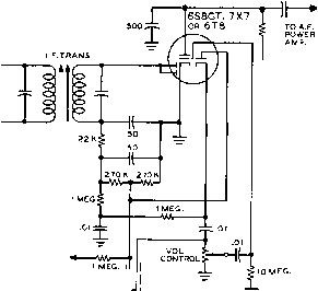 TO AVC BUSS SWITCH, SW = (IN-OUT Figure 1 SERIES-GATE NOISE LIMITER FOR AUTO RECEIVER Auto receivers using о 6SQ7, 7B6, 7X7, or 6AT6 as second detector and a.v.c. can be converted to the obove circuit with but few wiring changes. The circuit has the advantage of not requiring an additional tube socket for the limiter diode. substituting a 6S8 octal, 7X7 Loctal, or a 6Т8 9-pin miniature as shown in figure 1. When substituting a бТ8 for a 6AT6 or similar 7-pin miniature, the socket must be changed to a 9-pin miniature type. This requires reaming the socket hole slightly. If the receiver employs cathode bias on the 6SQ7 (or equivalent), and perhaps delayed a.v.c, the circuit usually can be changed to the grounded-cathode circuit of figure 1 without encountering trouble. Some receivers take the r-f excitation for the a-v-c diode from the plate of the i-f stage. In this case, leave the a.v.c. alone and ignore the a-v-c buss connection shown in figure 1 (eliminating the 1-megohm decoupling resistor). If the set uses a separate a-v-c diode which receives r-f excitation via a small capacitor connected to the detector diode, then simply change the circuit to correspond to figure 1. In case anyone might be considering the use of a crystal diode as a noise limiter in conjunction with the tube already in the set, it might be well to point out that crystal diodes perform quite poorly in series-gate noise clippers of the type shown. It will be observed that no tone control is shown. Multi-position tone controls tied in with the second detector circuit often permit excessive leak through. Hence it is recommended that the tone control components be completely removed unless they are confined to the grid of the a-f оифШ stage. If removed, the highs can be attenuated any desired amount by connecting a mica capacitor from plate to screen on the output stage. Ordinarily from .005 to .01 fifd. will provide a good compromise between fidelity and reduction of background hiss on weak signals. Usually the switch SW will have to be mounted some distance from the noise limiter components. If the leads to the switch are over afroximately lYz inches long, a piece of shield braid should be slipped over them and grounded. The same applies to the hot leads to the volume control if not already shielded. Closing the switch disables the limiter. This may be desirable for reducing distortion on broadcast reception or when checking the intensity of ignition noise to determine the effectiveness of suppression measures taken on the car. The switch also permits one to check the effectiveness of the noise clipper. The 22,000-ohm decoupling resistor at the bottom end of the i-f transformer secondary is not critical, and if some other value already is incorporated inside the shield can it may be left alone so long as it is not over 47,000 ohms, a common value. Higher values must be replaced with a lower value even if it requires a can opener, because anything over 47,000 ohms will result in excessive loss in gain. There is some loss in a-f gain inherent in this type of limiter anyhow (slightly over 6 db), and it is important to minimize any additional loss. It is important that the total amount of capacitance in the RC decoupling (r-f) filter not exceed about 100 fifiid. With a value much greater than this pulse stretching will occur and the effectiveness of the noise clipper will be reduced. Excessive capacitance will reduce the amplitude and increase the duration of the ignition pulses before they reach the clipper. The reduction in pulse amplitude accomplices no good since the pulses are fed to the clipper anyhow, but the greater duration of the lengthened pulses increases the audibility and the blanking interval associated with each pulse. If a shielded wire to an external clipper is employed, the r-f by-pass on the low side of the RC filter may be eliminated since the capacitance of a few feet of shielded wire will accompli the same result as the by-pass capacitor. The switch SW is connected in such a manner that there is practically no change in gain with the limiter in or out. If the auto set does not have any reserve gain and more gain is needed on weak broadcast signals, the switch can be connected from the hot side of the volume control to the junction of the 22,000, 270,000 and 1 megohm resistors instead of as shown. This will provide approximately 6 db more gain when the clipper is switched out. Many late model receivers are provided with an internal r-f gain control in the cathode of the r-f and/or i-f stage. This control should be advanced full on to provide better noise limiter action and make up for the loss in audio gain introduced by the noise clipper. Installation of the noise clipper often detunes the secondary of the last i-f transformer. This should be repeaked before the set is permanently replaced in the car unless the trimmer is accessible with the set mounted in place. Additional clipper circuits will be found in the receiver chapter of this Handbook. Selectivity While not of serious concern on 10 meters, the lack of selectivity exhibited by a typical auto receiver will result in QRM difficulty on 20 and 75 meters. A typical auto set has only two i-f transformers of relatively low-Q design, and the second one is loaded by the diode detector. The skirt selectivity often is so poor that a strong local will depress the a.v.c, when listening to a weak station as much as 15 kc. different in frequency. One solution is to add an outboard i-f stage employing two good quality double-tuned transformers (not the midget variety) connected back-to-back through a small coupling capacitance. The amplifier tube (such as a 6BA6) should be biased to the point where the gain of the outboard unit is relatively small (1 or 2), assuming that the receiver already has adequate gain. If additional gain is needed, it may be provided by the outboard unit. Low-capacitance shielded cable should be used to couple into and out of the outboard unit, and the unit itself should be thoroughly shielded. Such an outboard unit will зЬафеп the nose selectivity slightly and the skirt selectivity greatly. Operation then will be comparable to a home-station communications receiver, though selectivity will not be as good as a receiver employing a 50-kc. or 85-kc. Q5er. Obtoining Power for the Converter While the set is on the bench for installation of the noise clipper, provision should be made for obtaining filament and plate voltage for the converter, and for the exciter and speech amplifier of the transmitter, if such an arrangement is to be used. To permit removal of either the converter or the auto set from the car without removing the other, a connector should be provided. The best method 6V60R6 iQ5 (opttonal) 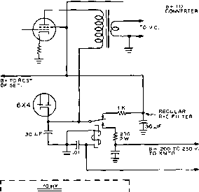 6 V. VIA CONTROL RELAY IN XMTR. + FROM [ t B+ TO LOW POWER ECEIVER-1- -L В F AND SPEECH -pjjFeT STAGES xmtr the screens of a push*pull stage are connected to the input side instead of the output side of the power supply filter (usually two electroly-tics straddling a resistor in an R-C filter), then follow the оифиг of the filter over into the r-f portion of the set and pick it up there at a convenient point, before it goes through any additional series dropping or isolating resistors, as shown in figure 2. The voltage at the output of the filter usually runs from 200 to 250 volts with typical converter drain and the motor not running. This will increase perhaps 10 per cent when the generator is charging. The converter drain will drop the В voltage slightly at the output of the filter, perhaps 15 to 25 volts, but this reduction is not enough to have a noticeable effect upon the operation of the receiver. If the В voltage is higher than desirable or necessary for proper operation of the converter, a 2-watt carbon resistor of suitable resistance should be inserted in series with the plate voltage lead to the power receptacle. Usually something between 2200 and 4700 ohms will be foimd about right. F=rgure 2 USING THE RECEIVER PLATE SUPPLY FOR THE TRANSMITTER This circuit silences the receiver on transmit, and in addition makes it possible ta use the receiver plate supply far feeding the exciter and speech amplifier stages in the transmitter. is to mount a small receptacle on the receiver cabinet or chassis, making connection via a matching plug. An Amphenol type 77-26 receptacle is compact enough to fit in a very small space and allows four connections (including ground for the shield braid). The matching plug is a type 70-26. To avoid the possibility of vibrator hash being fed into the converter via the heater and piate voltage supply leads, it is important that the heater and plate voltages be taken from points well removed from the power supply portion of the auto receiver. If a single-ended audio output stage is employed, a safe place to obtain these voltages is at this tube socket, the high voltage for the converter being taken from the screen. In the case of a push-pull output stage, however, the screens sometimes are fed from the input side of the power supply filter. The ripple at this point, while sufficiently low for a push-pull audio output stage, is not adequate for a converter without additional filtering. If the schematic shows that Receiver Disabling When the battery drain is on Transmit high on transmit, as is the case when a PE-103A dy-namotor is run at maximum rating and other drains such as the transmitter heaters and auto headlights must be considered, it is desirable to disable the vibrator power supply in the receiver during transmissions. The vibrator power supply usually draws several amperes, and as the receiver must be disabled in some manner anyhow during transmissions, opening the 6-volt supply to the vibrator serves both purposes. It has the further advantage of introducing a slight delay in the receiver recovery, due to the inertia of the power supply filter, thus avoiding the possibility of a feedback yoop when switching from transmit to receive. To avoid troubles from vibrator hash, it is best to open the ground lead from the vibrator by means of a midget s.p.d.t. 6-volt relay and thus isolate the vibrator circuit from the external control and switching circuit wires. The relay is hooked up as shown in figure 3: Standard 8-ampere contacts will be adequate for this application. The relay should be mounted as close to the vibrator as practicable. Ground one of the coil terminals and run a shielded wire from the other coil terminal to one of the power receptacle cormections, grounding the shield at both ends. By-pass each end of this wire to ground with .01 fiid., using the shortest possible leads. A lead is run from the corresponding terminal on the mating plug to the control circuits, to be discussed later. KEEP THESE LEADS SHORT OR SHIELD THEM. S.P.D.T. 6 V, DC.  TO HOT SIDE OF VOICE COIL WINDING - О 6 V- VIA CONTROL ~ RELAY IN XMTR. Figure 3 METHOD OF ELIMINATING THE BATTERY DRAIN OF THE RECEIVER VIBRATOR PACK DURING TRANSMISSION If the receiver chassis hos room for a midget s.p.J.t. relay, the obove orrongemenf not only silences the receiver on transmit but saves several amperes battery drain. If the normally open contact on the relay is connected to the hot side of the voice coil winding as shown in figure 3 (assuming one side of the voice coil is grounded in accordance with usual practice), the receiver will be killed instantly when switching from receive to transmit, in spite of the fact that the power supply filter in the receiver takes a moment to discharge. However, if a slow start power supply (such as a dynamotor or a vibrator pack with a large filter) is used with the transmitter, shorting the voice coil probably will not be required. Using the Receiver An alternative and high-Plqfe Supply ly recommended proce- On Tronsmit dure is to make use of the receiver В supply on transmit, instead of disabling it. One disadvantage of the popular PE-103A dynamotor is the fact that its 450-500 volt output is too high for the low power r-f and speech stages of the transmitter. Dropping this voltage to a more suitable value of approximately 250 volts by means of dropping resistors is wasteful of power, besides causing the plate voltage on the oscillator and any buffer stages to vary widely with tuning. By means of a midget 6-volts.p.d.t. relay mounted in the receiver, connected as shown in figure 2, the В suRjly of the auto set is used to power the oscillator and other low power stages (and possibly screen voltage on the modulator). On transmit the В voltage is removed from the receiver and converter, automatically silencing the receiver. When switching to receive the trans- mitter oscillator is killed instantly, thus avoiding trouble from dynamotor carry over. The efficiency of this arrangement is good because the current drain on the main high voltage supply for the modulated amplifier and modulator plate(s) is reduced by the amount of current borrowed from the receiver. At least 80 ma. can be drawn from practically all auto sets, at least for a short period, without damage. It will be noted that with the arrangement of figure 2, plate voltage is supplied to the audio output stage at all times. However, when the screen voltage is removed, the plate current drops practically to zero. The 200-ohm resistor in series with the nor-nlly open contact is to prevent excessive sparking when the contacts close. If the relay feeds directly into a filter choke or large capacitor there will be excessive sparking at the contacts. Even with the arrangement shown, there will be considerable sparking at the contacts; but relay contacts can stand such sparking quite a while, even on d.c, before becoming worn or pitted enough to require attention. The 200-ohm resistor also serves to increase the effectiveness of the .01-/ifd. r-f by-pass capacitor. Auxiliary Antenna One other modification of Trimmer the auto receiver which may or may not be desirable depending upon the circumstances is the addition of an auxiliary anterma trimmer capacitor. If the converter uses an untuned output circuit and the antenna trimmer on the auto set is peaked with the converter cut in, then it is quite likely that the trimmer adjustment will not be optimum for broadcast-band reception when the converter is cut out. For reception of strong broadcast band signals this usually will not be serious, but where reception of weak broadcast signals is desired the loss in gain often cannot be tolerated, especially in view of the fact that the additional length of antenna cable required for the converter installation tends to reduce the strength of broadcast band signals. If the converter has considerable reserve gain, it may be practicable to peak the antenna trimmer on the auto set for broadcast-band reception rather than resoiwting it to the converter output circuit. But oftentimes this results in insufficient converter gain, excessive image troubles from loud local amateur stations, or both. The difficulty can be circumvented by incorporation of an auxiliary antenna trimmer connected from the hot antenna lead on the auto receiver to ground, with a switch in series for cutting it in or out. This capacitor and switch can be connected across either the converter end or the set end of the cable between the converter and receiver. This auxiliary trimmer should have a range of about 3 to 50 lifiid., and may be of the inexpensive compression mica type. With the trimmer cut out and the converter turned off (by-passed by the in-out switch), peak the regular antenna trimmer on the auto set at about 1400 kc. Then turn on the converter, with the receiver tuned to 1500 kc, switch in the auxiliary trimmer, and peak this trimmer for maximum background noise. The auxiliary trimmer then can be left switched in at all times except when receiving very weak broadcast band signals. Some auto sets, particularly certain General Motors custom receivers, employ a high-Q high-impedance input circuit which is very critical as to antenna capacitance. Unless the shunt capacitance of the antenna (including cable) approximates that of the antenna installation for which the set was designed, the antenna trimmer on the auto set cannot be made to hit resonance with the converter cut out. This is particularly true when a long antenna cable is used to reach a whip mounted at the rear of the car. Usually the condition can be corrected by unsoldering the internal connection to the antenna terminal connector on the auto set and inserting in series a 100-fi(ifd. mica capacitor. Alternatively an adjustable trimmer covering at least 50 to 150 ццМ. may be substituted for the 100-fifd. fixed capacitor. Then the adjustment of this trimmer and that of the regular antenna trimmer can be juggled back and forth until a condition is achieved where the input circuit of the auto set is resonant with the converter either in or out of the circuit. This will provide maximum gain and image rejection under all conditions of use. Reducing Battery When the receiving installa-Droin of the tion is used frequently, and Receiver particularly when the receiv- er is used with the car parked, it is desirable to keep the battery drain of the receiver-converter installation at an absolute minimum. A substantial reduction in drain can be made in many receivers, without appreciably affecting their performance. The saving of course depends upon the design of the particular receiver and upon how much trouble and expense one is willing to go to. Some receivers normally draw (without the converter connected) as much as 10 amperes. In many cases this can be cut to about 5 amperes by incoфorating all practicable modifications. Each of the following modifications is applicable to many auto receivers. If the receiver uses a speaker with a field coil, replace the speaker with an equivalent PM type. Practically all 0.3-ampere r-f and a-f voltage amplifier tubes have 0.15-arapere equivalents. In many cases it is not even necessary to change the socket wiring. However, when substituting i-f tubes it is recommended that the i-f trimmer adjustments be checked. Generally speaking it is not wise to attempt to substitute for the converter tube or a-f power оифиг tube. If the a-f output tube employs conventional cathode bias, substitute a cathode resistor of twice the value originally employed, or add an identical resistor in series with the one already in the set. This will reduce the В drain of the receiver appreciably without seriously reducing the maximum undistorted output. Because the vibrator power supply is much less than 100 per cent efficient, a saving of one watt of В drain results in a saving of nearly 2 watts of battery drain. This also minimizes the overload on the В supply when the converter is switched in, assuming that the converter uses В voltage from the auto set. If the receiver uses push-pull output and if one is willing to accept a slight reduction in the maximum volume obtainable without distortion, changing over to a single ended stage is simple if the receiver employs conventional cathode bias. Just pull out one tube, double the value of cathode bias resistance, and add a 25-fifd. by-pass capacitor across the cathode resistor if not already by-passed. In some cases it may be possible to remove a phase inverter tube along with one of the a-f output tubes. If the receiver uses a motor driven station selector with a control tube (d-c amplifier), usually the tube can be removed without upsetting the operation of the receiver. One then must of course use manual tuning. While the changeover is somewhat expensive, the 0.6 ampere drawn by a 6X4 or 6X5 rectifier can be eliminated by substituting six 115-volt r-m-s 50-ma. selenium rectifiers (such as Federal type 402D3200). Three in series are substituted for each half of the full-wave rectifier tube. Be sure to observe the correct polarity. The selenium rectifiers also make a good substitution for an 0Z4 or 0Z4-GT which is causing hash difficulties when using the converter. Offsetting the total cost of nearly $4.00 is the fact that these rectifiers probably will last for the entire life of the auto set. Before purchasing the rectifiers, make sure that there is room available for mounting them. While these units are small, most of the newer auto sets employ very compact construction. Two-liAeter Reception For reception on the 144-Mc. amateur band, and those higher in frequency, the simple converter- 1 ... 48 49 50 51 52 53 54 ... 80 |
|
© 2026 AutoElektrix.ru
Частичное копирование материалов разрешено при условии активной ссылки |