 |
 |
 |
| Главная Журналы Популярное Audi - почему их так назвали? Как появилась марка Bmw? Откуда появился Lexus? Достижения и устремления Mercedes-Benz Первые модели Chevrolet Электромобиль Nissan Leaf |
Главная » Журналы » Simple coaxial reflectometer 1 ... 49 50 51 52 53 54 55 ... 80 One-Tube Converter auto-set combination has not proven very satisfactory. The primary reason for this is the fact that the relatively sharp i-f channel of the auto set imposes too severe a limitation on the stability of the high-frequency oscillator in the converter. And if a crystal-controlled beating oscillator is used in the converter, only a portion of the band may be covered by tuning the auto set. The most satisfactory arrangement has been found to consist of a separately mounted i.f., audio, and power supply system, with the converter mounted near the steering column. The i-f system should have a bandwidth of 30 to 100 kc. and may have a center frequency of 10.7 Mc. if standard i-f transformers are to be used. The control head may include the 144-Mc. r-f, mixer, and oscillator sections, and sometimes the first i-f stage. Alternatively, the control head may include only the h-f oscillator, with a broadband r-f unit included within the main receiver assembly along with the i.f. and audio system. Commercially manufactured kits and complete units using this general lineup are available. An alternative arrangement is to build a converter, 10.7-Mc. i-f channel, and second detector unit, and then to operate this unit in conjunction with the auto-set power supply, audio system, and speaker. Such a system makes economical use of space and power drain, and can be switched to provide normal broadcast-band auto reception or reception through a converter for the h-f amateur bands, A recent development has been the VHF transceiver, typified by the Gonset Communicator. Such a unit combines a crystal controlled transmitter and a tunable VHF receiver together with a common audio system and power supply. The complete VHF station may be packaged in a single cabinet. Various forms of VHF transceivers are shown in the construction chapters of this Handbook. 26-2 Mobile Transmitters As in the case of transmitters for fixed-station operation, there are many schools of thought as to the type of transmitter which is most suitable for mobile operation. One school states that the mobile transmitter should have very low power drain, so that no modification of the electrical system of the automobile will be required, and so that the equipment may be Operated without serious regard to discharging the battery when the car is stopped, or overloading the generator when the car is in mo- tion. A total transmitter power drain of about 80 watts from the car battery (6 volts at 13 amperes, or 12 volts at 7 amperes) is about the maximum that can be allowed under these conditions. For maximum power efficiency it is recommended that a vibrator type of supply be used as opposed to a dynamotor supply, since the conversion efficiency of the vibrator unit is high compared to that of the dynamotor, A second school of thought states that the mobile transmitter should be of relatively high power to overcome the poor efficiency of the usual mobile whip antenna. In this case, the mobile power should be drawn from a system that is independent from the electrical system of the automobile, A belt driven high voltage generator is often coupled to the automobile engine in this type of installation. A variation of this idea is to employ a complete secondary power system in the car capable of providing 115 volts a.c. Shown in figure 4 is a Leece-Neville three phase alternator mounted atop the engine block, and driven with a fan belt. The voltage regulator and selenium rectifier for charging the car battery from the a-c system replace the usual d-c generator. These new items are mounted in the front of the car radiator. The alternator provides a balanceddeltaoutput circuit wherein the line voltage is equal to the coil voltage, but the line current isY3 times the coil current. The coil voltage is a nominal 6-volts, RMS and three 6.3 volt 25 ampere filament transformers may be connected in delta on the primary and secondary windings to step the 6-volts up to three-phase 115-volts. If desired, a special 115-volt, 3-phase step-up transformer may be wound which will occupy less space than the three f i 1 am e n t transformers. Since the ripple frequency of a three phase d-c power supply will be quite high, a single 10 mfd filter capacitor will suffice.  Figure 4 LEECE-NEVILLE 3-PHASE ALTERNATOR IS ENGINE DRIVEN BY AUXILIARY FAN BELT.  Figure 5 A CENTER LOADED SO-METER WHIP USING AIR WOUND COIL MAY BE USED WITH HIGH POWERED TRANSMITTERS An anti-corona loop is placed at the top of the whip to reduce loss of power and burning of tip of antenna. Number of turns in coil is critical and adjustable, high-Q coil is recommended. Whip may be used over frequency range of about 15 kilocycles without retuning. 26-3 Antennas for Mobile Work 10-Meter Mobile The most popular mobile an-Antennos tenna for 10-meter operation is a rear-mounted whip approximately 8 feet long, fed with coaxial line. This is a highly satisfactory antenna, but a few 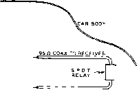 75 л COAX TO XMTH Figure 6 5/16.WAVE WHIP RADIATOR FOR 10 METERS If a whip antenna Is made slightly longer than ane-quarter wave it acts as a slightly better radiator than the usual quarter-wave whip, and it can provide a better match to the antenna transmission line If the reactance Is tuned out by a series capacitor close to the base of the antenna. Capacitor Cj may be a 100-p.pi.fd. midget variable. remarks are in order on the subject of feed and coupling systems. The feed point resistance of a resonant quarter-wave rear-mounted whip is approximately 20 to 25 ohms. While the standing-wave ratio when using 50-ohm coaxial line will not be much greater than 2 to 1, it is nevertheless desirable to make the line to the transmitter exactly one quarter wavelength long electrically at the center of the band. This procedure will minimize variations in loading over the band. The physical length of RG-8/U cable, from antenna base to antenna coupling coil, should be approximately 5 feet 3 inches. The antenna changeover relay preferably should be located either at the antenna end or the transmitter end of the line, but if it is more convenient physically the line may be broken anywhere for insertion of the relay. If the same rear-mounted whip is used for broadcast-band reception, attenuation of broadcast-band signals by the high shunt capacitance of the low impedance feed line can be reduced by locating the changeover relay right at the antenna lead in, and by running 95-ohm coax (instead of 50 or 75 ohm coax) from the relay to the converter. Ordinarily this will produce negligible effect upon the operation of the converter, but usually will make a worthwhile improvement in the strength of broadcast-band signals. A more effective radiator and a better line match may be obtained by making the whip approximately 10/ feet long and feeding it with 75-ohm coax (such as RG-ll/U) via a series capacitor, as shown in figure 6. The relay and series capacitor are mounted inside the trunk, as close to the antenna feedthrough or base-mount insulator as possible. The 10 \4-foot length applies to the overall length from the tip of the whip to the point where the lead in passes through the car body. The leads inside the car (connecting the coaxial cable, relay, series capacitor and anteima lead) should be as short as possible. The outer conductor of both coaxial cables should be grounded to the car body at the relay end with short, heavy conductors. A 100-fitfd. midget variable capacitor is suitable for C,. The optimum setting should be determined experimentally at the center of the band. This setting then will be satisfactory over the whole band. One suitable coupling arrangement for either a %-va.ve or 5/l6-wave whip on 10 meters is to use a conventional tank circuit, inductively coupled to a variable link coupling loop which feeds the coaxial line. Alternatively, a pi-network output circuit may be used. If the input impedance of the line is very low and the tank circuit has a low C/L ratio, it may be necessary to resonate the coupling loop with series capacitance in order to obtain sufficient coupling. This condition often is encountered with a !4-wave whip when the line length approximates an electrical half wavelength. If an all-band center-loaded mobile antenna is used, the loading coil at the center of the antenna may be shorted out for operation of the antenna on the 10-meter band. The usual type of center-loaded mobile antenna will be between 9 and 11 feet long, including the center-loading inductance which is shorted out. Hence such an antenna may be shortened to an electrical quarter-wave for the 10-meter band by using a series capacitor as just discussed. Alternatively, if a pi-network is used in the plate circuit of the output stage of the mobile transmitter, any reactance presented at the antenna terminals of the transmitter by the antenna may be tuned out with the pi-network. The All-Band The great majority of mobile Center-Loaded operation on the 14-Mc. band Mobile Antenna and below is with center loaded whip antennas. These antennas use an insulated bumper or body mount, with provision for coaxial feed from the base of the antenna to the transmitter, as shown in figure 7. The center-loaded whip antetma must be .САЯ BODY UNSHIELDED LOADING COIL RG-58/U LINE TO TRANSMITTER  COAX lAL LINE GHOUNDED TO FRAME OF CAR ADJACENT TO BASE OF ANTENNA Fi gure 7 THE CENTER-LOADED WHIP ANTENNA Tbe center-loaded whip antenna, when provided with a tapped loading coil or a series of coils, may be used over a wide frequency range. The loading coil may be shorted for use of the antenna on the 10-meter band. tuned to obtain optimum operation on the desired frequency of operation. These antennas will operate at maximum efficiency over a range of perhaps 20 kc. on the 75-meter band, covering a somewhat wider range on the 40-meter band, and covering the whole 20-meter phone band. The procedure for tuning the antennas is discussed in the instruction sheet which is furnished with them, but basically the procedure is as follows: The antenna is installed, fully assembled, with a coaxial lead of RG-58/U from the base of the antenna to the place where the transmitter is installed. The rear deck of the car should be closed, and the car should be parked in a location as clear as possible of trees, buildings, and overhead power lines. Objects within 15 or 20 feet of the antenna can exert a considerable detuning effect on the antenna system due to its relatively high operating Q. The end of the coaxial cable which will plug into the transmitter is terminated in a link of 3 or 4 turns of wire. This link is then coupled to a grid-dip meter and the resonant frequency of the antenna determined by noting the frequency at which the grid current fluctuates. The coils furnished with the antennas normally are too large for the usual operating frequency, since it is much easier to remove turns than to add them. Turns then are removed, one at a time, until the antenna resonates at the desired frequency. If too many turns have been removed, a length of wire may be spliced on and soldered. Then, with a length of insulating tubing slipped over the soldered joint, turns may be added to lower the resonant fre- 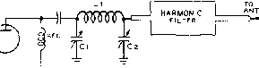 Figure 8 PI-NETWORK ANTENNA COUPLER The pi-network antenno coupler is particularly satisfactory far mobile work since the coupler affords some degree of harmonic reduction, provides a coupling variation to meet varying load conditions caused by frequency chonges, and can cancel out reactance presented to the transmitter at the end of the antenna transmission line. For use of the coupler on the 3,9-Mc. band Cl should have a maximum capacitance af about 250 lJ.fJi.fd., Ll should be about 9 microhenrys (30 turns I dia. by 2 long), and Cj may include a fixed and a variable element with maximum capacitance of about 1400 fifJ-fd. A 100-fJ.fJ.fd. variable capacitor will be suitable at Ci for the 14-Mc. and 28-Mc. bands, with a SSO.fififd. variable at C2. Inductor Ll should have an Inductance of o-boot 2 microhenrys (11 turns 1 dia. by l long) for the 14-Mc. band, and about 0.8 microhenry (6 turns 1 dia, by 1 long) for the 28-Mc. band. quency. Or, if the tapped type of coil is used, taps are changed until the proper number of turns for the desired operating frequency is found. This procedure is repeated for the different bands of operation. Feeding the After much experimenting it Center-Loaded has been found that the most Antenna satisfactory method for feed- ing the coaxial line to the base of a center-loaded antenna is with the pi-network coupler. Figure 8 shows the basic arrangement, with recommended circuit constants. It will be noted that relatively large values of capacitance are required for all bands of operation, with values which seem particularly large for the 75-meter band. But reference to the discussion of pi-network tank circuits in Chapter 13 will show that the values suggested are normal for the values of impedance, impedance transformation, and operating Q which are encountered in a mobile installation of the usual type. 26-4 Construction and Installotion oi Mobile Equipment It is recommended that the following measures be taken when constructing mobile equipment, either transmitting or receiving, to ensure trouble-free operation over long periods: Use only a stiff, heavy chassis unless the chassis is quite small. Use lock washers or lock nuts when mounting components by means of screws. Use stranded hook-up wire except where r-f considerations make it inadvisable (such as for instance the plate tank circuit leads in a v-h-f amplifier). Lace and tie leads wherever necessary to keep them from vibrating or flopping around. Unless provided with gear drive, tuning capacitors in the large sizes will require a rotor lock. Filamentary (quick heating) tubes should be mounted only in a vertical position. The larger size carbon resistors and mica capacitors should not be supported from tube socket pins, particularly from miniature sockets. Use tie points and keep the resistor and capacitor pigtails short. Generally speaking, rubber shock mounts are unnecessary or even undesirable with passenger car installations, or at least with full size passenger cars. The springing is sufficiently soft that well constructed radio equipment can be bolted directly to the vehicle without damage from shock or vibration. Unless shock mounting is properly engineered as to the stiffness and placement of the shock mounts, mechanical-resonance amplification effects may actually cause the equipment to be shaken more than if the equipment were bolted directly to the vehicle. Surplus military equipment provided with shock or vibration mounts was intended for use in aircraft, jeeps, tanks, gun-firing Naval craft, small boats, and similar vehicles and craft subject to severe shock and vibration. Also, the shock mounting of such equipment is very carefully engineered in order to avoid harmful resonances. To facilitate servicing of mobile equipment, all interconnecting cables between units should be provided with separable connectors on at least one end. Control Circuits The send-receive control circuits of a mobile installation are dictated by the design of the equipment, and therefore will be left to the ingenuity of the reader. However, a few generalizations and suggestions are in order. Do not attempt to control too many relays, particularly heavy duty relays with large coils, by means of an ordinary push-to-talk switch on a microphone. These contacts are not designed for heavy work, and the inductive kick will cause more sparking than the contacts on the microphone switch are designed to handle. It is better to actuate a single relay with the push-to-talk switch and then control all other relays, including the heavy duty contactor for the dynamotor or vibrator pack, with this relay. The procedure of operating only one relay direcdy by the push-to-talk switch, with all other relays being controlled by this control relay, will eliminate the often-encountered difficulty where the shutting down of one item of equipment will close relays in other items as a result of the coils of relays being placed in series with each other and with heater circuits. A recommended general control circuit, where one side of the main control relay is connected to the hot 6-volt circuit, but all other relays have one side connected to ground, is illustrated in figure 9- An additional advantage of such a circuit is that only one control wire need be run to the coil of each additional relay, the other side of the relay coils being grounded. The heavy-duty 6-volt solenoid-type contactor relays such as provided on the PE-103A and used for automobile starter relays usually draw from 1.5 to 2 amperes. While somewhat more expensive, heavy-duty 6-volt relays of conventional design, capable of breaking 30 amperes at 6 volts d.c, are available with coils drawing less than 0.5 ampere. When purchasing relays keep in mind that the current rating of the contacts is not a fixed value, but depends upon (1) the voltage, (2) whether it is a.c. or d.c, and (3) whether the circuit is purely resistive or is inductive. If in doubt, refer to the manufacturers recommendations. Also keep in mind that a dynamotor presents almost a dead short until the armature starts turning, and the starting relay should be rated at considerably raore than the normal dynamotor current. Microphones The most generally used micro-ond Circuits phone for mobile work is the single-button carbon. With a high-output-type microphone and a high-ratio microphone transformer, it is possible when close talking to drive even a pair of push-pull 6l6s without resorting to a speech amplifier. However, there is a wide difference in the output of the various type single button microphones, and a wide difference in the a-mount of step up obtained with different type microphone transformers. So at least one speech stage usually is desirable. One of the most satisfactory single button PUSH-TO-TALK SWITCH ON MIKE PUSH-TO-TALK RELAV J l-\ l-\ l-\ Ч ALTERNATE CONTROL SWITCH MAIN POWER RECEIVER ANTENNA RELAV MUTING CHANGEOVER RELAY RELAY ANY OTHER RELAYS Figure 9 RELAY CONTROL CIRCUIT Simplified schematic af the recommended relay control circuit for mobile transmitters. The relatively small push-totalh relay Is controlled by the button an the microphone or the communications switch. Then one of the contacts on this relay controls the other relays of the transmitter; one side of the coil of all the additional relays controlled should be grounded. microphones is the standard Western Electric type F-1 unit (or Automatic Electric Co. equivalent). This microphone has very high output when operated at 6 volts, and good fidelity on speech. When used without a speech amplifier stage the microphone transformer should have a 50-ohm primary (rather than 200 or 500 ohms) and a secondary of at least 150,000 ohms and preferably 250,000 ohms. The widely available зиф1и5 type T-17 microphone has higher resistance (200 to 500 ohms) and lower output, and usually will require a stage of speech amplification except when used with a very low power modulator stage. Unless an F-1 unit is used in a standard housing, making contact to the button presents somewhat of a problem. No serious damage will result from soldering to the button if the connection is made to one edge and the soldering is done very rapidly with but a small a-mount of solder, so as to avoid heating the \Aole button. A sound-powered type microphone removed from one of the chest sets available in the surplus market will deliver almost as much voltage to the grid of a modulator stage when used with a high-ratio microphone transformer as will an F-1 unit, and has the advantage of not requiring button current or a hash filter. This is simply a dynamic microphone designed for high output rather than maximum fidelity. The standardized connections for a single-button carbon microphone provided with push-to-talk switch are shown in figure 10. Practically all hand-held military-type single-button 1Г RINS tip - SHELL [GROUND) OF MIKE PLUG PRESS-TO-TALK SWITCH Figure 10 STANDARD CONNECTIONS FOR THE PUSH-TO-TALK SWITCH ON A HANDHELD SINGLE-BUTTON CARBON MICROPHONE microphones on the surplus market use these connections. There is an increasing tendency among mobile operators toward the use of microphones having better frequency and distortion characteristics than the standard single-button type. The high-impedance dynamic type is probably the most popular, with the ceramic-crystal type next in popularity. The conventional crystal type is not suitable for mobile use since the crystal unit will be destroyed by the high temperatures which can be reached in a closed car parked in the sun in the summer time. The use of low-level microphones in mobile service requires careful attention to the elimination of common-ground circuits in the microphone lead. The ground connection for the shielded cable which runs from the transmitter to the microphone should be made at only one point, preferably directly adjacent to the grid of the first tube in the speech amplifier. The use of a low-level microphone usually will require the addition of two speech stages (a pentode and a triode), but these stages will take only a milliampere or two of plate current, and 150 ma. per tube of heater current. PE-103A Dyno- Because of its availability motor Power Unit on the surplus market at a low price and its suitability for use with about as powerful a mobile transmitter as can be employed in a passenger car without resorting to auxiliary batteries or a special generator, the PE-103A is probably the most widely used dynamotor for amateur work. Therefore some useful information will be given on this unit. The nominal rating of the unit is 500 volts and l60 ma., but the output voltage will of course vary with load and is slightly higher with the generator charging. Actually the 160 ma. rating is conservative, and about 275 ma. can be drawn intermittendy without overheating, and without damage or excessive brush or commutator wear. At this current the unit should not be run for more than 10 minutes at a time, and the average on time should not be more than half the average off time. The output voltage vs. current drain is shown approximately in figure 11. The exact voltage will depend somewhat upon the loss resistance of the primary connecting cable and whether or not the battery is on charge. The primary current drain of the dynamotor proper (excluding relays) is approximately 16 amperes at 100 ma., 21 amperes at 160 ma., 26 amperes at 200 ma., and 31 amperes at 250 ma. Only a few of the components in the base are absolutely necessary in an amateur mobile installation, and some of them can just as well be made an integral part of the transmitter if desired. The base can be removed for salvage components and hardware, or the dynamotor may be purchased without base. To remove the base proceed as follows; Loosen the four thumb screws on the base plate and remove the cover. Remove the four screws holding the dynamotor to the base plate. Trace the four wires coming out of the dynamotor to their terminals and free the lugs. Then these four wires can be pulled through the two rubber grommetsin the base plate when the dynamotor is separated from the base plate. It may be necessary to bend the eyelets in the large lugs in order to force them through the grommets. Next remove the two end housings on the dynamotor. Each is held with two screws. The high-voltage commutator is easily identified by its narrower segments and larger diameter. Next to it is the 12-volt commutator. The 6-volt commutator is at the other end of the armature. The 12-volt brushes should be removed when only 6-volt operation is plaimed, in order to reduce the drag. If the dynamotor portion of the PE-103A power unit is a Pioneer type VS-25 or a Russell type 530- (most of them are), the wires to the 12-volt brush holder terminals can be cross coimected to the 6-voIt brush holder terminals with heavy jumper wires. One of the wires disconnected from the 12-volt brush terminals is the primary 12-volt pigtail and will come free. The other wire should be cotmected to the opposite terminal to form one of the jumpers. With this arrangement it is necessary only to remove the 6-volt brushes and replace the 12-volt brushes in case the 6-volt commutator becomes excessively dirty or worn or starts throwing solder. No difference in output voltage will be noted, but as the 12-volt brushes are not as heavy as the 6-volt brushes it is not permissible to draw more than about 150 ma. except for emergency use until the 6-volt commutator can be turned down or repaired. < I- i о > Э H Л50 О
ISO 200 250 OUTPUT CURRENT, MA, Figure П APPROXIMATE OUTPUT VOLTAGE VS. LOAD CURRENT FOR A PE-103A DYNAMOTOR At 150 ma. or less the 12-volt brushes will last almost as long as the 6-volt brushes. The reason that these particular dynamotCKs can be operated in this fashion is that there are two 6-volt windings on the armature, and for 12-volt operation the two are used in series with both commutatOTs working. The arrangement described above simply substitutes for the regular 6-volt winding the winding and commutator which ordinarily came into operation only on 12-volt operation. Some operators have reported that the regulation of the РЕ-ЮЗА may be improved by operating both commutators in parallel with the 6-voIt line. The three wires now coming out of the dynamotor are identified as follows: The smaller wire is the positive high voltage. The heavy wire leaving the same gronmnet is positive 6 volts and negative high voltage. The single heavy wire leaving the other grommet is negative 6 volts. Whether the car is positive or negative ground, negative high voltage can be taken as car-frame ground. With the negative of the car battery grounded, the plate current can return through the car battery and the armature winding. This simply puts the б volts in series with the 500 volts and gives 6 extra volts plate voltage. The trunk of a car gets very warm in summer, and if the transmitter and dynamotor are mounted in the trunk it is recommended that the end housings be left off the dynamotor to facilitate cooling. This is especially impor-taiu in hot climates if the dynamotor is to be loaded to more than 200 ma. When replacing brushes on aPE-103A check to see if the brushes are marked negative and positive. If so, be sure to install them accordingly, because they ate not of the same material. The dynamotor will be marked to show which holder is negative. When using a PE-103A, or any dynamotor for that matter, it may be necessary to devote one set of contacts on one of the control relays to breaking the plate or screen voltage to the transmitter oscillator, If these are supplied by the dynamotor, because the output of a dynamotor takes a moment to fall to zero when the primary power is removed. 26-5 Vehiculor Noise Suppression Satisfactory reception on frequencies above the broadcast band usually requires greater attention to noise suppression measures. The required measures vary with the particular vehicle and the frequency range involved. Most of the various types of noise that may be present in a vehicle may be broken down into the following main categories: (1) Ignition noise. (2) Wheel static (tire static, brake static, and intermittent ground via front wheel bearings). (3) Hash from voltage regulator contacts. (4) 1Ъ1пе from generator commutator segment make and break. (5) Static from scraping connections between various parts of the car. There is no need to suppress ignition noise completely, because at the higher frequencies ignition noise from passing vehicles makes the use of a noise limiter mandatory anyway. However, the limiter should not be given too much work to do, because at high engine speeds a noisy ignition system will tend to mask weak signals, even though with the limiter working, ignition pops may appear to be completely eliminated. Another reason for good ignition suppression at the source is that strong ignition pulses contain enough energy when integrated to block the a-v-c circuit of the receiver, causing the gain to drop whenever the engine is speeded up. Since the a-v-c circuits of the receiver obtain no benefit from a noise clipper, it is important that ignition noise be suppressed enough at the source that the a-v-c circuits will not be affected even when the engine is ruiming at high speed. Ignition Noise The following procedure should be found adequate for reducing the ignition noise of practically any passenger car to a level which the clipper can handle satisfactorily at any engine speed at any frequency from 500 kc. to 148 Mc. Some of the measures may already have been taken when the auto receiver was installed. First either install a spark plug suppressor on each plug, or else substitute Autolite resistor plugs. The latter are more effective than suppressors, and on some cars ignition noise is reduced to a satisfactory level simply by installing them. However, they may not do an adequate job alone after they have been in use for a while, and it is a good idea to take the following additional measures. Check all high tension connections for gЩ>s, particularly the pinch fit terminal connectors widely used. Replace old high tension wiring that may have become leaky. Check to see if any of the high tension wiring is cabled with low tension wiring, or run in the same conduit. If so, reroute the low tension wiring to provide as much separation as practicable. By-pass to ground the 6-volt wire from the ignition coil to the ignition switch at each end with a 0.1-frfd. molded case per capacitor in parallel with a .001-fifd. mica or ceramic, using the shortest possible leads. Check to see that the hood makes a good ground contact to the car body at several points. Special grounding contactors are available for attachment to the hood lacings on cars that otherwise would present a grounding problem. If the high-tension coil is mounted on the dash, it may be necessary to shield the high tension wire as far as the bulkhead, unless it already is shielded with armored conduit. Wheel Static Wheel Static is either static electricity generated by rotation of the tires and brake drums, or is noise generated by poor contact between the front wheels and the axles (due to the grease in the bearings). The latter type of noise seldom is caused by the rear wheels, but tire static may of course be generated by all four tires. Wheel static can be eliminated by insertion of grounding springs under the front hub caps, and by inserting tire powder in all inner tubes. Both items are available at radio parts stores and from most auto radio dealers. Voltage Regulator Hash Certain voltage regulators generate an objectionable amount of hash at the higher frequencies, particularly in the v-h-f range. A large by-pass will affect the operation of the regulator and possibly damage the points. A small by-pass can be used, however, without causing trouble. At frequencies above the frequency at which the hash becomes objectionable (approximately 20 Mc. or so) a small by-pass is quite effective. A 0.001-/rfd. mica capacitor placed from the field terminal of the regulator to ground with the shortest possible leads often will produce sufficient improvement. If not, a choke consisting of a-bout 60 turns of no. 18 d.c.c. or bell wire wound on a -inch form can be added. This should be placed right at the regulator terminal, and the 0.001-fifd. by-pass placed from the generator side of the choke to ground. Generator Whine Generator whine often can be satisfactorily suppressed from 550 kc. to 148 Mc. simply by by-passing the armature Terminal to ground with a special auto radio by-pass of 0.25 or 0.5 fiid. in parallel with a 0.001-/ifd. mica or ceramic capacitor. The former usually is placed on the generator when an auto radio is installed, but must be augmented by a mica or ceramic capacitor with short leads in order to be effective at the higher frequencies as well as on the broadcast band. When more drastic measures are required, special filters can be obtained which are designed for the purpose. These are recommended for stubborn cases when a wide frequency range is involved. For reception only over a comparatively narrow band of frequencies, such as the 10-meter amateur band, a highly effective filter can be improvised by coimect-ing between the previously described parallel by-pass capacitors and the generator armature terminal a resonant choke. This may consist of no. 10 enamelled wire wound on a suitable form and shunted with an adjustable trimmer capacitor to permit resonating the combination to the center of the frequency band involved. For the 10-meter band 11 turns close wound on a one-inch form and shunted by a 3-30 fififd. compression-type mica trimmer is suitable. The trimmer should be adjusted experimentally at the center frequency. When generator whine shows up after once being satisfactorily suppressed, the condition of the brushes and commutator should be checked. Unless a by-pass capacitor has opened up, excessive whine usually indicates that the brushes or commutator are in need of attention in order to prevent damage to the generator. Body Static Loose linkages or body or frame joints anywhere in the car are potential static producers when the car is in motion, particularly over a rough road. Locating the source of such noise is difficult, and the simplest procedure is to give the car a thorough tightening up in the hope that the offending poor contacts will be caught by the procedure. The use of braided bonding straps between the various sections of the body of the car also may prove helpful. Miscellaneous There are several other potential noise sources on a passenger vehicle, but they do not necessarily give trouble and therefore require attention only in some cases. The heat, oil pressure, and gas gauges can cause a rasping or scraping noise. The gas gauge is the most likely offender. It will cause trouble only when the car is rocked or is in motion. The gauge units and panel indicators should both be by-passed with the O.l-jitfd. paper and 0,001-;/fd, mica or ceramic combination previously described. At high car speeds under certain atmospheric conditions corona static may be encountered unless means are taken to prevent it. The receiving-type auto whips which employ a plastic ball tip are so provided in order to minimize this type of noise, which is simply a discharge of the frictional static built up on the car. A whip which ends in a relatively sharp metal point makes an ideal discharge point for the static charge, and will cause corona trouble at a much lower voltage than if the tip were hooded with insulation. A piece of Vinylite sleeving slipped over the top portion of the whip and wrapped tightly with heavy thread will prevent this type of static discharge under practically all conditions. An alternative arrangement is to wrap the top portion of the whip with Scotch brand electrical tape. Generally speaking it is undesirable from the standpoint of engine performance to use both spark-plug suppressors and a distributor suppressor. Unless the distributor rotor clearance is excessive, noise caused by sparking of the distributor rotor will not be so bad but what it can be handled satisfactorily by a noise limiter. If not, it is preferable to shield the hot lead between ignition coil and distributor rather than use a distributor suppressor. In many cases the control rods, speedometer cable, etc., will pick up high-tension noise under the hood and conduct it up under the dash where it causes trouble. If so, all control rods and cables should be bonded to the fire wall (bulkhead) where they pass through, using a short piece of heavy flexible braid of the type used for shielding. In some cases it may be necessary to bond the engine to the frame at each rubber engine mount in a similar maimer. If a rear mounted whip is employed the exhaust tail pipe also should be bonded to the frame if supported by rubber mounts. Locating Determining the source of cer- Noise Sources tain types of noise is made difficult when several things are contributing to the noise, because elimination of one source often will make little or no apparent difference in the total noise. The following procedure will help to isolate and identify various types of noise. Ignition noise will be present only when the ignition is on, even though the engine is turning over. Generator noise will be present when the motor is turning over, regardless of whether the ignition switch is on. Slipping the drive belt off will kill it. Gauge noise usually will be present only when the ignition switch is on or in the left position provided on some cars. Wheel static when present will persist when the car clutch is disengaged and the ignition switch turned off (or to the left position), with the car coasting. Body noise will be noticeably worse on a bumpy road than on a smooth road, particularly at low speeds. CHAPTER TWENTY-SEVEN Receivers and Transceivers Receiver construction has just about become a lost art. Excellent general coverage receivers are available on the market in many price ranges. However, even the most modest of these receivers is relatively expensive, and most of the receivers are designed as a compromise -they must suit the majority of users, and they must be designed with an eye to the price. It is a tribute to the receiver manufacturers that they have done as well as they have. Even so, the c-w man must often pay for a high-fidelity audio system and S-meter he never uses, and the phone man must pay for the c-w mans crystal filter. For one amateur, the receiver has too much bandspread; for the next, too little. For economys sake and for ease of alignment, low-Q coils are often found in the r-f circuits of commercial receivers, making the set a victim of cross-talk and overloading from strong local signals. Rarely does the purchaser of a commercial receiver realize that he could achieve the results he desires in a home-built receiver if he lefr off the frills and trivia which he does not need but which he must pay for when he buys a commercial product. The ardent experimenter, however, needs no such arguments. He builds his receiver merely for the love of the game, and the thrill of using a product of his own creation. It is hoped that the receiving equipment to be described in this chapter will awaken the FIGURE 1 COMPONENT NOMENCLATURE CAPACITORS. 1 - values below 999 jjjjfd are indicated in units. example; 150 JUiJFD designated as liO. 2- values above 999 mifd are indicated in decimals. example: .005xifd desicnateo as .005. 3- other capacitor values are as stated. example: lojufd, o.s uufd, etc. *- Type of capacitor is indicated beneath the value designation. sm= silver mica с = ceramic m= mica p= paper 5- VOLTAGE RATING OF ELECTROLYTIC OH FILTER* CAPACITOR IS INDICATED BELOW CAPACITY DESICNATION. e- THE CURVED LINE IN CAPACITOR SYMBOL REPRESENTS THE OUTSIDE FOIL GROUND OF PAPER CAPACITORS, THE NEGATIVE ELECTRODE OF ELECTROLYTIC CAPACITORS. OR THE ROTOR OF VARIABLE CAPACITORS. RESISTORS t- RESISTANCE VALUES ARE STATED IN OHMS, THOUSANDS OF OHMS (K). AND MEOOHMS (M ). example! 270 OHMS = 270 4700 OHMS = 4.7 К 33.000 OHMS = 33 к 1 00,000 OH MS = 100 к OR 0.1 M 33,000.000 0HmS= 33 M 2- ALL RESISTORS ARE 1-WATT COMPOSITION TYPE UNLESS OTHERWISE NOTED. WATTAGE NOTATION IS THEN INDICATED BELOW RESISTANCE VALUE. example: INDUCTORS: MICROHENRIES =JLIH MILLI HENRIES = MH HENRIES = H SCHEMATIC SYMBOLS! op -1-t- CONDUCTORS JOINED CONDUCTORS CROSSING BUT NOT JOINED CHASSIS GROUND 1 ... 49 50 51 52 53 54 55 ... 80 |
|||||||||||||||||||||||||||||||||||||||||||||
|
© 2026 AutoElektrix.ru
Частичное копирование материалов разрешено при условии активной ссылки |