 |
 |
 |
| Главная Журналы Популярное Audi - почему их так назвали? Как появилась марка Bmw? Откуда появился Lexus? Достижения и устремления Mercedes-Benz Первые модели Chevrolet Электромобиль Nissan Leaf |
Главная » Журналы » Simple coaxial reflectometer 1 ... 50 51 52 53 54 55 56 ... 80 experimenters instinct, even in tiiose individuals owning expensive commercial receivers-These lucky persons have the advantage of comparing their home-built product against the best the commercial market has to offer. Some- times such a comparison is surprising. When the builder has finished the wiring of a receiver it is suggested that he check his wiring and connections carefully for possible errors before any voltages are applied to the STANDARD COLOR CODE-RES I STOP S AND CAPACITORS AXIAL LEAD RESISTOR BROWN-INSULATED BLACK- NON-INSULA TED -TOLERANCE -multiplier 1st4 2nd significant figs. WIRE-WOUND RESISTORS HAVE 1st DIBIT BAND DOUBLE WIDTH. insulated uni nsulated COLOR black brown red orange yellow green blue violet gray white first r i ng body color FIRST FieuRE 0 1 2 3 4 s e 7 Ъ 9 second ring end color SECOND FieuRE third ring dot color MULTIPLIER none 0 00 ,000 o.ooo 00,000 000,000 0,000,000 00,000,000 000,000,000 DISC CERAMIC RMA 5-dot capacity multiplier -tolerance temperature coefficient   RADIAL LEAD DOT RESISTOR 5-DOTRADIAL LEAD CERAMICCARCITOR EXTENDED RANGE TC CERAMIC HICAP -multiplier tolerance 1st f 2nd figure ST FIGURE temp. coeff. capacity 1лк tolerance i-multiplier t-capacity TEMP. COEFF, tolerance i-multiplier -tc multipli er RADIAL LEAD (band) RESISTOR BY-PASS COUPLING CERAMIC CARACITDR AXIAL LEAD CERAMIC CAPACITOR MULTIPLIER tolerance L-1st fi .iND figure TEMP. COEFF. -voltage (opt) iiiiiliili CAPACITY 1-tolerance -multiplier multiplier-i tolerance MOLDED MICA TYPE CAPACITORS CURRENT STANDARD CODE ISTl 2ND J significant figure white (.RMA)-X Ф 1 JAN I BLACKt./A)-- @© frSuLTIPLIER Sof * * tolerance RMA 3-DOT Cobsolete) RATED SOO V.D.C. ±г09Ь TOL. multiplier significant fig. BUTTON SILVER M ICA CAPACITOR tolerance multiplier  1st digit 2nd digit 3rd digit r-ist-l ,-2NDJ RMA 5-DOT CODE (obsolete) SIG. FIGURE MULTIPLI ER FRONT *rWORK. VOLT. \jEAR tolerance work. volt.X tolerance work volt. multiplier nd sig. fig. ultiplier tolerance RMA 6-DOT (obsolete) 1st 2nd t sig. figure 3rd J RMA 4-DOT (obsolete) work.voltage multiplier tolerance -working voltage -multiplier blank £ND\ .st I sig. figure MOLDED PAPER TYPE CAPACITORS TUBULAR CAPACITOR NORMALLY STAMPED FOR VALUE istI r2ND/ significant figure -multiplier tolerance-i LaNDl L-ISTJ- sig.voltage fig. A г-DISIT VOLTAGE RATING INDICATES MORE THAN 900 V. ADD i ZEROS TO END OF Z DIGIT NUMBER. MOLDED FLAT CAPACITOR COMMERCIAL CODE orking volts r-workin( BLACK HIA TgpMULT Lnd ! signi 1-1st J FIGU -multiplier ificant re JAN CODE CAPACITOR silver I 1ST significant fig. @-j-multiplier tolerance characteristic Figure 2 STANDARD COLOR CODE FOR RESISTORS AND CAPACITORS The standard color code provides the necessary information required to properly identify color coded resistors and capacitors. Refer to the color code for numerical values and the number of zeros (or multiplier) assigned to the colors used. A fourth colo. band on resistors determines the tolerance rating as follows: GoM = S%, si(ver=IO%. Absence of the fourth band indicates a 20% tolerance rating. Tolerance rating of capacitors is determined by the color code. For example: Red = 2%, green = 5%, etc. The voltage rating of capacitors is obtained by multiplying the color value by 100. For example- Oronge = 3 X 100, or 300 volts. FIGURE 3 COMPONENT COLOR CODING POWER TRANSFORMERS PRIMARY LEADS-BLACK IF TAfPEO: COMMON- TAP- END - HIGH VOLTACE WINDING С ENTER-TAP-- -BLACK - BLACK/fELLOW BLACKУ REO - REP -PEDyyELLOW RECTIFIER FILAMENT WINDING-YELLOW CENTER-TAP-yELLOWy-BLUE FILAMENT WINDING N 1 -CENTER-TAP- FILAMENT WINDING N*2-CENTER-TAP- FILAMENT WINDING N 3-CENTER-TAP -ePEEN -6REENyyELL0 -BPOWN - BPOWNyyELLOW -SLATE SLATE/yELLOW l-F TRANSFORMERS PLATE LEAD-B+ LEAD- GRID (opoiode) LEAD - A-V-C (.op sround) LEAD- -BLUE -PED -ePEEN -BLACK AUDIO TRANSFORMERS PLATE LEAD (PPI.)-BLUE OP BPOWN B1- LEAD ( PPI. )-RED GRID LEAD (C. )- GRID RETURN {sec. ) GREEN OP YELLOW BLACK circuits. If possible, the wiring should be checked by a second party as a safety measure. Some tubes can be permanently damaged by having the wrong voltages applied to their electrodes. Electrolytic capacitors can be ruined by hooking them up with the wrong voltage polarity across the capacitor terminals. Transformer, choke and coil windings may be  Figure 4 TWO TRANSISTOR BROADCAST RECEIVER IS EXCELLENT BEGINNERS PROJECT This simple receiver works trom a single 9-volt battery, providing many hours of pleasant listening. Two transistors and a diode in a reflex circuit provide ample loudspeaker volume. Tuning control is at left, with audio control beneath it. Midget speaker is at right. Receiver is housed in plastic case. damaged by incorrect wiring of the high-voltage leads. The problem of meeting and overcoming such obstacles is just part of the game. A true radio amateur (as opposed to an amateur broadcaster) should have adequate knowledge of the art of communication. He should know quite a bit about his equipment (even if purchased) and, if circumstances permit, he should build a portion of his own equipment. Those amateurs that do such construction work are convinced that half of the enjoyment of the hobby may be obtained from the satisfaction 1 - ei 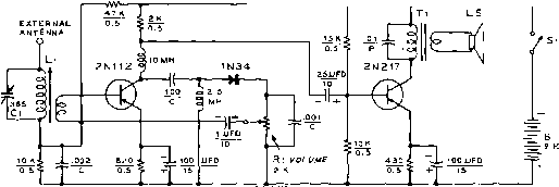 Figure 5 SCHEMATIC OF TRANSISTOR BROADCAST RECEIVER в-9-vo;t transistor battery. RCA YS-300 Ci-365 lififd. Lafayette Radio Co. MS-214, or Allied Radio Co. 6IH-009 Li-Transistor Loopsiick coil. Lafayette Radio Co. MS-66 L5-3 loudspeaker, 12ohm voice coil. Lafayette Radio Co. SK-39 Ti-500 ohm pri., 12 ohm sec. Transistor transformer. Thordarson TR-18 HANDBOOK Circuitry 533 of building and operating their own receiving and transmitting equipment. The Transceiver A popular item of equipment on five meters during the late thirties, the transceiver is making a comeback today complete with modern tubes and circuitry. In brief, the transceiver is a packaged radio station combining the elements of the receiver and transmitter into a single unit having a common power supply and audio system. The present trend toward compact equipment and the continued growth of single sideband techniques combine naturally with the space-saving economies of the transceiver. Various transceiver circuits for the higher frequency amateur bands are shown in this chapter. The experimenter can start from these simple circuits and using modern miniature tubes and components can design and build his complete station in a cabinet no larger than a pre-war receiver. 27-1 Circuitry and Components It is the practice of the editors of this Handbook to place as much usable information in the schematic illustration as possible- In order to simplify the drawing the component nomenclature of figure 1 is used in all the following construction chapters. The electrical value of many small circuit components such as resistors and capacitors is often indicated by a series of colored bands or spots placed on the body of the component. Several color codes have been used in the past, and are being used in modified form in the present to indicate component values. The most important of these color codes are Illustrated in figure 2. Other radio components such as power transformers, i-f transformers, chokes, etc. have their leads color-coded for easy identification as tabulated in figure 3- 27-2 A Simple Transistorized Portable B-C Receiver Illustrated in figures 4, 5, and 6 is an easy to construct two transistor portable broadcast receiver that is an excellent circuit for the beginner to build. The receiver covers the range of 500 kc. to 1500 kc. and needs no external antenna when used close to a high power broadcasting station. An external antenna may be added for more distant reception. The receiver is powered from a single 9-volt miniature transistor battery and delivers good speaker volume, yet draws a minimum of current permitting good battery life. Circuit Operation of the receiver may Description be understood by referring to the schematic diagram of figure 5- The tuned circuit Li-G resonates at the frequency of the broadcasting station. A portion of the r-f energy is applied to the base of the 2NI12 p-n-p type transistor. A tapped Figure 6 INTERIOR VIEW OF TRANSISTOR RECEIVER The speaker and output transformer are mounted at the left of the Ma-sonite chassis. Top, center is the loopstick r-f coil, and directly to the right is the 10 millihenry r-f choke in the collector lead of the 2NII2 transistor. Battery is at lower right. 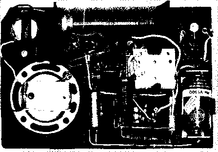 winding is placed on coil Li to achieve an impedance match to the low base impedance of the transistor. Emitter bias is used on this stage, and the amplified signal is capacity-coupled from the collector circuit to a 1N34 diode rectifier. The rectifier audio signal is recovered across the 2K diode load resistor, which takes the form of the audio volume control of the receiver. The diode operates in an untuned circuit, the selectivity of the receiver being determined by the tuned circuit in the r-f amplifier stage. The audio signal taken from the arm of the volume control (Ri) is applied to the base of the 2N112 r-f amplifier which functions simultaneously as an audio amplifier stage- The amplified audio signal is recovered across the 2K collector load resistor of the 2NI12, and is capacitively coupled to the base of a 2N217 p-n-p audio transistor. This stage is base and emitter biased, having the output transformer in the collector circuit. Optimum collector load for the 2N217 is approximately 500 ohms, and the 2N217 develops a maximum audio signal of 75 milliwatts at this load impedance. Transformer Ti matches the transistor circuit to the 12 ohm miniature loudspeaker. The receiver draws a maximum signal current of 11 milliamperes from the 9-volt battery supply. Receiver The Complete receiver is Construction mounted upon a thin Maso-nite board measuring л 4% in size. The board fits within a small plastic box having a hinged lid and handle. The dimensions of the box are 71/2 x 5 x 1 exclusive of the handle. Placement of the major components upon the board may be seen in figure 6. The loopstick antenna coil is mounted to the top center portion of the board so that it fits directly under the handle of the box. Slightly below and to the right of the coil is the tuning capacitor, С The midget speaker is mounted in a cut-out in the board at the lower left corner with the output transformer Ti directly above it. The volume control Rl is placed directly below the tuning capacitor. The battery clip for the 9-volt cell is placed at the lower right corner of the board. A three terminal phenolic strip is attached to the board above the battery clip. The leads of the 2NI12 transistor are soldered to this strip. Before the components are mounted on the board, it is placed within the plastic box and used as a drilling template for the box. A drill-press and fly-cutter may be employed to cut the speaker hole in both the board and the box. The plastic box should be drilled slowly to prevent excessive heat generation and consequent melting of the material. 4.0 TO 5.0 KC WIDE AT -b DB DOWN PLACE CARRIER HERE OR HERE 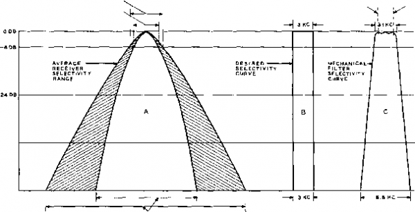 -42 DB 15 TO 30 KC WIDE AT -eo DB DOWN Figure 7 BANDWIDTH CURVES OF VARIOUS l-F SYSTEMS Bandwidth curves showing: A-Selectivity range of most medium-priced single-conversion receivers with crystal filter out of circuit; В-Ideal selectivity curve for voice reception; and С-Selectivity curve of a 455 kc. mechanical filter with a 3.1 kilocycle bandwidth. The 2N217 transistor is mounted upon a second three terminal phenolic strip placed between the tuning capacitor and the loud speaker. Use of a composition-type chassis precludes the employment of the chassis as a common ground. A simple bare copper wire is therefore used as a common ground return. This lead is actually the B-plus Bus, shown in figure 5. The lead runs from the positive terminal of the battery clip, along the lower edge of the chassis then up to the ground terminal of the loopstick coil, Li. All components that normally ground to the metal chassis in a conventional assembly are attached to this bus. Be sure to observe the polarity of the electrolytic capacitors and the dry cell. Improper connection of these components can damage the transistors or other parts of the circuit. The transistors are the last items to be connected into the assembly. Since the transistors are heat sensitive, it is necessary to protect them during the soldering operation. Grasp the transistor lead to be soldered with a long-nose pliers between the body of the transistor and the end of the lead. The thermal capacity of the metal pliers will act as a heat sink, preventing the heat of the iron from damaging the transistor. Be sure to hold the pliers in place until the completed joint has had time to cool. When all wiring is completed and checked, the 9-volt battery can be inserted in the clip (observe polarity!) and the set can be turned on by means of switch Si. A 0-100 miiliampere d-c meter placed temporarily across the open contacts of switch Si can be used to check the transistor operating current. The receiver should play immediately upon closing Sl as the transistors have no warm-up time. If no external antenna is used, the receiver should be moved about to orient the loopstick coil Ll for best pickup of each individual broadcast station- Adjacent channel interference can often be eliminated by careful rotation of the set to null out the offending signal. Ample loudspeaker volume will be obtained from local stations without the use of an external antenna. Figure 8 455 KC. MECHANICAL FILTER ADAPTER Enjoy optimum selectivity and performance from your present receiver by plugging in this simple adapter that replaces the first i-f amplifier tube. The two 6BJ6 tubes are at opposite ends of the chassis with the mechanical filter between them. Adapter plug to fit i-f tube socket is shown in foreground. 27-3 A 455 Kc. Mechanical Filter Adapter Enjoy modern-style selectivity and performance with your present receiver by plugging in this simple mechanical filter .adapter that replaces the first i-f tube! Many modern medium-priced and older high priced communications receivers now in general use are convenient to operate. The receivers have good frequency stability and adequate sensitivity, but lack sufficient skirt selectivity to reject strong signals that are only a few kilocycles higher or lower in frequency from a desired signal. The shaded area of curve A, figure 7 shows the typical selectivity characteristic of popular medium-priced communications receivers. Although the nose of this curve is usually only a few kilocycles wide, the skirt selectivity 60 decibels down from the peak may be from 15 to 30 kilocycles broad! Small wonder that strong local signals a few kilocycles up the band from the station you are trying to copy may sometimes paralyze your receiver. It is possible to add a new order of selectivity to your present set by constructing this mechanical filter adapter unit, that is substi- 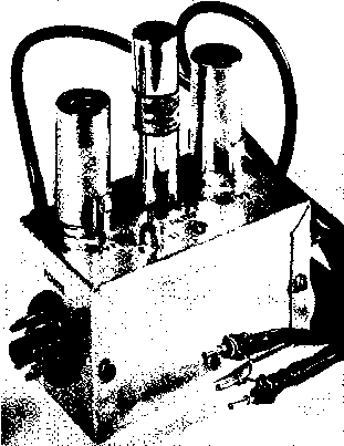 INPUT CABLE OUTPUT CABLE 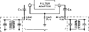 1ST IF TRANS. l-F TUBE SOCKET TERMINALS 2ND l-F TRANS. Figure 9 CONNECTIONS BETWEEN MECHANICAL FILTER, ADAPTER AND RECEIVER Adapter makes connections to first i-f socket of receiver. Power may also be obtained from the receiver. tuted for the first 455 kc. intermediate frequency amplifier tube, without making any under-chassis changes in the receiver. Simply connect the adapter to a power source (which may be your receiver), remove the first i-f amplifier tube, and insert two short coaxial cables into the empty tube socket, as shown in figure 9. These cables carry the i-f signal to and from the adapter, which are then tucked away in an unoccupied corner of your receiver or speaker cabinet. Selectivity There are two systems gen- Considerations erally used to obtain a bandpass characteristic that approaches the ideal communications selectivity curve for voice modulated signals shown at В in figure 7. One system utilizes a package fil- ter such as the mechanical filter or a crystal lattice filter. The second system utilizes a string of high Q tuned circuits in the i-f amplifier to achieve the desired passband. This latter system can be space consuming, difficult to adjust, and expensive if quality components are employed. On the other hand, the mechanical filter is very compact. It is readily available in a variety of bandwidths, has an excellent selectivity curve, and is roughly equivalent in cost to other systems having comparable selectivity. Curve С of figure 7 illustrates the selectivity curve of the 3.1 kilocycle Collins mechanical filter which is suitable for A-M phone and single sideband reception. Circuit The complete circuit of the Description mechanical filter adapter is shown in figure 10. Two 6BJ6 pentode tubes are employed in the ciircuit to compensate for the insertion loss of the filter. The adapter picks up the 455 kc. signal from the control grid pin of the receivers first i-f amplifier tube socket through coupling capacitor, G. The signal passes through a coaxial line to the grid of the 6BJ6 amplifier tube, Vi. The plate circuit of Vi is capacity coupled to the input terminals of the mechanical filter to keep plate current from flowing through the filter coil. A much wider signal voltage range can be handled by the filter without 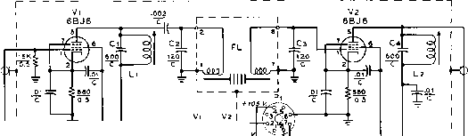 *--f-ios-iso и JSHIELP SHJ£LO i 10 ) TO l-F ПтивЕ socket! GRIDPIN PLATE PIN ► TO GND. PIN, l-F TUBE SOCKET Figure 10 SCHEMATIC OF MECHANICAL FILTER ADAPTER Cl, C<-600 fififd. ceramic (270- and 330 fififd. in parallel) С г, Сз-720 lififd. ceramic Cs, C -10 ii/ifd. tubular ceramic (Aerovox CI-1) FL-4SS kc. mechanical filter (3.1 kc. bandwidth) (Collins 4SSJ-31) Ll, Ll-200 microhenry slug-tuned loop stick coil (Superex VL, or J. W. Miller 6300) Pi-Male octal plug with retaining ring (Amphenol 86-PMB) Rl-18K, 10 watt. Place between pins 4 and 8 of PI socket for plate supply greater than 130 volts. Use jumper for 130 volts or less (see text). Ri is screen voltage dropping rtsistor. HANDBOOK Mechanical Filter 537 v2, 6bj6 Lp.C 2,1-4 TO P I N 1 Vi {6Bj6) SOCKET
то GRI D PIN l-F TUBE SOCKET Figure 11 OPTIONAL A-V-C CONNECTIONS FOR THE ADAPTER overloading when no plate current flows through the input coil. Both filter coils are tuned to resonance at the intermediate frequency by fixed capacitors Cs and Сз. The output terminals of the mechanical filter are connected directly to the input circuit of the second 6BJ6 tube. The output signal from this tube is again capacitively coupled back into the plate circuit of the first i-f stage of the receiver through a second coaxial line and coupling capacitor The 455 kc. tuned circuits connected to the plate of Vi and V: are composed of loopstick -type coils Li and Ls, shunted by fixed capacitors Ci and Ct. The input and output coaxial cables are 16-inch lengths of RG-58/U line. This cable forms a 40 ju,/afd. ground leg of a capacitor voltage divider (C5 being the other leg) that reduces the signal voltage applied to Vi to about one-quarter of the voltage developed across the secondary of the first i-f transformer of the receiver. The overall signal amplification of the adapter has been held down to a few decibels more than the 10 db insertion loss of the filter through the use of small input and output coupling capacitors and large cathode bias resistors in both amplifier stages. This is suitable for receivers having two or more i-f amplifier stages, but additional gain from the adapter may be obtained by reducing the value of one or both cathode resistors to 270 ohms. This may be desirable when the adapter is operated with a receiver having only one i-f amplifier stage. Power is brought into the adapter unit through an eight-pin male plug. Connections to this plug are made so that the plug may be inserted into the NBFM adapter socket on certain National receiver models- Many communications receivers have an accessory power socket on the rear of the chassis from which power may be obtained. Adapter requirements are 6.3 volts at О.З amperes, and 105-250 volts at 10 milliamperes. This is little more than the power requirements of the i-f tube replaced by the adapter. A 250-volt supply source requires that an 18K, 12-watt screen voltage dropping resistor (Ri) be connected between pins 4 and 8 of the power plug receptacle. When the d-c supply is 130-volts or less, a jumper may be placed directly between pins 4 and 8 (see figure 10). A method of applying automatic volume control voltage from the receiver to the second amplifier stage in the adapter is shown in figure 11. This modification is mainly useful when the adapter is connected to a receiver that has few a-v-c controlled stages. The automatic volume control voltage is taken from the control grid pin of the i-f amplifier tube socket through a simple R-C filter and is applied to the control grid of through the output coil of the mechanical filter. 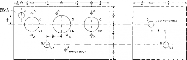 2- X 4 MINIBOX (BUD CU-3003 OR EQUIVALENT) Figure 12 CHASSIS DRILLING TEMPLATE FOR ADAPTER A; #32 diiU, B: 9/32 МП, С; 5/8 dinmeter socket punch, D: 3/4 diameter socket punch Con$trucHon The adapter is constructed ef Ae Adapter on an aluminum box measuring 214 X 214 X 4 , a good compromise size that is compact, yet not too small for easy wiring. The primary design and construction consideration of this adapter is to completely isolate the input and output circuits. Any stray coupling can cause signal leakage around the filter unit, thus imparing its effectiveness. The construction shown allows maximum isolation, yet permits simplicity of construction. A drilling template for the box is given in figure 12, and the placement of the major components may be seen in figures 8, 13, and 14. Note that the input and output circuits are isolated within the box by a shield passing across the center of the filter socket. After drilling and punching all holes, the tube and mechanical filter sockets, power plug, and rubber grommets may be assembled. Place solder lugs under all socket retaining bolts for ground connections- Before any wiring is done a 3 x 3 piece of perforated alumimmi {Reynolds Do-it-yourself aluminum, available at large hardware stores) is formed into the shield shown in figures 13 and 14. A Ys flange is bent along all edges of this shield except where it crosses the center of the 9-pin filter socket. A small notch is cut in the shield next to the socket to pass the heater and plate power leads to the socket. The shield passes across the filter socket between pins 3 and 4, and 8 and 9, then is bolted to a soldering lug that has been soldered to pin 1 of the filter socket. The flange is also bolted to the top of the box directly above coil L2, and two self-tapping sheet metal screws are driven into the side flanges of the shield when the other half of the box is assembled. Cable Constructing the two i-f tube Assembly socket cables takes litde time if the assembly shown in figure 15 is followed. First, cut two lengths of RG-58/U coaxial cable 17 inches long and remove 1V2 inches of the vinyl cover on one end of each piece. Slide the braided outer shield back over the outer cover and trim the insulation and center conductor so that V2 inch protrudes beyond the shield. Next cut the insulation to expose 14 inch of the center conductor and trim one lead of the coupling capacitor Cs soldering it to the center conductor with a 14 inch overlap. Cut narrow strips of plastic insulating tape and wrap them around this joint up to the body diameter of the capacitor as shown in figure 15. Finally, slide the braided shield over the capacitor, pull it tight and wrap a short length of tinned copper wire twice around the middle of the capacitor. Solder the wire to the shield and trim off the excess shielding. The tinned wires from each cable are then soldered to a pin taken from an octal tube base, making a plug-in ground connection as shown in figure 8. Similar tube base pins are soldered to the other leads, and rhe excess lead trimmed off. The exposed cable shield is then wrapped with plastic tape. If the receiver has a 7-pin miniature tube in the first i-f amplifier stage, short lengths of #18 tinned wire may be used for the plug-in pins on the cables, or the capacitors and ground lead may be soldered to a special 7-pin miniature male adapter plug (Vector P-7}. Adapter For easy parts assembly, the filter Wiring shield may be temporarily removed, and replaced when wiring is completed. Heater, screen and plate power wires are installed first, keeping all such leads close to the box wherever possible to minimize 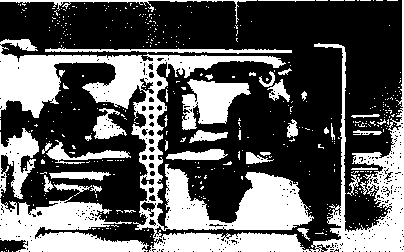 Figure 13 UNDERCHASSiS VIEW OF THE ADAPTER Slug-tuned coil Lj is ai left, below the second stage 6 В J 6 socket. Screen bypass capacitor is placed across socket. Capacitors Сг and Сз may be seen on each side of the center shield. Coil Li is at right of shield. Input cable is at far right. Output cable passes through rear wall of chassis at left. Power leads pass through center of shield. HANDBOOK Mechanical Filter 539 stray signal pickup. The smaller components are now soldered in place, after which the coaxial cable input and output leads are connected. About Ys inch of the outer vinyl jacket is removed from the cables and the shield braid is twisted into a single conductor. The cable ends are brought into the box through rubber grommets. The twisted cable shield is soldered to a nearby ground lug and the center conductor is soldered to the correct tube socket pin. Finally coils Li and L2 and their associated capacitors are placed in position and wired into the circuit. Alignment The adapter is connected to of the Adapter to the communications receiver as previously described, following a wiring and power check to ensure that the correct voltages are applied to the various tube elements. The receiver should then be tuned to the center of a strong, steady local signal. If the receiver has an S-meter, the a-v-c should be left on. The slugs of coils Ll and L: are now tuned for maximum carrier strength reading on the S-meter. If the receiver has no S-meter, a modulated signal from a test oscillator must be used in conjunction with a vacuum tube voltmeter placed across the audio output circuit of the receiver. Tuning adjustments on the first and second i-f transformers in the receiver are also recommended for maximum output of the adapter. POLYETHYLENE INNER INSULATION 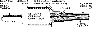 BRAID SHIELD OF COAXIAL LINE PULLED OVER JOINT AND CAPACITOR, SOLDER TO GROUND WIRE Figure 15 CROSS-SECTION VIEW OF SIGNAL CABLES Receiver Tuning Techniques A somewhat different tuning technique should be used for tuning A-M and single sideband signals on a receiver following installation of the mechanical filter adapter. Modulated signals with carrier should be tuned in so that the carrier is placed on one edge, rather than in the center of the i-f passband (figure 7). Only one sideband of an A-M signal will be heard at one time, and the receiver tuning may be shifted so that the sideband on which a heterodyne is present may be pushed off the edge of the bandpass curve of the i-f system. When receiving single sideband or c-w signals the beat frequency oscillator of the receiver is turned on and adjusted so that the frequency of the b-f-o is near one edge of the Figure 14 OBLIQUE VIEW OF ADAPTER CHASSIS Coil Ll is at left near power plug, with coil Li mounted horizontally at right. Note Ct and Cj are placed directly across pins of mechanical crystal socket. 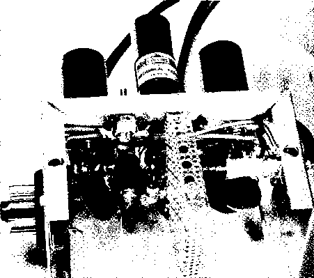  Figure 16 FRONT VIEW OF AMATEUR BAND RECEIVER 6-bantl receive/ covers 80-6 meters, using TV turret for front end. Mecfianicat filters provide optimum selectivity filter passband. The proper pitch control setting may be determined by tuning the receiver across a carrier while adjusting the pitch control so that a beat note on only one side of zero beat is heard. After marking this setting of the pitch control, again turn it so the test signal on only the other side of zero beat is heard-Mark this setting, then try tuning in a single sideband signal. If intelligible speech cannot be heard, shift the b-f-o pitch control to the other setting. Small adjustments of the pitch control and the tuning of the receiver will produce the correct voice tones. For best reception, the audio control of the receiver should be fully advanced, and only enough r-f gain used to produce a readable signal. Volume is therefore controlled by the r-f gain control. For optimum c-w reception, the 0.5 kc. mechanical filter may be used. No changes need be made to the adapter when filters are changed. 27-4 A High Performance Amateur Band Receiver This receiver was designed for outstanding performance on the 80, 40, 20, 15, 10, and 6 meter amateur bands. It incorporates many up-to-date features such as mechanical filters for Optimum selectivity, double conversion for freedom from images, and a novel r-f assembly for mechanical stability and good operating efficiency on the higher frequencies. The receiver uses 12 tubes, plus a selenium rectifier power supply. The complete r-f assembly is designed about a television turret tuner having positions for 12 separate bands. The rugged construction and excellence of the self-wiping contacts of the TV tuner add greatly to the overall stability of the receiver. Complete dial calibration and an S-meter provide maximum tuning simplicity and logging ease. Because of the snap-in coil strips of the tuner it is possible to provide coils to tune any narrow segment of the shortwave range between 3-5 megacycles and 75 megacycles. For example, coils can be wound to cover the 13, 19, 21, 31, and 49 meter international shortwave broadcast bands if desired. Panel control of the selectivity allows instant selection of the optimum passband for either voice or c-w reception. The receiver is entirely self-contained except for an external speaker, Circulf- The High Performance Ama- Descriphon teur Band Receiver is a double conversion superhetrodyne (figure 17). A modified TV turret tuner is employed to cover six amateur bands. The turret 12-BAND TUNER PACKAGE R-F MIX/OSC MIXER b07aj eje imjCCeBAT MECH FILTER is 2150 KC. XTAL MECH. FILTER 3K - 
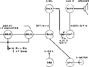 6Bje VOLTAGE REGULATOR A-V-C BRIDGE Figure 17 BLOCK DIAGRAM OF DE-LUXE AMATEUR COMMUNICATION RECEIVER 1 ... 50 51 52 53 54 55 56 ... 80 |
|||||||||||||||||
|
© 2026 AutoElektrix.ru
Частичное копирование материалов разрешено при условии активной ссылки |