 |
 |
 |
| Главная Журналы Популярное Audi - почему их так назвали? Как появилась марка Bmw? Откуда появился Lexus? Достижения и устремления Mercedes-Benz Первые модели Chevrolet Электромобиль Nissan Leaf |
Главная » Журналы » Simple coaxial reflectometer 1 ... 51 52 53 54 55 56 57 ... 80 Amateur Band Receiver 541 employs a 6BQ7A cascode r-f amplifier and a 6J6 mixer-oscillator. All r-f tuned circuits are changed as the tuner is switched from channel to channel. The intermediate frequency output of the tuner is 1695 kc. A 6BA7 pentagrid mixer tube converts the first intermediate frequency to the second i-f channel, which is 455 kc. To obtain a high order of stability, the 6BA7 conversion oscillator is crystal controlled at 2150 kc. Switch Sl in the output circuit of the 6BA7 mixer stage permits the selection of one of the two mechanical filters- In this particular receiver, a б kc- and a 3.1 kc. filter were used for broad and sharp phone reception. Three stages of 455 kc. amplification follow the mechanical filter. The gain of these stages is adjustable, permitting the overall receiver gain to be set at a reasonable value. Too much i-f gain, will make the receiver noisy and subject to overloading effects on strong signals. Too little i-f gain will make the receiver seem insensitive. The i-f gain is controlled by potentiometer Rl and also by the value of the cathode resistors in the second and third i-f stages. In order to prevent clipping of the excellent flat-top response of the 6 kc. mechanical filter, small coupling capacitors are placed across the top of the i-f transformer coils to widen the nose response of the circuits. The skirt selectivity of the i-f strip is determined by the passband of the mechanical filter and not by the transformer response. To conserve filament power, 150 miiliampere 6BJ6 tubes are employed in the i-f amplifier. A 6AL5 dual diode is used as a second detector and a-v-c rectifier. Automatic volume control voltage is applied to the first two i-f stages, and a small portion of the a-v-c voltage is applied to the 6BQ7A r-f amplifier and 6BA7 mixer. The a-v-c circuit is rendered inoperative for c-w and SSB operation by segment D of switch S:. A simple delayed a-v-c system is used to allow best reception of weak signals- Potentiometer Ra sets the delay voltage applied to the cathode of the 6AL5 a-v-c diode. A second 6AL5 serves as a noise limiter. The threshold value of limiting is set by control R2, and the noise limiter may be removed from the circuit by switch S.i, The audio output of the detector passes through volume control R* and is further ampUfied by one triode section of a 12AT7 followed by a 6AK6 power amplifier stage. The second section of the 12AT? functions as the beat frequency oscillator. The frequency of the b-f-o is controlled from the panel by variable capacitor Cs. The S-meter circuit consists of a single vacuum tube voltmeter using a 12AU7 dual triode in a bridge circuit. The bridge is balanced by potentiometer Rb, and the meter sensitivity is set by control Ri. Automatic volume control voltage applied to one grid of the 12AU7 upsets the balance of the bridge and causes a TV-TUNER Г A4T. j 1 6BQ7A = TUNER TRIMMER 5 S Tc cT 01 с ® то A-v-c 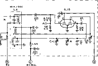 l-F OUTPUT Figure 18A FRONT-END OF AMATEUR BAND RECEIVER CONVERTED TV-TUNER FORMS Several forms of replacement TV-tuners may be purchased from large radio stores. Shown above is typical cascode tuner to be used in this receiver. Check your tuner for circuitry before you modify it, I-f output frequency is unimportant, since i-f components of tuner are removed. Tuner trimmers permit minor adiustments to be made to alignment of r-f stages. A-Oscillator-mixer excitation meosuring point on tuner CiA-B-C-75 tiiitd. per section. All-Star Products Co., Defiance. Ohio. Model C3. Cl-ro liiifd. ceramic. Centralab S27B Cs-15 Bad LC-)64). (Mounted otop chassis orter photographs were taken). Li-Lj-See Figure 27 for coil data 6AL5 NOTES : 1 -х- see FILTEn INSTRUCTION SHEET FOR CAPACITOR SPECIFICATIONS. Z-ALL RESISTORS 1-WATT UNLESS OTHERWISE NOTED. A-N-L y.-Z1S0KC. SEE Fie, IB A S2D -Л MAN HHi- .0 5 p о t< amJ 115v. j\J ъ i>- b+hi 140 v. О О о SRi SR2 CAIN l-F GAIN Д^ ADJUST 1 К b+HI hov. -AV- за к 3k? m/Sjo cw 1 1 6AK6 AUDIO avc bias delay -AV- 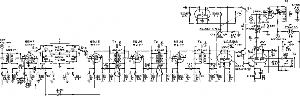 270 к O.s FIG. 11 1.5k 10  2.2 M i Сз,!5 adjust a-f-o icw :e, 10 ST ZERO (1 12AU7 g , S-METER о О о :01 с r7, 500 Figure 18В SCHEMATIC OF AMATEUR BAND RECEIVER ГАе frant-end circuit is shown in Figure 18A. The tuning capacitors placed across the input and output circuits of the mechanical filters are determined by the choice of filter. See filter specification sheet. Type F455C filters were used in this recerver. M-0-1 d-c milliammeter, 1-inch diameter SiA-B-DPDT rotary switch. Centralab PA-2001 decks, with Centralab PA-302 Index assembly StA-B-C-D-4 pole, 3 position switch. Centralab PA-1013 T-1500 fee. l-t transfornw, J. W. Miller Co. 512-W1. Remove iurra tram primary and secondary ta permit resanonce of 7695 kc. T,-Tf-4S5 kc. i-f transformer. J. W. Miller Co. 12-07, or equjvofenf Tr-455 Ire. diode tronsformer. J. W. Miller Co. I2-C2, or e(iiivoienf 7-455 fee. BFO transformer. J. W. Miller Co. 7I2-C5, or equivalent Ts-750-0-750 volU at 100 ma. UTC S-5 7 Ts-70 fC pri., 4 ohm sec., Stancor A-3B79 T;-6.3 volts, 3 amp., Stancor P-6466  adjust sens. HANDBOOK Amateur Band Receiver 543 reading on the 0-1 d-c milliammeter connected between the plates of the 12AU7 triodes. The selenium rectifier power supply delivers 140 volts at the ireceiver current drain of 65 milliamperes. The low plate voltage and small power consumption of the receiver result in a very low degree of thermal drift. If desired, the selenium supply may be replaced with a more conventional supply using a 5Y3-GT rectifier tube. Plate voltage to the receiver should be held below 160 volts. Plate voltage to the 6j6 oscillator section and the 12AU7 S-meter tube is regulated by an OB2 gas regulator. Plate voltage is removed from the r-f and audio stages when the receiver is in standby condition. All oscillators are left running continuously to reduce initial warmup drift. Receiver The receiver is built upon a plated Layout steel chassis measuring 8 x 15 x 21/2 . Panel height is 8 . To achieve maximum rigidity, the panel is braced to the chassis with two steel angle brackets visible in figure 19. The tuning dial is centered on the panel, and the three gang tuning capacitor is behind the dial, on the center-line of the chassis. Directly to the left of the tuning capacitor is a 3V x 5 cut-out in the chassis-The TV tuner is placed in this cut-out, held in place by two 3 angle brackets cut from aluminum stock- Height of the tuner above the chassis is determined by the shaft of the tuner which must pass through the bushing drilled in the lower left corner of the dial escutcheon. Likewise, the placement of the three gang tuning capacitor Ci is determined by the shaft height of the main dial bushing. G is therefore mounted above the chassis by means of long 6-32 bolts and steel spacers- Placement of the major components may be seen in figures 19 and 20- The two mechanical filters are mounted to the left of the tuner, directly behind the 6BA7 mixer tube and the 1695 kc. i-f transformer, Ti. The filter selection switch Sl is mounted below chassis so that the switch segments fall over the filter terminals. This switch is made up from a switch kit, and is mounted in place by means of two brackets cut from soft aluminum. One bracket holds the front panel bushing of the switch, and the other is placed just forward of section SiB and holds the two fixed shafts of the switch. A hole is cut in the center of the bracket to clear the rotary shaft of the switch. This bracket also serves as a shield isolating the output circuits of the mechanical filter from the input circuits. The particular switch used is highly recommended, and it is suggested that no substitution be made. It is imperative that the drive shaft of the switch be metal, and that it is securely grounded. Some switches have fibre drive shafts, or metal shafts held in position with a cotter pin. Fibre drive shafts permit signal leakage along the shaft, deteriorating filter performance, and the cotter pin-type switch does not insure the shaft is securely grounded which is mandatory, when the metal shaft-type switch is used. The three intermediate frequency stages are spaced along the back of the chassis. At the right rear are the 6AK6 audio stage, the volt- Figure 19 TOP VIEW OF AMATEUR COMMUNICATION RECEIVER Atechanrcof filters ore of left with three stage I-f amplifier along rear ot cliassis. The TV tuner Is mounted In citassis cutout to the left of mofit taning capacitor. Power supply and audio section occupy right-hand section of steel chassis. Six channels ot tuner are used to cover the amateur bands between 80-and 6-meters. Six spare channels may be used to cover Shortwave broad-cost bands, or portions at 100 Mc. region. 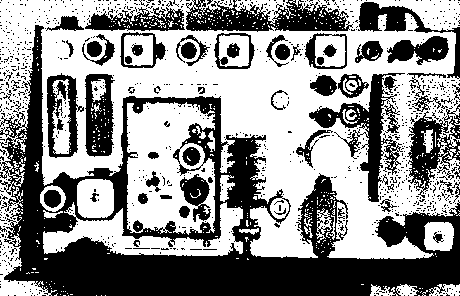 age regulator tube, and the 12AU7 S-meter tube. In front of the last i-f transformer can are the two 6AL5 tubes and potentiometers Re and Rj. At the right end of the chassis is the power transformer, and between it and the panel is the b-f-o transformer and the 12AT7 au-dio/b-f-o tube. Between the power transformer and the three gang tuning capacitor are the power supply filter capacitor and the auxiliary filament transformer. The i-f gain control potentiometer Rl is placed between the filament transformer and the main tuning capacitor. Placement of the smaller components below the chassis may be seen in figure 20. The TV turret and mechanical filter switch are at the right of the chassis, with the audio output transformer mounted to the back wall of the chassis near the turret. The filter choke for the power supply is mounted to the left side wall of the chassis, with the two selenium rectifiers in front of it. The 10 watt dropping resistor for the regulator tube is mounted to the chassis beween the filter choke and the rear tube sockets. Receiver The receiver should be built Construction in two parts to simplify construction. The power supply, audio and 455 kc. i-f sections are built first, and the receiver is placed in operating condition up to the 1695 kc. i-f channel. The TV tuner is then modified, using the rest of the receiver for alignment and adjustment tests. All major components should be marked in position on the paper wrapper of the chassis which is then drilled and punched. All major components with the exception of the TV turret are mounted in place. The ground connections at each tube socket are made first, then the filament leads are wired in position. Use #14 insulated wire for the filament leads, as the current drain is quite high. The power supply should be wired first and tested. It should deliver approximately 140 volts across a 2000 ohm, 10 watt resistor used as a temporary dummy load. When the power supply section is completed, the audio stages, b-f-o, S-meter, second detector, and noise limiter stages can be wired. Operation of the audio system may be checked by injecting a small audio signal on pin #2 of the 12AT7 stage and checking the volume of the tone in the loud speaker. The next step is to wire the three i-f amplifiers and the a-v-c circuit. Five terminal phenolic tie-point strips are mounted in front of each i-f tube socket. The a-v-c, cathode bias, and screen dropping resistors are mounted between the socket pins and the terminals of the strip. The ceramic bypass capacitors are soldered directly between socket pins with the shortest possible leads. All interconnecting wiring is done between the terminal strips-After the i-f strip has been wired up to the arm of switch Si, segment B, the amplifier may be tested. Pin #1 of the first 6BJ6 i-f tube is temporarily returned to the a-v-c bus by placing a 100 К resistor across the output pins of the mechanical filter socket. Switch Si is adjusted to place the resistor in the circuit. 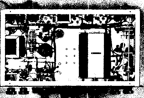 Figure 20 UNDER-CHASSIS VIEW OF AMATEUR BAND RECEIVER To the left of the chassis are the selenium rectifiers and the filter choke. At the extreme right is the mechanical filter selector switch ntounted on two aluminum brackets. The controls along the panel are (left to right): BFO, AUDIO GAIN, MAN-AM-CW, tuning control, TV turret switch, R-F GAIN, and filter selector switch. Output transformer Is mounted to bock of chassis. HANDBOOK Amateur Band Receiver 545 A signal generator having a tone modulated 455 kc. signal is attached to the input grid of the 6BJ6 tube, and an a-c voltmeter is connected across the speaker terminals. To insure that the i-f system is aligned at the center of the filter passband it is imperative that the alignment frequency be very close to 455.0 kc. The use of a BC-221 or equivalent signal generator is recommended. As the transformers are brought into alignment the input signal to the i-f strip should be decreased. A vacuum tube voltmeter may be employed to measure the negative voltage developed on the a-v-c bus. A maximum voltage of about ~8 volts is developed with a strong input signal to the i-f strip. Overall gain is controlled by the setting of Rl when switch Sa is placed in the A-M position. After i-f alignment has been completed, the 100 К input resistor should be removed from the filter socket and the 6BA7 mixer stage wired. The capacitors connected between pins 1 and 2 and ground of the 6BA7 socket determine the level of excitation to the 2150 kc. crystal. If difficulty is encountered in obtaining consistent oscillation, the value of one or both of these capacitors may be altered until reliable oscillation is obtained. Operation of the crystal oscillator may be monitored with a nearby receiver tuned to the crystal frequency. When the oscillator is working properly, a 1695 kc. tone modulated signal should be coupled through a 0.01 jafd. blocking capacitor to the hot end of the primary winding of transformer T. This transformer is adjusted for maximum output signal. The receiver is now ready for tuner installation. Tuner The tuner used in this re- Modification ceiver is a Standard Coil Co. replacement type unit using a 6BQ7A cascode r-f amplifier and a 6J6 mixer stage. Several different variations of this tuner can be purchased at nominal prices through large wholesale outlet stores. The tuner has snap-in coil strips for 12 TV channels, and may have either a 21 Mc. or 42 Mc. i-f output range. Several simple changes must be made to the tuner for use in this receiver. The i-f output coil and the cascode neutralizing circuit must be removed. The best thing to do is to remove all the clip-in coik and trace out the tuner circuit, and then compare it with the circuit shown in figure 18A. Cathode bias must be added to the first section of the cascode and several of the resistors in the tuner must be changed. Rewire the tuner according to the circuit of figure 18A. Note that regulated voltage is applied to the oscillator section of the 6J6 and that a-v-c voltage is applied to the first section of the 6BQ7A. The main tuning capacitor ClA-B-C is connected to the appropriate points in the tuner by three short leads. A )i-inch coil is drilled in the rear of the FIGURE 21 - coil table for amateur band receiver
tuner case to permit the coaxial lead from the antenna receptacle to enter the tuner. The tuner is now ready to be mounted in the receiver. Tuner Coil The tuner coils should be Modification removed from their snap-in holders. Notice that the r-f coils have five terminals and that the mixer-oscillator coils have six terminals. All coil forms and windings are removed from the clip-in assemblies and may be discarded. The new coils for all bands are to be wound on lengths of 14-inch diameter polystyrene rod, cut to fit into the assembly clamps. For this particular tuner, the r-f coil forms are lYa long and the oscillator mixer coil forms are 1 13/16 long. The ends of the forms are tapered slightly with a file so that they fit into the slotted ends of the assembly clamp. After each set of coils is completed the frequency band notation is marked on the unit for future identification. Complete coil data is given in figure 21 and a complete set of coils is shown in figure 22. Start with the ten meter coils, as they have few turns and are easy to wind. Make the r-f stage coil first. The windings may be tem-         porarily held in place with small piece of cellophane tape until the coil form is cemented in the assembly clamp with Duco cement. The coil leads are then cleaned and soldered to the corresponding terminals. After the shunt capacity is added, the natural resonance of the winding should be checked against the value given in figure 21. The coil should be suspended in the clear and checked with a grid--dip oscillator. Turn spacing may be varied to produce the correct resonance point. The mixer-oscillator coil is wound next. The two tuned windings are placed at the ends of the form and the oscillator plate winding is placed between them, positioned close to the grid winding as illustrated in figure 22. The coil windings may be held in position with a temporary piece of cellophane tape. This coil is adjusted in the same manner as the r-f coil. When completed, the mixer-oscillator coil may be snapped into the tuner and the receiver turned on. The oscillator operates on the low frequency side of the signal for 10 meter reception, covering the range of 26,3 Mc. to 28.0 Mc. as the receiver is tuned from 27,995 kc. to 29.7 Mc. Listen for the oscillator in a nearby receiver. The frequency range of the oscillator can be set by varying the spacing of the turns of the 6J6 oscillator coil, and also by adjustment of the oscillator trimmer capacitor C2 in the tuner. When the correct frequency range is covered the winding may be permanently held in place with a small application of Duco cement. Check the frequency range once again after you apply the cement as the frequency shifts slightly lower as the cement is applied. Make your final correction before the cement dries. The other coil windings are relatively non-critical and require no adjustments after they are completed. Once the oscillator tuning range has been set, the signal generator may be used to calibrate the main dial of the receiver. If care is used in this process, the dial calibrations can be read to an accuracy of five kilocycles or less. The oscillator injection voltage may be checked at terminal A on the tuner with a v-t-v-m. The injection range should He between two to three volts on each band, and may be controlled by varying the spacing between the Figure 22 COIL SET FOR AMATEUR BAND RECEIVER Tuner eoih are wound on y-mch polystyrene rods. R-f coils are at left, with mbcer-oscillaior coils at right. SO meter coils are at top of photo, with 6 meter coils at bottont. HANDBOOK Handie-Taikie 547 oscillator grid winding and the untuned plate winding. These adjustments may be made with the coils in the receiver by removing the bottom and side plates of the tuner. The conversion oscillator operates on the high frequency side of the signal on the 15, 20, 40, and 80 meter bands, as tabulated in figure 21. The 80 coils are made from loop-stick; -type broadcast coils. Turns are removed from these coils until the natural resonance falls at the desired frequency as shown in the table. A small value of capacitance is used across these coils since the percentage-tuning range is quite high. Receiver After the first set of coils has Adjustment been completed, the receiver may be adjusted for optimum results. A balance between r-f gain and i-f gain must be achieved. Under normal operating conditions, the residual noise picked up by the antenna system should mask out the internal noise level of the receiver. If the antenna is removed from the receiver and the internal noise level does not drop appreciably it is usually a sign that the i-f gain of the receiver is too high and the r-f gain is too low. The value of i-f gain may be controlled by the setting of Ri. Normally, there is no instability or regeneration in the i-f strip. The stability, however, is dependent to some extent upon the wiring technique you use; it may be necessary to retard the i-f gain level to prevent instability. Receiver i-f gain may be further decreased by increasing the value of the cathode resistor of the first 6BJ6 stage. I-f gain may be increased by decreasing the value of the cathode resistors of the second two i-f stages. The a-v-c bias delay potentiometer Rs should be set to provide about one volt of bias on pin # 1 of the 6AL5 a-v-c rectifier. This will retard a-v-c action on weak signals and improve the signal-to-noise ratio of threshold signals. The level of beat oscillator injection can be set by varying the setting of coupling capacitor c4. Sufficient injection should be used to provide good reception of single sideband signals. The injection level is not critical for c-w operation. Finally, the b-f-o capacitor G should be set at mid-scale and the slug of transformer Ъ adjusted until the b-f-o signal is tuned exactly to 455 kc. The response of the S-meter is controlled by the time constant in the grid of the 12AU7 meter tube. If the grid capacitor in this circuit is increased in value from .05 /xfd, to 1.0 fiid. the S-meter will respond much more slowly to changes in signal strength. The value of this capacitor can be altered to suit the users taste. Finally, various settings of the noise limiter threshold control R2 should be tried to find the best clipping level for various types of pulse-type interference. Receiver Receiver tuning is extremely Operation smooth, and the dial calibration remains as good as the original calibration. The r-f input circuits are designed for 50-100 ohm unbalanced transmission line on all amateur bands, and r-f stage resonance may be easily attained by means of the antenna trimming capacitor located within the set. For phone reception, switch S2 is set to A-M and the audio level is controlled by the audio potentiometer r4. For c-w or sideband reception Si is set to C-W and audio control Rt is fully advanced. Receiver gain is now controlled by the R-F gain potentiometer Rj. The B-F-O pitch control Cs is adjusted to place the oscillator on the edge of the filter pass-band for single signal reception of c-w signals or single sideband reception of SSB transmissions. The S-metet is operative on the A-M position of S2; S-meter sensitivity is controlled by potentiometer r7. 27-5 A Handle - Talkie for 144 Mc. The 144 Mc. band is the ideal frequency range for short-haul, portable equipment. Little power is required for local coverage, and the antenna size is moderate. Then too, this is just about the highest frequency at which filament type battery tubes will operate. Shown in the accompanying illustrations is a battery powered, crystal controlled handie-talkie designed for operation in the 2 meter region. It is especially well suited for Civil Defense work or emergency service. This unit was designed after the AN/URC-4 air-sea rescue transmitter, and is completely self-contained, including batteries. Circuit The circuit of the handie- E>e$cripHon talkie is shown in figure 24. Six quick heating filament t5e tubes are used. Two tubes are used in the transmitter portion of the transceiver, two in the receiver portion, and the remaining two in the common audio section. The transmitting portion of the unit employs a за5 dual triode and a 3A4 pentode. The first triode section of the 3A5 serves as an overtone crystal oscillator, delivering 24 Mc. energy from an 8 Mc. crystal. The crystal oscillates in series mode and sufficient regeneration is introduced in the circuit by returning the crystal circuit to a tap on the oscillator plate coil. The oscillator may be adjusted by tuning the slug of coil Li. The 24 Mc. plate circuit of the oscillator stage is capacitively coupled to a 3A4 pentode tripler stage whose plate circuit is tuned to 72 Mc. This stage is resonated by means of the slug of coil La. The 3A4, in turn, is capacitively coupled to the second section of the original 3A5 which 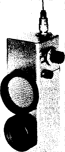 Figure 23 BATTERY POWERED HANDIE-TALKIE FOR 2 METERS Compleieiy self-containetl transceiver employs crystal controlled transmitter for greatest stability. Send-receive switch is at top right with tuning control of receiver directly below. serves as a doubler from 72 Mc. to 144 Mc. Tuning of the plate circuit is accomplished by the slug of coil Lo. Inductive coupling is used between Le and the quarter-wave whip antenna. The receiver employs a 5678 sub-miniature pentode r-f stage to provide a better signal-to-noise ratio and also to reduce spurious radiation from the super-regenerative detector. At a distance of fifty feet from the transceiver, the detector radiation is inaudible to a sensitive receiver. In the interest of economy, the 5678 can be replaced with a 959 acorn tube if miniaturization of the unit is not desired. The super-regenerative detector uses a special quench circuit which provides smooth operation yet allows the usual variable quench control to be eliminated. Values shown in the schematic are optimum, and care should be taken to keep all leads short. Capacitor Ci is the receiver tuning control and has a range of 140 Mc. to 150 Mc. If it is desired to reduce the tuning range, one or two plates can be removed from Ci and coil La readjusted accordingly. The 5676 can be replaced by a 957 acorn tube in the interest of economy. Audio output from the super-regenerative detector is passed through a simple R-C filter to suppress the quench frequencies. The first audio stage is a 1S5 pentode using contact potential grid bias. Interstage coupling is accomplished by a Centralab Couplate printed circuit incorporating the six components required at this juncture. If this item is not available, the values of resistance and capacitance shown can be substituted. The output stage consists of a 3Q4 power pentode driving a 21/-inch speaker through the output transformer Ta. For reception only one-half of the 3Q4 filament is used to conserve A and B battery drain. During transmit periods the extra audio is needed and the other half of the filament is energized. The send-receive switch SlA-B-C-D-E is a miniature ceramic rotary switch. Section A switches the antenna from the receiver to the transmitter. Secion В energizes the filaments of the receiver r-f tubes on the receive position, and energizes the microphone and the second section of the 3Q4 filament on the transmit position. Section С turns off all filaments in the off position, and section D opens the 67.5 volt battery circuit in the off position. Section E connects the loudspeaker to the audio system in the receive position of switch Si. The extreme counterclockwise position of Si is the off position. HANDBOOK Hondie-Talkie 549 Under normal operating conditions the transceiver is held like a telephone and a short whip antenna is used. The operating range may be extended by removing the whip and using a beam, connected to the unit by a length of 52-ohm coaxial transmission line. Three separate battery voltages are required by the handie-talkie. IVi-volts is required for the filament circuit, 4.5 volts is required for grid bias of the 3Q4 audio stage, and 67-5 volts is required for the plate voltage. All these voltages may be obtained from miniature batteries placed within the case of the transceiver. Transceiver No hard and fast assembly pro-Layout cedure is given for this unit, since each builder will want to custom-fit the circuit into his particular case. The unit shown in the photographs was built within a steel box measuring 9 long by IYa wide by 25 deep. The width and depth dimensions were determined by the size of the battery pack. The front of the cabinet is one piece with flanged edges. The microphone and speaker are attached to this portion of the box. The transceiver chassis is custom designed to fit the available components and is held to the front of the box by two 6-32 bolts through the rear of the speaker frame. The rear and sides of the cabinet serve merely as a dust shield as no components are fastened to them, except for the coaxial antenna receptacle. The portion of the cabinet directly over the batteries is separately removable to permit easy access to the battery pack. The remaining portion of the cabinet is affixed permanently to the front piece by means of sheet metal screws. The crystal projects through a cut-out in this piece, and there are three ?8-inch holes MC.) l2 l3 OFF SPEAKER (.744 MC.) 470 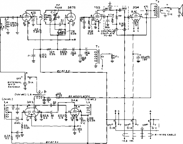 .5 -1.i +1.5 1 + 4.5 Ь -87.5 J Figure 24 SCHEMATIC, HANDIE-TALKIE FOR 2 MH-ERS Coil data rs given in figure 26. Cj-IJ ддМ. butterfly . Johnson 3MBП S,A-B-C-D-C-5 pole, three position rotary switch. Centralab PA-20T5 Tj-700 ohms to grid. Triad A-IX Ti-5 К pri., 6.7 К and 4 ohm sec. Triad M-4Z Fi-Telephone-type carbon microphone. through which the transmitter tuning slugs may be adjusted. These holes are closed with snap-in hole plugs after adjustments are completed. A general view of the transmitter chassis may be seen in figures 25, 27, and 28. Notice that a small shield passes across the r-f stage tube socket, and pin 3 of the socket is grounded to the shield. The shield isolates coil Li from tuning capacitor G which is placed directly below it. The two audio stages and transformer Ti mount at the end of the chassis. The tubes mount parallel to the front panel on a small aluminum angle bracket. Directly below Ti is the 5б7б detector tube, also placed in a horizontal position. The crystal socket, the transmitter coils, the two r-f tubes, and the send-receive switch Si are mounted at the far end of the chassis. A small shield plate is placed between coils and Ls to reduce interstage feedback. Output transformer Ta is located between the 3A4 plate coil (Ls) and the audio tubes. The r-f stage coil Li is wound upon a slug-tuned form made from a concentric trimmer capacitor. The outer electrode of the capacitor is removed, exposing the polystyrene form upon which the coil may be wound. The inner slug of the capacitor serves as the tuning slug of the coil.
Transceiver Wiring techniques are extreme-Wiring ly important when working on VHF equipment that must be compacted into a small space. It is recommended that a pencil-type soldering iron be used, along with small gage wire whose insulation will not melt if it is overheated. All socket grounds and filament wiring are completed first. Coils are wourid and put into position. After the coupling capacitors and other r-f components are mounted in place, the tubes are placed in the sockets and the tuned circuits are adjusted to frequency. It may be necessary to alter the number of mrns on coils Li, b, b, and Lfl due to slight variances in circuit components and tube inter-electrode capacities. 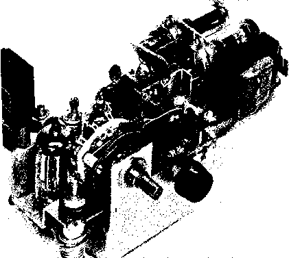 Figure 25 VIEW OF WALKIE-TALKIE CHASSIS SHOWING MAJOR C0MI4>NENTS Oblique view ot chassis looking towards switch Si. Output coil Le is in foreground with 3A5 tube behind It. To right of 3A5 Is 3A4 tripler stage. Coils Ц and Ls are behind 3A4. To right of switch Sj is receiver tuning control Cl. Shield separates Ci front coll L, directly above it. R-f amplifier tube 5687 mounts on vertical plate supporting Ll. Shield be-low r-f tube isolates it from detector components below the chassis. Audio tubes are at right, with Ti. 1 ... 51 52 53 54 55 56 57 ... 80 |
|||||||||||||||||||||||||||||||||||||||||||||||||||||||||||||||||||||||||||||||||||||||||||||||||||||||||||||||||||||||||||||||||||||||||||||||||||||||||||||||||||||||||||||||||||||||||||||||||||||||||||||||||||||||||||||||||||||||||||||||||||||||||||||||||||||||||||||||||||||||||||||||||||||||||||||||||||||||||||||||||||||||
|
© 2026 AutoElektrix.ru
Частичное копирование материалов разрешено при условии активной ссылки |