 |
 |
 |
| Главная Журналы Популярное Audi - почему их так назвали? Как появилась марка Bmw? Откуда появился Lexus? Достижения и устремления Mercedes-Benz Первые модели Chevrolet Электромобиль Nissan Leaf |
Главная » Журналы » Simple coaxial reflectometer 1 ... 52 53 54 55 56 57 58 ... 80 Figure 27 UNDER-CHASSIS VIEW OF WALKIE-TALKIE SHOWING MAJOR COMPONENTS Cbaais of transceiver is specially bent to fit components in smallest possible space. Oscillator coil Li is at left separated from tripler coil Ls by small shield. Output coil Ls is to rear. 5676 detector tube is at right rear, flanked by 20 jxtd. filter capacitor. Audio tubes are under chassis partition at right. Quench filter capacitors are to right of coil Ls. 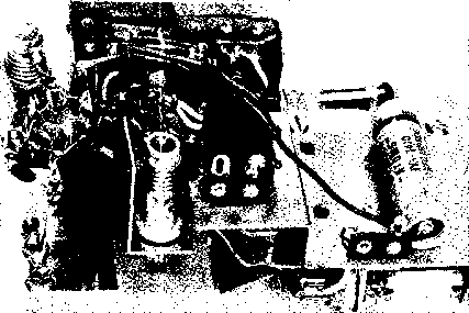 These adjustments may be done quickly and easily with the aid of a grid dip oscillator. After the r-f circuits are adjusted the rest of the transceiver may be wired- Short, direct leads should be used in the r-f circuits and all wires should be routed in the shortest possible paths. Transceiver After all wiring has been check-Alignment ed, the tubes should be removed from their sockets and the filament batteries connected to the unit- The filament voltage at each tube socket should be checked in all three operating positions of switch Sl. JVlake sure the second filament section of the 3Q4 (pin #7) is energized in the transmit position of Si. The bias batteries and B-plus batteries may now be attached to the proper leads. Be sure of the correct battery polarity before inserting the tubes in the sockets. Test the handie-talkie for proper reception first. The slug of coil Ь should be adjust- ed for best reception after the transceiver is assembled and the whip antenna placed in the coaxial receptacle. However, it is possible to place a short piece of wire in the antenna receptacle to pick up a test signal while the transceiver is dissembled on the bench. The coupling between Ь and La should be adjusted for best super-regenerative action and sensitivity . After the receiver is operating, the transmitter should be energized- Tune the slug of coil L4 for reliable crystal operation. A grid dip oscillator held in the proximity of L4 will serve as a r-f indicator. Remove the plate voltage from the grid dip oscillator for this test. Alternatively, oscillator operation may be monitored in a nearby receiver tuned to the 24 Mc. overtone frequency of the crystal. The 3A4 tripler stage may now be tuned for maximum output on 72 Mc. as indicated on the grid dip oscillator. Finally, the grid dip oscillator (or wavemeter) is held in close proximity Figure 28 TRANSCEIVER CHASSIS BOLTED TO PANEL OF WALKIE-TALKIE The chassis is held in place by bolts passed through frame of small speaker. Modulation transformer Tt is visible in foreground with Centralab Couplate at rear of audio tube sockets. Batteries occupy space to left above microphone. Crystal socket is at far right, which is top end ot transceiver. 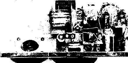 to the 144 Mc. doubler plate coil, Le. This coil is tuned for maximum output at 2 meters. After this preliminary alignment is completed the chassis of the transceiver may be placed in the case, along with the battery power pack. Finol Experience with several of these Alignmeni- units has shown that maximum output is obtained with a whip antenna slightly longer than quarter wavelength. The transmitter stages should be retuned for maximum field strength in a nearby wavemeter and different length whip antennas should be tried. The quarter wavelength whip is nineteen inches long, but whip lengths up to twenty-seven inches should be tried. In general, whip lengths of twenty-four inches or so seem to produce best results with this little transceiver. Input to the final stage of the 3A5 is approximately )2-watt under optimum loading conditions. The operating range between two of these units varies from a thousand feet or so over obstructed terrain to better than three miles over smooth ground. Communication between the handie-talkie and a base station equipped with a sensitive receiver and a high gain beam can be maintained over greater range. 27-6 Six Meter Transceiver for Home or Car The six meter band has become extremely popular within the past few years. The pinnacle of the sunspot cycle, combined with the influx of new amateurs has brought life to an otherwise neglected amateur band. Most of the stations operating on this band employ relatively low power and the amateur having modest power suffers no handicap if he has a good antenna. The growth of mobile operation on the six meter band has been rapid and the need has arisen for a compact transceiver that will work well either in the car or at home. The unit described in this section has been designed to meet this need. This compact transceiver operates in the 50-54 Mc. range. It employs a stable, superheterodyne type receiver and a 10 watt transmitter. The transmitter may be either crystal controlled, or driven with an external variable frequency oscillator. A 5-watt audio system operates from a high impedance crystal microphone and provides 100% modulation of the transmitter. In the receiver mode, the audio system delivers sufficient power to drive an external speaker well above the noise level of the automobile. Small enough to fit comfortably under the dash of todays car, the transceiver delivers a well modulated signal at a total plate power drain of 100 milliamperes at 250 volts potential. Voltage regulation of the plate and filament voltages of the receiver oscillator ensures the maximum stability required for mobile work. Transceiver A block diagram of the trans-Circuit ceiver is shown in figure 30. Eleven tubes are employed, plus a filament voltage regulator. Change-over from receive to transmit is accomplished by a push-to-talk circuit that operates two d-c relays from the microphone control button. The receiver employs a broad-band r-f stage and two i-f stages. The r-f stage uses a 6CB6 television-type pentode with pre-tuned grid and plate circuits. This stage is capacity coupled to a second бСВб mixer operating with grid injection. The variable frequency oscillator is a third бСВб in a Tri-tet configuration. The oscillator circuit (L-Cs-CO tunes the 17.0-I7.7 Mc. range. The plate circuit of this 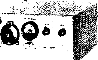 Ф Ш Figure 29 DE-LUXE SIX METER TRANSCEIVER FOR HOME OR CAR Operating ftom a separate power package, this compact transceiver is well suited for the serious six meter operator. A 10 watt crystal controlled transmitter and superheterodyne receiver are combined with a dual purpose audio system in this small cabinet. Receiver controls are at left and transmitter controls at right. Meter serves as S-meter and transmitter tuning indicator. External VFO may be used with transceiver. stage is gang-tuned to the oscillator and covers the third harmonic range of 51-53 Mc. The harmonic voltage is capacitively coupled to the input grid circuit of the mixer stage. Series padding capacitors in the oscillator and tripler stages permit close tracking over the tuning range. An i-f channel of 1 Mc is employed in this transceiver. When the oscillator is considered to be on the high frequency side of the received signal, the tuning range is 50-52 Mc. When the oscillator is considered to be on the low frequency side of the received signal, the tuning range is 52-54 Mc. The broad band r-f circuits of the receiver front end cover the complete range of 50-54 Mc- so that signals on either side of the injection frequency may be detected. This principle is sometimes referred to as super-imposition tuning, wherein the receiver is tuned to two frequencies simultaneously- For example, if the local oscillator is tuned to 51 Mc, simultaneous reception of signals on 50 Mc, and 52 Mc. is possible. Since most amateur activity takes place in the lower one megacycle of the six meter band, the chance of two signals appearing at one point of the dial that in reality are two megacycles apart is remote. Super-imposition tuning greatly simplifies the design of a VHF receiver. Double conversion is not required, and the local oscillator need tune only a relatively narrow frequency range. Saving, in parts and circuit complexity, is obvious. Two stages of one megacycle i-f amplification are used for maximum gain. Five i-f transformers are used to narrow the skirt response of the i-f strip. A 12AL5 serves as the detector, a-v-c rectifier, and automatic noise limiter. Filament voltage to the 12AL5 is reduced to 10.5 volts to provide better noise limiting action. Two tubes are used In the audio system of the transceiver. A 12AX7 dual triode serves as a two stage resistance coupled speech amplifier. Only one section of the 12AX7 is used for reception purposes. The dual triode is capacity coupled to a 12AQ5 audio output stage- A tapped output transformer matches the 12AQ5 to the r-f amplifier plate circuit of the transmitter section, and a low impedance winding on the transformer drives an external speaker for reception. The screen voltage of the 12AQ5 is reduced for receiving operation to conserve power supply drain. The transmitter section of the transceiver uses two pentode tubes. The oscillator is a 6CL6 in a hot cathode circuit employing 25 Mc overtone crystals. Switch Ss in the grid circuit of the oscillator permits selection of an external variable frequency oscillator. The plate circuit of the oscillator (Cs-Ls) is tuned to the 50 Mc. second harmonic of the crystal. A switch (Sl) in the oscillator screen circuit permits the operator to turn on the oscillator stage during reception for zero-beat or frequency marking purposes. The oscillator is inductively coupled to a 5763 r-f amplifier R-F AMP. (.50 MC.) DET.,A-N-L 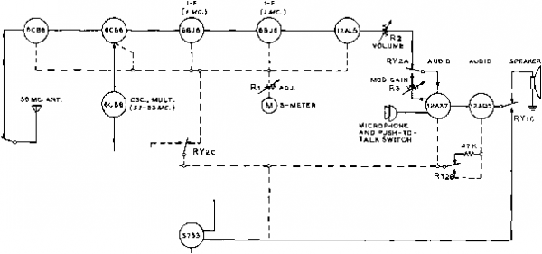 RY1 A REGULATOR OBZ . V-F-O R-F AMP. iSOMC.) RYiB J Bt250V. Figure 30 BLOCK DIAGRAM OF 10 WATT SIX METER TRANSCEIVER ® RYi -0-1 ANTENNA CHANGEOVER S7e3 SCREEN CONTROL SPEAKER CONTROL TO TRANSMITTER OUTPUT CIRCUIT TO J 1 {ANTENNA ) TO RECEIVER INPUT TO *7вЭ SCREEN CIRCUIT TO RYa -SECTION С AUDI 0 CONTROL OPEN  IZAQbSCREEN CONTROL e+CONTROL TO SPEAKER CIRCUIT TO Tl SECONDARY TO GAIN CONTROL . Рз TO GRID, 12AX7 TO VOLUME CONTROL, R 2. TO I2AQ5 SCREEN B+ 2S0 TO 47 К RESISTOR B+TO eCLe, RYl SECTION В 8-1-250 - B-t- TO RECEIVER Ml 4o-i> Ms oi-fcM4 {SEE FieuRE ii ) Figure 31 RELAY AND METER CIRCUITS Relays are shown in unenergized position. Stage, which is plate modulated by the 12AQ5 audio amplifier. The r-f amplifier is bridge neutralized by capacitor Cw for greatest stability at the operating frequency range. The plate circuit of the 5763 is pi-coupled to a 52- or 72-ohm external load. Transfer from reception to transmission is accomplished by means of two d-c relays actuated by a push-to-talk switch in the microphone- The six volt relay coils are connected in series for twelve volt operation. Relay change-ovef operation is shown in figure 31. Relay RY-1 actuates antenna changeover, screen control, and speaker control circuits. Relay RY-2 actuates audio control, 12AQ5 screen control, and B-plus control circuits. Both relays are shown in receive position in figures 31 and 32. Proper tuning of the r-f amplifier is accomplished by a simple crystal diode voltmeter (1N38A) connected in the antenna circuit. The stage is tuned for maximum reading of the voltmeter. A two pole, four position rotary switch (Si) serves to place the 0-1 d-c milliammeter across the appropriate circuits in the transceiver. In position 1 (Ms) the meter serves as a 0-500 volt meter measuring the transceiver plate voltage. Position 2 (Мз) converts the meter into a 0-10 d-c milliammeter measuring power amplifier grid current. Position 3 (M4) monitors the r-f voltmeter output, and position 4 (Ml, M2) places the meter in the a-v-c controlled B-plus line of the receiver where it serves as a signal strength meter. Under normal driving and charging conditions, the voltage of the standard 12 volt battery can vary from 11 volts to 14.5 volts. This fluctuation can raise havoc with the receiver oscillator stability. It is annoying, to say the least, to have the receiver calibration change with variations of car speed and generator voltage. To eliminate this effect, an Amperite ballast tube (R4) is placed in series with the filament circuit of the 6CB6 receiver oscillator tube. This current sensitive device compensates for voltage changes in the filament circuit, holding the voltage at the filament terminals of the oscillator tube within a few percent of a nominal 6.3 volts. The six volt tubes of the receiver are connected in series parallel for operation across the 12-volt power supply. A compensating resistor is required across the filament of the 5763 to equalize the current drain with that of the 6CL6 oscillator. Transceiver Layout Figures 29, 33, and 34 and Assembly provide a general lay- out of the transceiver. The unit is built upon an aluminum chassis measuring 9 x 7 x IVi in size. This assembly fits within a steel wrap-around type cabinet 4i/2 high, and approximately the same length and depth. The cabinet is formed of perforated metal to ensure proper ventilation uhile at the same time reducing spurious radiation to a minimum. Viewed from the top rear (figure 33), the receiver portion of the unit occupies the right half of the chassis and the transmitter and modulator occupy the left half. The external plugs and receptacles are mounted on the rear apron of the chassis as is the modulation gain control, Ra. These components project through a cut-out in the rear of the steel enclosure. All the ceramic variable capacitors that serve as circuit adjustment trimmers are flush (S0-S4MC.) 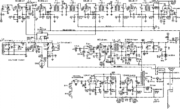
SEE FieuKB 35 DUMMY LOAD BASE VIEW  CND. [-6,12 V.I SOLDER SIX S.3 VOLT, ISO MA. BULBS TOGETHER. JUMPER CENTER TERMINALS TOGETHER. r4 2,3 бСВй OSC. Figure 32 SCHEMATIC, SIX METER TRANSCEIVER Coil data and i-t iranstormer nmditication it given in figure 35. Relay and meter connections are given in figure 31. Cj-Ct-Cs-6-30 /4ifd. Centralab 827C RYi, RYi-3 pole, double throw with 6.3 volt d-c coil. Advance #MG-3C6VA Ci-C,-Sg-C,-3-12 liiifd. Centralab 827B Ti-Ti-7500 kc. if transformer. J. W. Miller Co. 72-W7 C-Ca-75 fiiifd. per section. All-Star Products Co., Defiance, Ohio. Model C3 (see figure 35 for moditieation) C, -7 lifLtd. variable piston-type . Crie 532B T,-5 К pri., 6.7 К sec, and 4 ohm winding. Triad M5-Z - - ..t м,.мтлг1ип<1 HF-35 -Amperlte Ballast Tube #3TF-4A mounted to the chassis and may be tuned from the top of the unit, with the exception of the receiver oscillator trimmer Ct which is mounted below chassis to conserve space. Below the chassis, a small aluminum shield measuring VA long and 1й high is positioned between the oscillator output coil and the receiver r-f amplifier plate coil L2, This is the only interstage shield required in the transceiver. The two transfer relays RY-1 and RY-2 are mounted in the under-chassis area beneath the modulation transformer Tg. Between the relays is placed an 8-terminal phenolic mounting strip. To the side of this strip is placed the midget S-meter potentiometer Ri. All sockets and trimming capacitors are mounted in place using 4-40 hardware with soldering lugs placed beneath the nuts in various convenient locations. Transceiver The wiring of the unit is quite Wiring simple if done in the proper sequence. The underchassis area contains many small components but these need not be crowded, provided proper care is taken in the layout and installation of parts. Be sure the i-f transformers have been modified accord- ing to the data of figure 35 before wiring is started. The majority of components are installed between the socket pins of the various tubes and five large phenolic terminal strips. One of these strips (previously mentioned) is placed between the two transfer relays. A four terminal and a six terminal tie-point strip are mounted in line running parallel to the i-f tube sockets of the receiver, towards the chassis-edge side of the sockets. The i-f stage components mount between these tie-points and the pins of the 6BJ6 and 12AL5 tube sockets. A fourth terminal strip (8 tie-points) is parallel to and directly beside the edge of the chassis adjacent to the r-f tube sockets of the receiver. The smaller components of the r-f section mount between this strip and the pins of the 6CB6 sockets. The r-f coils of the receiver section (Li, L2, La, and L4) are mounted directly to the ceramic trimming capacitors associated with each coil. The interstage coupling coils (Ls and Le) of the transmitter section are mounted to their respective trimming capacitors and may be seen in the center of the chassis in figure 34. 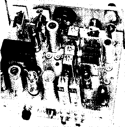 Figure 33 REAR VIEW OF SIX METER TRANSCEIVER CHASSIS Receiver section of unit is ai rigfii witft trimmer capacitors seen on cftas-sis cfecfc. Center section of tftree gang variable capacitor is unused. Transmitter output controls are located at upper left. Filament voltage regulator tube is at rear of chassis, just above modulation level control potentiometer. 5763 amplifier tube is behind modulation transformer, with shielded 6CL6 tube io right. I-f strip runs along center of chassis. Antenna and speaker plugs and power receptacle are along rear lip of chassis. Receiver audio control is at upper right of front panel. After all major components have been mounted to the chassis the various socket ground connections should be made, followed by the filament wiring. The speech amplifier should be wired next, taking care to place small components directly between socket pins to conserve space. All the small components of the i-f system can be mounted above the tube sockets, and in the space between the sockets and the tie-point strips. The power leads from the wired sections of the transceiver should now be run to the two relays. The next step is to complete the receiver wiring. Shielded leads are run to the volume control Rs mounted in the upper-left hand corner of the receiver panel (as viewed from the front). The S-meter wiring circuit should be completed as the final wiring step. Note that the case of potentiometer Ri is hot and should be insulated from the chassis with fibre bushings. Receiver The receiver may be tested be-Check-out fore the transmitter wiring is done. Relays RY-l and RY-2 are in an unenergized position during reception. Examine both relays to make sure that the back contacts (normally closed) are in good operating condition. FIGURE 35 COIL TABLE FOR six METER TRANSCEIVER Ll, Lz, l4-BTUBNS NleE., 3/8 DIAM., 1/2 LONG. l3-7turns №16 E., 1/2 DIAM., 1/2 LONG. Csetv COIL STOCK) Ls, L6- 10 TURNS №226., 5/16 DIAM., 5/16 LONG. ADJUST SPACING BETWEEN COILS FOR MAXIMUM GRID DRIVE, COILS MOUNTEND TC END. l7-6turns № le 1/2 DIAM.. 5/8 LONG. AIRWOUND, Tl,T5-REPLACE lOOJUUFD PADDING CAPACITORS WITH SOOililFD CAPACITORS TO RESONATE Wl NDINGS TO 1 MC. A pov/er supply capable of delivering 250 volts at 100 milliamperes and 12.6 volts at 3 amperes is required to test the transceiver. A 4-ohm loudspeaker is also required- The receiver is energized and the important voltage points are checked with a high resistance voltmeter and should comply closely with the values of figure 32. When the receiver section is determined to be in operational order, a tone modulated 1 megacycle signal should be loosely coupled to the plate circuit of the 6CB6 mixer tube (pin 5) and the slug cores of all i-f transformers tuned for maximum audio signal. As the stages are bought into resonance, the input signal to the mixer tube should be reduced to prevent over-excitation of the stages. Figure 34 UNDER-CHASSIS VIEW OF TRANSCEIVER Changeover relays are located at the left edge of the cfiossis. The i-f amplifier runs down the center of the chassis, with the receiver r-f stages to the right. Transmitter stages are located between front relay and i-f strip. Audio stages are placed along rear of chassis. Small components are mounted between socket pins and adjacent phenolic terminal strips. Note: filament circuit is designed for d.c. operation. If a.c. filament operation is desired, high resistance relay coils operated from the high voltage supply should be employed, 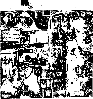 The next step is to check the tuning range of the high frequency oscillator, which should be 17.0-17.7 Mc. The range may be checked with an accurately calibrated receiver or frequency meter. The fixed trimming capacitor determines the overall frequency span of the oscillator, and padding capacitor d determines the range setting. Padding capacitor Q is adjusted so that 17-0 Mc. occurs when the main tuning dial is set to five degrees, allowing a slight amount of overlap at the band edges. As the main tuning capacitor setting is decreased the oscillator will tune to 17.7 Mc. If it is desired to widen or diminish the tuning range, the value of the series capacitor may be changed slightly. Once the proper oscillator range has been established, the tripler circuit should be adjusted to track with it. The main tuning capacitor should be set to 17.7 Mc. and padding capacitor Cs adjusted so that the tuned circuit resonates at 53 Mc, as checked with a grid dip oscillator. The main tuning dial is then reset to place the oscillator on 17-0 Mc; trimming capacitor Ct is adjusted so that the tripler circuit resonates at 51 Mc. Once the two circuits have been brought into rough alignment they may be placed on the nose by adjusting G and Cs for constant grid current in the mixer stage across the tuning range. Temporarily unsolder the grounded terminal of the 0.1-megohm grid resistor of the 6CB6 mixer tube (pin 1) and place a 0-100 micro-ammeter In series with the resistor to ground. Adjust G at the high frequency end of the tuning dial and Cs at the low frequency end until the rectified grid current Is relatively constant across the band. Under proper operating conditions, the reading should be about 15 microamperes. The last step is to align the tuned circuits of the r-f stage. These are relatively broad band and need only be peaked over the usual frequency range of operation. For most purposes they should be resonated at 50.5 Mc. for optimum operation at the low frequency end of the band. Signals above 52 Mc. will be slightly attenuated by this adjustment. If operation at the high frequency end of the six meter band is desired, the circuits should be peaked at 53 Mc. with a consequent slight reduction of performance in the 50 Mc. region. Completion of the Transmitter Section Once the receiver is judged to be In good operating condition, attention should be turned to the transmitter. The lead from the XTAL-VFO switch S= to the v-f-o input receptacle J: on the rear of the chassis should be made of coaxial cable, as should the lead from relay RY-1 to the antenna receptacle Ji. In addition, the lead from the receiver antenna Input circuit to relay RY-1 should be shielded. The majority of small components of both the oscillator and amplifier stages may be mounted by their leads between socket pins and a nearby 5-termInal phenolic tie-point strip. The plate coil L- of the 5763 amplifier stage is mounted above chassis, directly behind amplifier tuning capacitors Cn and Gs. Small National Co. polystyrene feed through bushings are used to support the coil. Neutralizing capacitor Go is soldered to a rotor terminal of plate tuning capacitor Gi. The lead from Go to the cold end of Lc passes through a Ji-inch hole drilled in the chassis. To insure a good ground return, the rotors of Cu and Cn are connected to the chassis with a short, heavy copper strap. The final step is to complete the wiring to the meter switch and the relays as outlined In figure 31. When this is completed, all the transceiver wiring should be completely checked and the chassis thoroughly cleaned of loose bits of solder, wire, etc. Transmitter It is necessary to close both re-Adjustment lays to test the transmitter operation. For the time being, they may be wedged close with a bit of match-stick if a 12-volt d-c supply is not readily available. A 25 Mc. crystal should be plugged in the panel holder and switch S2 set to the XTAL position. Switch Si Is set to OSC position, and the lead from the screen circuit of the 576З amplifier tube to the contact of relay RYl-B is temporarily opened, removing screen voltage from the r-f amplifier. Filament and plate voltage is applied to the transceiver and capacitor Cs Is tuned for oscillation of the crystal. The meter of the transceiver is switched to the GRID (Мз) position and capacitor Сэ adjusted for maximum grid current. A reading of half-scale should be obtained. The coupling between Ls and Lc can be varied slightly to obtain the proper reading. The dummy antenna (figure 32) is next plugged into antenna receptacle Ji and loading capacitor Gs set at full capacity. The plate circuit of the amplifier stage should be resonated at 50 Mc. with rhe aid of a grid dip oscillator coupled to coil Lt. The turns of Lt should be adjusted so resonance occurs at half-capacity setting of tuning capacitor Gi. After this preliminary adjustment has been made, capacitor Gl should be tuned through its range while carefully noting the grid current of the amplifier. Unless neutralizing capacitor Сю has been correctly set by a lucky accident, the grid current reading will show an abrupt kick as capacitor Cii is tuned through resonance. The setting of the neutralizing capacitor should be slowly varied so as to minimize the kick of grid current. After change of setting of Сю, grid tuning capacitor G> should be retuned for maximum grid current. An adjustment of Сю will soon be found that will reduce the grid current variation to an imperceptible kick of the meter. When this point is found, the rotor of Go should be fastened in place with a drop of nail polish and the screen lead to RY-l should be resoldered. Switch Sl is now set to the transmit position and power is again apphed to the transmitter. The meter switch is placed in the OUTPUT (Ml) position, and plate tuning capacitor Gi adjusted for maximum meter reading. At the same time, the bulbs of the dummy antenna should glow. Capacitors Gi and Ga are touched up for maximum indication of the meter. In order to test the modulator section of the transmitter when using an a-c filament supply, it is necessary to disconnect the push-to-talk circuit at pin #2 of the microphone plug; otherwise there will be a loud hum on the audio signal. When this is done, the microphone may be plugged into the jack and the gain control (Ra) advanced. The dummy antenna should increase in brilliance under proper modulation. If the coupling to the dummy load is too tight downward modulation will result, and the bulb brilliance will drop. The capacity of loadi ng ca.p3.citor Ci2 should be increased, dropping the degree of loading. The transmitter is designed to operate into a coaxial transmission line having an impedance value between 50 and 75 ohms. When a high value of standing wave ratio exists on the line the impedance presented to the pi-network amplifier may be of such magnitude as to preclude the possibility of a proper match. It is permissible to add a second mica capacitor in parallel with loading capacitor Gs to extend the operating range of the pi-network. If more than 50 fifiid- has to be added, the SWR ratio should either be lowered by proper adjustments to the antenna, or the length of the transmission line between the transciver and antenna should be altered in order to present a more reasonable load to the amplifier circuit. Maximum carrier power output when properly tuned is about 41/2 watts. All r-f adjustments should be carried out with the purpose of obtaining maximum reading on the output meter of the transmitter under a given set of antenna conditions. Under these conditions, maximum transceiver plate current is 100 milliamperes at a plate potential of 250 volts. The Meter A final word should be said Circuit about the metering circuit of the transceiver. The particular meter used has a d-c resistance of 100 ohms, and a full scale reading of one miiliampere- In order to simplify the problem of obtaining meter shunts, the meter is converted into a 0-1 voltmeter by adding a 900 ohm resistor in series with the meter in the grid current position (Мз)- The meter is placed across a 1000 ohm shunt in this position. Since the resistance of the meter circuit and the shunt are equal, one-half the grid current flows through the meter, and one-half through the shunt. Thus, when the meter reads full scale (one miiliampere), two milliamperes of grid current are flowing in the grid return circuit. When the meter is switched to S-METER position (Ml, Мг) of switch Sa, the meter is placed in a bridge circuit, the variable leg of which is the internal resistance of the a-v-c controlled, i-f amplifier tube. The bridge is balanced by proper setting of Ri; meter sensitivity is set by the value of the series resistor (2.2K). Dropping the value of this resistance will increase the sensitivity of the meter. When Sl is set to the VOLTS position, the meter is placed in series with a 500 К resistor (Ms) and is converted into a 0-500 volt meter to check the operating potential of the plate supply. 27-7 A Hot Transceiver for 28 Megacycles This little transceiver is vivid proof that DX can be easily worked on the 10 meter band. During a test period of two weeks, using a dipole antenna, over 80 foreign phone contacts were made in four continents, including three contacts with India. Power input to the transmitter section of the unit was under 10 watts. Admittedly, such DX is not a daily feature with such low power, but it does prove that a few watts into a well situated antenna can work wonders on the 28 megacycle band- The 28-10 transceiver (28 megacycles, 10 watts) is designed to operate over the range 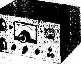 of 28.0-29.7 Mc. The receiver portion employs five tubes in a single conversion circuit. Two tubes do double duty as the audio section for reception and the modulator for transmission. Four tubes are used in the r-f section, maicing a total of eleven tubes plus a voltage regulator. A voltage doublet selenium rectifier supplies plate voltage for the complete transceiver. The whole unit weighs less than eleven pounds so it is readily transportable, even by air. The power source is 115 volts, 50-60 cycles, a-c. Figure 36 TEN METER TRANSCEIVER HAS SIMPLE CONTROL PANEL Used with a dipole antenna, this 10 watt 28 Mc. transceiver has made three contacts with India. Main tuning dial ol receiver is at center with send-receive switch below it. At upper right is combination S-meter and transmitter tuning indicator. Transmitter tuning controls are at left with push-to-lero switch near receiver tuning dial. Unit features self-contained power supply for lis volt operation. Transceiver A block diagram of the trans-Circuit ceiver is shown in figure 37. Change-over from receive to transmit is accomplished by a ceramic rotary switch. Si. The receiver employs one r-f stage and two i-f stages for optimum selectivity and sensitivity. The r-f stage employs a low drain 6BJ6 remote cut-off pentode with tuned grid and tuned plate circuits. The plate of the r-f tube is shunt fed through a 10 К composition resistor and the tuned circuit is placed in the low potential grid circuit of the next stage. A 6U8 is employed here as a combined mixer and oscillator. Grid circuit injection is used. The triode section of the 6U8 serves as the local oscillator, tuning from 26.5-28.2 Mc. for 10 meter coverage. A three section variable capacitor ClA-B-C simultaneously tunes the R.F. AMP. MIXER. 03C. 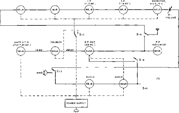 REGULATOR ( 0A2J - PHONE Figure 37 BLOCK DIAGRAM OF TEN METER TRANSCEIVER 1 ... 52 53 54 55 56 57 58 ... 80 |
|
© 2026 AutoElektrix.ru
Частичное копирование материалов разрешено при условии активной ссылки |