 |
 |
 |
| Главная Журналы Популярное Audi - почему их так назвали? Как появилась марка Bmw? Откуда появился Lexus? Достижения и устремления Mercedes-Benz Первые модели Chevrolet Электромобиль Nissan Leaf |
Главная » Журналы » Simple coaxial reflectometer 1 ... 55 56 57 58 59 60 61 ... 80 6BJ6 SE£ Fie. Л NOTES! 1 - SEE Fie. ia FOR FIL. WIRING 2- C.=.OJ DISC CEKAMIC iALL RESISrORS WATT UNLESS OTHERWISE NOTED 4-Si IN XTAL Ш' POSITION S-RYl IN RECEIVE POSITION 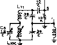 -1W- 47 H 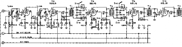 pt- H-V Fgvp A-V-C BUS R4.l5n. iRYiB RYicL s7 METER ZERO SEE FIO. 17- Figure 15 SCHEMATIC, l-F PORTION OF RECEIVER SECTION Cj, Cj-30 niifi. сегатк trimmer. Centralab 827-C Cj-12 fLufd. ceramic trimmer. Centralab NPO Lio-Ln--4ee figure 21 for coil information A(, O.I d.c. mifliammeter. De-/ur #JJ2 RYiB, RYjC-,See figure 19 SjA-SiF-2 wafers, 6 pole, 2 position each wafer. (Two Centrafab PA-9 wafers with РЛ-301 index assembly; Г]-Гз-Modified 1500 kc. sJug-tuned interstage I.f transformer. (J.W. Miller 12-W1). Remove internal resonating capacitors. Replace plate capacitor with SO iiifd. mica, and grid capacitor with two loo li/ifd. mica capacitors connected in series. Ground common tap of capaciiors. Transformer now tunes to 2009 kc. Tj-1500 kc. sJug-tuned i-f output transformer. (J. W. Miller 12-У/2). Modify as above. X3-X1.-Lattice crystal set. 2007 kc. and 2011 kc. Precision Crystaf Labs., Santa Monica, Calif. Xi-Xs-Same as Xj-Хл. RFC-39 Jib. J. W. Miller 4628 > О О < о n Ф Ч о < ception by depressing the zero switch Se, which applies plate voltage to the oscillator by way of the receiver circuits. The balanced output circuit of the oscillator stage is inductively coupled to a push-pull miniature beam amplifier stage employing a 6360 (Vic). The grid circuit of this stage is broadly resonant to the 50 Mc. region by virtue of the interelectrode capacitances of the tube. For six meter operation, the 6360 functions as a class-C amplifier with the plate circuit (Lis-C?) tuned to 50 Mc. Bias and screen voltages are set for optimum operating values by segments of switch Sa. In addition, the plate return of the stage is routed through the secondary of modulation transformer Ts. The r-f output circuit is inductively coupled to the 50 Mc. antenna coaxial receptacle through relay contacts RY2A. , When switch Ss is moved to the 144 Mc position, the aforemenrioned бЗбО stage is converted into a high efficiency rripler stage, providing output in the 140- 150 Mc. region. Switch segment SaD raises the operating bias on the stage, segment SaE drops the screen voltage, and segments SaA-B select the proper plate rank coil, Ln. A separate amplifier stage employing another 6360 dual beam power tube (Vn) is used for 2-meter operation. The tube functions as a class-C amplifier and is driven by rhe push-pull tripler stage (Vie). The grid circuit of the 144 Mc. amplifier is inductively coupled to the tripler, and the plate circuit (G-L15) is inductively coupled to rhe ourput circuit. A separate antenna гесергаЫе (Ji) is used for 144 Mc. operation. Flare voltage is applied to this tube by switch section SsF- The use of inductive coupling between the three stages of the transmitter reduces spurious emissions to a minimum. Channel 2 television interference, so common to six meter transmitters is absent when this transmitter is used, thanks to the combination of interstage inductive coupling and the employment of 25 Mc. crystals. Power input to the modulated stage on both bands is close to 18 watts, permitting 1 carrier power of over 10 watts. , Transmitter adjustment is greatly simplified by the use of r-f volt-meters connecred to the output circuits of each amplifier stage. Small germanium diodes (Di and D2) are used to rectify a minute portion of the output voltage which is read on rhe mulri-meter Mi of the transmitter. All tuning adjustments of the transmitter are conducted so as to enhance the reading of the r-f voltmeter under a given set of antenna conditions- The transmitter is plate modulated by two 6AQ5 tubes (Vis, V20) operating class ABi. Plate voltage may be removed from these tubes and from the modulated amplifier by the tune-operate switch Ss. A single 12AX7 serves as a two stage resistance coupled audio amplifier, having sufficient gain for the use of a crystal or dynamic microphone- 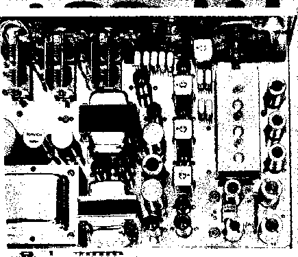 Figure 16 REAR VIEW OF VHF TRANSCEIVER At the left rear of the chassis is ihe dual purpose power supply with the vibrator and filter capacitors mounted in front of ihe power transformer. At ihe front of the chassis are the two 6360 tubes and the tuning capacitors of the transmitter. Note that the stages are isolated by shields placed between ihe tuning capacitors and tubes. The modulaior and power supply filter choke occupy ihe center por- / Hon of ihe chassis, with ihe receiver i-t section to ihe right. In front of the i-f strip are the transmitter crystals and the lattice crystals. At the right of the chassis are located ihe TV-type variable inductor tuner and ihe three tunable i-f stage tubes. At ihe rear of the chassis, directly behind ihe tuner are the two VHF conversion oscillators. The microphone receptacle and audio gain control are on ihe rear lip ot the chassis, directly below the cascode stages. Cabinet and chassis custom made by California Chassis Co., Lynwood, Calif. 6AL5 Viz 12AX7 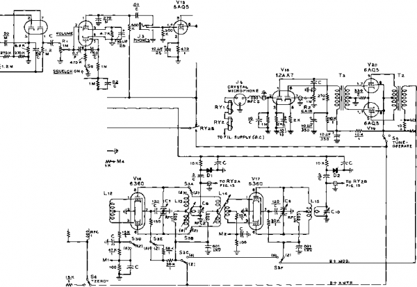 avc BUS b+regulated b+hv receiver tx output indicator a- BUS fil, Ml M2 . Ms- meter circuit saa-b NOTES 1 - S££ FIS. 16 РОЙ FILAMENT WIRING j4 г-С-.001JUF DISC CERAMIC SPEAKER 3- ALL RESISTORS 0.5 W. UNLESS OTHERWISE NOTED. IN тл MC. POSITION 4®--fl 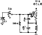 rfc 15K 3 - Ml=0-10 MA. M2-= 0-10 Ma. Мз, M4. = 0- tOOMA.
Figure 17 SCHEMATIC, TRANSMITTER AND AUDIO SECTION OF TRANSCEIVER Cs, Cj, Cs-75/75 mmW. HammatXand HFD-15X Cs, Cc-30 liiifd. Johnson 25J72 Di, Di-Germanium diode 7 N8 7 Lii-Lis-See figure 2 7 for coil information RFC-,-7.0 iih. Olimite Z-SO RFCl-1.8 fill. Ohmite Z-I44 RFC}-0.15 tih. J. W. Miner 4644 SjA-SjF-Some as 5 figure 75. Space decks so coils Li. and 1ц fit between the decks. S,-SPOr push-button switch Si-2 poie, 3 position non-shorting switch. Mallory 3223-G RY ry2-See figure 19 Мг-0-7 d.c. milliammeter. De-jur #112 Tl-25 watt modulation transformer, 10K pri., 5 К see. Stancor A-3845 Tj-Interstage transformer, 7:3. Stancor A-53C X7~-2426 Me. overtone crvstal. Precisian Crvst J Co.. Santa Manira. Calit. The Power Supply Section. The complete transceiver requires a plate supply of 250 volts at 150 milliamperes, and either 6.3 volts at 7.8 amperes or 12.6 volts at 3-9 amperes. These voltages may be obtained from the power supply whose schematic is given in figure 18. The high voltage portion of the supply employs a voltage doubler selenium-type rectifier system operating from a 117 volt half-wave winding of the power transformer. This transformer has two auxiliary windings. One winding may be used for 115 volt, 50-60 cycle operation, and the other one is intended for vibrator opera-ation from either a 6- or 12-volt dc. primary source. The choice of a.c. or d.c. operation may be made by inserting the correct terminal plug in receptacle SOi, mounted on the rear of the transceiver chassis. RFC 3 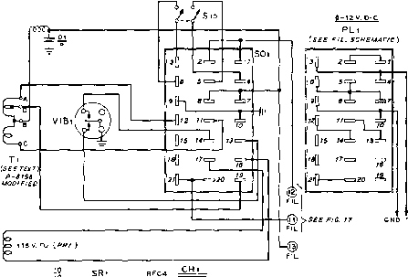 115V. A-C PL2 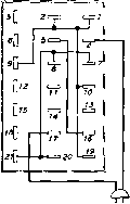 0117V. b-l-HV 6-l2V0LrFILAMENT SCHEMATIC 20 21 ! 2 7 8 Xc W сф: V2< 115V. -fV 1 i i V. < I 15 VOLT Wl RING ,-с>.ЛГ!П5>-*e.3v. !9 >0J > ~ C> I17V. О e-l2 VOLT D-C WIRING 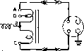 VIBl Figure 18 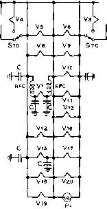 >V1 с =,007 CERAMIC CAPACITOR FOR 8-VOLT OPERATION JUMPER PINS г-a IN PL 1 Ъ-JUMPER PINS 7-20 /Л/ PL I . FOR 12-VOLT OPERATION 6.-JUMPER PINS 10-20 PL 1 . SCHEMATiC, POWER SUPPLY OF TRANSCEIVER CH,-4 h. ai US ma. Siancor C-1410 RFCj-4 ith., 6 amp. J. W. Miller 5221 RfC,.-2.S mh., 200 ma. J. W. Miller 5222 S, -DP5T toggle switch, 12 amp. H & H 80600-268 50i-21 terminal receptacle. Cinch-Jones P321-SB 5Ri, SR!-Selenium rectifier, 156 volt, 250 ma. International Rectifier Corp. 6R5250 PL PJ.,-2? terminal plug. Cinch-Jones S321-CCT T,-117 volts at 200 ma., three 6.3 volt windings. Stancor P-81S8 (modify as per text). VIBl-Radiart vibrator type 5503-6 (6 volt) or 5503-12 (12 volt) P,-6.3 volt, ISO ma. Pilot lamp (brown bead) St-4 pole, 2 position. Centralab PA9 deck with PA-300 hardware. The power transformer is made from a TV-replacement type, with a new vibrator winding replacing the usual 6.3 volt filament windings. Information covering the conversion of the transformer will be found later in this section. The special winding may be arranged for either 6-volt d.c. or 12- volt d.c. operation, but not both. Thus, the choice of d.c. supply voh-age must be determined before the transformer is modified. The filaments of the transceiver are arranged in a series parallel circuit so that they may be operated from either 6- or 12-volts d.c, or 6-3 volts a.c. with no change in circuitry. The appropriate filament connections to the power supply are automatically made when the proper terminal plug is inserted in SOi. A simplified drawing of the primary power wiring of the transceiver is shown in figure 18. Relay and Switching Circuits- The control circuits of the de-luxe transceiver are shown in figure 19- Two relays control change-over operation. The relay coils are of the d-c type, and are connected in series with the push-to-talk button of the microphone and the filament voltage supply. Closing the microphone switch grounds one end of the relay coil circuit and actuates both relays. Relay RYi controls the 144 Mc. antenna changeover, and switches the S-meter to the r-f output meter circuit of the transmitter section. Relay RYz conrols the 50 Mc. antenna changeover, and switches the B-plus from the receiver to the transmitter. Meter Ma serves as a multi-meter for the transmitter portion (figure 17). The basic meter has a 0-10 d.c. millammeter movement and is used as-is for measuring the grid current of Vie and ViT, Meter switching is accomplished by means of Ss. The third position of the switch connects the meter across the shunt in the plate circuit of the modulated amplifier stage. The resistance of the shunt is chosen so that full scale meter deflection is 100 milliamperes. Transceiver Layout and Assembly The transceiver is housed in a special cabinet measuring 14 long, 10 deep, and ЬУг high. The cabinet is formed from cane metal stock and has a removable front panel. The back, which is also made of solid material is welded to the wrap-around cane-metal cover. The chassis of the unit is made of sheet steel which is copper plated after all major holes have been drilled. Chassis height is 2 inches. Placement of the major components may be seen in figure 16. The receiver section occupies the right-hand por- RELAY SWITCHING CIRCUIT (SHOtTN UN£N£ReiZEO) R Yi Г-2>, R-F COIL A т-о- TO J1 XMTR ANT COIL TO V9 В ~-o- TO + S-METER j-o-* TO Vio С ~-o- TO-S-METER t-TO R-F DIODES I-o- - e\ R-F COIL A T-0-* TO J 2 t-a-m. XMTR ANT COIL о- TO RECEIVER В Г-о* то e+ JUSED TO CONTROL CIRCUIT IN MICROPHONE TO FILAMENT VOLTAGE SUPPLY TRANSCEIVER CONTROLS SWITCHES Sl-SELECTIVITY S2-XMTR CRYSTAL SS-BANDSWITCH. XMTR S4-FI LAMENT SS-TUNE-OPERATE Se- ZEROTUNE S7-BANDSWITCH, RECEIVER Sa- METER SELECTOR, XMTR s9-SQUELCH SlO-POWER (BACK OF CHASSIS) POTENTIOMETERS R 1 - RECEIVER VOLUME R2-XMTR AUDIO GAIN r3-S-METER ADJ. Figure 19 RELAY CONTROL WIRING AND LIST OF TRANSCEIVER CONTROLS RYi, RYj-3 pole, DT. Advance MF3C/6VD. Hook coils in parallel for 6 volt operation. tion of the chassis, with the power supply to the rear left, and the transmitter at the upper left of the photograph. The variable TV-type tuner is panel driven by the main tuning dial through a simple speed reduction gear (Crowe). To the side of the tuner are tubes V=, Ve, and V7. To the rear of the tuner are the two separate front end sections of the receiver- The two cascode stages are in the corner, with the 6J6 mixer/oscillator tubes to the left. The various coil slugs and tuning capacitors are mounted to the chassis deck and are adjustable from the top of the unit. Near the center of the chassis and running from the front to the back is the 2009 kc. i-f strip. The four crystals of the i-f filter are seen near the front of the chassis directly behind i-f transformer Ti. To the left of the i-f strip arranged in a line are the voltage regulator tube Vi4, the first lO/tfd. filter capacitor for the speech amplifier, the speech amplifier tube Vis, the second lO/xfd- filter capacitor, and the receiver audio amplifier/ squelch tube Vn. To the left of these components are the two 6AQ5 modulator tubes and transformers Ta and Тз. In the far left corner of the chassis are placed the power transformer Tl, the vibrator VIBi, and the two power supply filter capacitors. Note that the case of one of the capacitors is hot to ground and the unit is mounted on a fibre base ring. The transmitter components occupy the upper left chassis area of the transceiver. The 6CL6 oscillator stage is at the center of the chassis with tuning capacitor Cr, to the left. A small aluminum shield isolates the oscillator components from the бЗбО buffer/amplifier tube. A second shield plate is placed between the second stage tuning capacitor Cj and the 63 60 144 Mc. amphfier. Space is provided on the chassis to mount five miniature crystal holders for the transmitter oscillator circuit. A small aluminum clamp holds five additional crystal sockets to the rear of crystal selector switch S2, as seen in the under-chassis photograph of figure 20. The power supply area beneath the chassis is separated from the remainder of the circuitry by a 2 inch high copper shield that encloses the selenium rectifiers and other small supply components. Leads passing out of this compartment go through chassis mounting type miniature feedthrough capacitors mounted in holes in the shield {Centrdab PT-IOOO). The broad-sharp switch Si may be seen in the upper left area of the chassis. Each segment of the switch is placed over a group of i-f crystal sockets so that the leads from the crystals to the switch contacts are extremely short. To the left of this switch is the S-meter zero potentiometer Ri. The receiver bandswitch Si is located adjacent to the cascode amplifier stages at the rear of the chassis and is actuated from the panel by an extension shaft. The r-f section of the transmitter is visible in the upper right area of the chassis, running parallel to the front panel. A small brass shield is passed across the center of each of the 63 60 tube sockets. The shield passes between pins 1 and 9, and 3 and 4. Transmitter band-change switch Sa is located in the center compartment and the adjoining shields prevent coupling between the coils of this circuit and either the 144 Mc. amplifier coil or the 50 Mc. oscillator coil. Transceiver The transceiver is a complex Wiring piece of equipment and should be wired with care. Space is at a premium and wiring errors are difficult to find when working in a small area. It is therefore suggested that the unit be wired in sections. The receiver should be wired first, and placed in operation with an auxiliary power supply. The transmitter may be wired next and tested for operation with the receiver. Finally, the power transformer should be converted and the power supply can be wired and tested within the transceiver. The final check is to make sure that all sections operate properly as a complete system. Wiring the Receiver Section. The receiver section should be wired first. It is imperative that all r-f wiring and ground leads be short and direct. As many components as possible are mounted between the pins of the tube sockets and the socket ground lugs. Miniature disc ceramic capacitors are used for bypass pur-  Figure 20 UNDER-CHASSIS VIEW OF TRANSCEIVER General layout ot the components below the chassis may be seen in this view. At the lower right are the power supply components, separated from the rest ot the circuitry by a copper shield. RYi, ВУг, and the audio driver transformer are just above this shield. Across the front of the chassis is the transmitter section with the inter-stage shields mounted across the tube socfrets. At the center is the crystal switch with five crystals mounted to the water of the switch. Directly behind this switch is the i-f section of the receiver and the audio output transformer. In ihe lower left corner are the cascode r-t stages and ihe bandswitch for the receiver which is mounted on a small bracket ami panel driven with an extension shaft. In front of this switch are the components of the tuned first conversion stage. The trimmers used with the TV inductuner are mounted on ihe tuner terminals. Sections of Ya-inch coaxial cables conned ihe various antenna circuits io the change-over relays and ihe coaxial antenna receptacles on the rear of ihe chassis. FIGURE 21 COIL TABLE FOR 2 AND 6 METER TRANSCEIVER receiver section, figures 14 and IS Ll - st. го е., Э/в dia., 1/2 long. tap 2 1/a t. From ground end. Lz- 1 г t * 20 e, 3/18 dia, 7/16 long. mount between PI n3 and pine of socket Vi. l3, l4-5 t. # 18 e. 1/4 dia., spaced wire dia. on CTC iron core form PLSe. center-to-center distance between l3 and l4 is 3/4 . Lb- PLATE WINOINS - 8t. 16 e, 5/16 oia. 1/2 long. QPID WINDING 1 t- plastic hookup wire between two cold end turns of plate winding. Le-10 t. 20 e. 3/6 dia., 1/2 long. tap 4t from gnd. end l7, La-iet.m 20 e. closewound on CTQ iron core form PL56. center-to-center distance between l7 And Le is 3/4 . L>- PLATE WINDING : 9t. 16 e, 5/16 dia. 5/8 long. GRID WINDINe 1 t. plastic hookup wire between two cold end turns of plate winding. L10A,b, с -MALLORY INDUCTUNER, vhf tv type, MODEL 303 Ll1- 0.33 jjh. J.W. MILLER 4S 6 r-f choke. TRANSMITTER SECTION. FIGURE 17 Ll2- PLATE WINDING 12T. 16, 3/4 DIA. 3/4 L. BtW ЗОН GRID WINDING- 7T. 16. 1 DIA. 9/16 L. BtWiOlS PLACE PLATE COIL WITHIN CRID COIL. CIRCUIT RESONATES TO 24-26 MC. REGION. PLATE WINDING: 1вТ. 1бЕ. 1/2 DIA.. 1 1/2 L.WITH 1/4 SPACE AT CENTER OF WINDING. CIRCUIT RESONATES TO 50-54 MC. REGION . antenna WINDING 3 T. *gO E. 1/2 DIA. 1/4LONG AT CENTER OF PLATE WINDING. \-1A-PLATF WINDING! в T. 16 E. 1/2 DIA., 1 1/2 L. WITH 1/4 SPACE AT CENTER OF WINDING. CIRCUIT RESONATES TO 144- 14 MC. REGI On . GRID WINDING 4 T. * 20 E. 1/2 DIA. 1/4 LONG AT CENTER OF PLATE WINDING. \-1i-PLATE WINDING: SAME AS L14, 14 E, WIRE. ANTENNA winding: 3T. 20E., 1/2 DIA. 1/4 LONG AT CENTER OF PLATE WINDING. poses in the r-f section of the receiver and every attempt should be made to keep the leads as shorr as possible. Components associated with tubes vs, vo, and v? are mounted between the socket pins and an eight terminal phenolic tie-point strip artached to the side wall of the chassis immediately above the sockets. Trimming capacitors сз, c4, and cs are mounted directly to the terminals of the tv tuner. A twelve terminal phenolic strip mounts to the right of the i-f section of the receiver and supports various components of these stages. After the majority of components have been wired, the r-f coils of the receiver are wound and soldered in position. They should be adjusred to resonance with the aid of a grid-dip oscillator. The first tunable i-f circuit (LioA-сз) and the 6BE6 grid circuit (L10B-C1) may be adjusted with the aid of the grid-dip oscillator to cover 30 - 34 Mc. as the main tuning dial of the receiver is tuned throughout its range. The mixer circuit (boc-cs) covers the range of 28- 32 Mc.  -iW- о SRi CHi 1 x , 250 J± i tl-souF -OB+ e.3v. Tl - STANCOR p-eise (UNMODIFIED ) 6.3V. Figure 22 TEST POWER SUPPLY FOR TRANSCEIVER Testing the Receiver Section. After the receiver wiring is completed, it should be thoroughly checked for errors and omissions. Have another person check your wiring, as it is often difficult to find your own errors. When you are sure of the circuitry the receiver section may be connected to the test power supply shown in figure 22. This supply makes use of the transceiver components and may be wired breadboard style for the duration of the tests- A speaker is connected to the output jack of the receiver, and a modulated test signal of the intermediate frequency is injected on pin 5 of the бВЕб mixer tube (vn)- A very small capacitor is used to couple the if signal into the receiver. Remove the 6j6 oscillator tube (Vt) for this test. The signal generator can be of the BC-221 type capable of being accurately set to a frequency half-way between the crystal frequencies of the lattice filter. (In this case, the mid-frequency is 2009 kc.) Switch Si is set to the sharp position and the tuning slugs of the i-f transformers are adjusted for maximum audio output. As the i-f strip is brought into alignment, the coupling to the signal generator should be reduced to prevent overloading. The 6j6 mixer tube is now replaced and the signal generator is tuned to the first intermediate frequency of 34 Mc. The tuner is adjusted to the high frequency dial setting and oscillator trimming capacitor G adjusted until generator is heard. R-f padding capacitors сз and C-t are adjusted for maximum signal strength. If a short antenna is attached to the rotor arm of transfer switch SiA, signals in the 30 - 34 Mc. range should be easily received. Switch Si is next set to 50 Mc. and the r-f amphfier (va) and mixer tube (vs) for this range are placed in their sockets. Oscillator tuning capacitor d and the coupling between coil Lj and the crystal feedback winding are adjusted for stable operation of the oscillator stage. The oscillator may be monitored in a nearby receiver tuned to 84 Mc. A signal in the 50 - 54 Mc. range is now injected in the antenna receptacle (j2) of the receiver section, and the adjustable slugs of coils L? and Le tuned for greatest signal response- The last step is to adjust the slug of antenna coil Lj. Switch S7 should be set to the 144-148 Mc. range and tubes Vi and V2 are placed in their sockets. Oscillator operation is checked at 114 Mc, and coils L, Lj, and Li are adjusted for maximum signal response in the 2 meter band. When the receiver is operating properly on both bands, the transmitter section of the transceiver may be wired and tested. Wiring the Transmitter Section. The r-f section of the transmitter is wired first. Coupling coil l12 between the oscillator and buffer is made of two sections of coil stock that are telescoping, and the plate coil is placed within the grid coil. Coils Lis and L и are mounted between the wafer secrions of Switch Sa. The 50 Mc. antenna coil is placed between the two windings of Lia, and the 144 Mc grid coil of the 2 meter amplifier is placed between the dual windings of coil Lh. The various resistors associated with the bandswitch are mounted between the terminals of the switch. The 2 meter plate coil l15 is fastened to the terminals of tuning capacitor Co, which project through V-inch clearance holes cut in the chassis. The 2 meter antenna coil is supported on two miniature ceramic insulator posts mounted adjacent to Lis. When the r-f wiring is completed, the various coils may be adjusted to operating frequency range by varying the spacing between the turns. The audio section of the transmitter should be wired next. This is a straightforward operation and comparatively simple. Small shielded leads are run from the second section of the 12AX7 speech amplifier to the audio gain control Ri mounted on the rear apron of the chassis near the microphone jack. A shielded lead runs from the microphone jack to the first section of the 12AX7. The coils of relays RYl and RYl are connected in series with the control pin of Js, and are returned to the filament circuit of the transmitter. Testing the Transmitter Section. The transmitter is now temporarily connected to the auxiliary power supply and the 6CL6 oscillator tube and an appropriate crystal are inserted in their respective sockets. A test lamp should be made from a 6.3 volt, 150 ma. (brown bead) pilot lamp attached to a small loop of wire. This test lamp is coupled loosely to os- cillator coil L12 and will light brightly when the oscillator stage is functioning. Capacitor Co is adjusted for steady operation of the oscillator. Bandswitch Ss is now set to 50 Mc. and switch Ss is set to the tune position removing plate and screen voltage from the amplifier tube. The 6360 is inserted in the buffer socket and meter switch Ss is set to read the grid current of this stage- A reading of about 3.5 milliamperes can be obtained by proper adjustment of capacitor Cs. The plate circuit of the 50 Mc. stage should be set to approximate resonant frequency with a grid-dip osilclator and a dummy load or antenna is attached to the 50 Mc. antenna receptacle Jj. Switch Ss is now set to the operate position and the push-to-talk relay circuit actuated. Amplifier tuning capacitor C7 is adjusted for maximum meter reading when the meter is switched to the r-f voltmeter position. Plate current of the бЗОб tube under this condition is approximately 70 milliamperes- The aaual value of plate current may be checked by setting meter switch Ss to the amplifier position (0- 100 milliamperes). The next step is to check the modulator. Insert tubes v18, Vi9, and V~o in rheir respective sockets. Advance gain control Rs while speaking into the microphone in a normal tone. When checked in a nearby receiver the modulation should be clear and crisp. After the transmitter section is operating properly on 50 Mc, attention should be given to the 2 meter section. A 144 Mc. antenna is attached to receptacle Ji, and the бЗбО amplifier tube (V17) is inserted in its socket. Switch Ss is placed in the tune position, and the coupling between the grid coil of this stage and buffer plate coil Lh adjusted for 3.5 miUiam-peres of grid current to Vu. Switch S.i automatically activates tube Vn when the switch is placed in the 144 Mc. position. Finally, switch Ss is placed in the operate position and the tuning (C ) and loading (Сю) controls are adjusted for maximum indication on the r-f voltmeter. Plate current to the 2 meter stage is held at 70 milliamperes as measured on the amplifier position of meter switch Ss- The bandchange operation will now merely consist of selecting the proper transmitting crystal, setting Sa to the proper position, and adjusting the transmitter controls for maximum reading of the r-f voltmeter. The complete bandchanging operation takes about fifteen seconds. The Power When the transceiver is in work-Supply ing order, attention should be rurned to the power supply sec- tion (figure 18). At the time of construction, no power transformer was available that would provide the desired voltages and at the same time be capable of operation from both a 115 volt a.c. and a d.c. vibrator primary source. It is necessary, therefore, to find a power transformer that has suitable high voltage windings and to remove the filament windings, replacing them with a special multi-purpose winding that will fill the bill. The Stancor P-8138 was used in this transceiver, and does the job nicely. This transformer has a 115 volt primary winding, a 117 volt secondary winding designed for voltage doubler service, and three 6.3 volt filament windings. The three filament windings are on the outside of the transformer and may be easily removed. Power Transformer Modification. The four transformer bolts should be removed, exposing the copper shorting band of the transformer, which is taken off. Take off the layers of cambric tape to expose the uppermost filament winding. Now, remove the unused filament windings, being careful not to damage the other windings of the transformer. A new winding made of enameled wire should now be placed over the remaining windings. This winding will be for either six or twelve volt operation, and will have a voltage tap for filament operation when the supply is run from alternating current. During battery operation the filaments of the transceiver will be run directly from the d.c. primary source. Decide whether you want a six or twelve volt primary winding. The six volt winding will be made of #14 wire, whereas the twelve volt winding will be made of #16 wire. Each winding will have a tap at the proper point to provide voltage for the tube filaments. This new winding is shown on transformer Ti, figure 18. The new winding will be put on in two halves, since two separate windings are required for proper operation of the full-wave vibrator. The six volt winding consists of two separate windings of 14 turns of #14 wire. The windings are wound on in series, with the two adjacent leads brought out as a center tap (see terminal B, Ti, figure 18). The 6.3 volt filament tap (terminal D, Ti) is placed ten turns from the junction of the two windings (point B). The windings should be carefully taped in place and the transformer reassembled. If twelve volt operation is desired, two separate windings of 28 turns of #16 wire are wound in series on the transformer. The filament tap for a-c operation of the filaments (D) is placed at the 12.6 volt spot on the winding, or twenty turns from point B. Thus, the filaments work as a six volt string for 6/115 volt operation and as a twelve volt string for 12/115 volt operation. The two different arrangements of plug PL-2 necessary to accomplish this are shown in figure 18. Testing the Power Supply. After transformer Tl has been modified, the power supply should be wired in accord with figure 18. Before it is used with the transceiver, it should be tested with both a.c. and d-c input circuits. The high voltage system should develop approximately 250 volts across a 1600 ohm 50 watt resistor, and a full 6.3 volts should be measured across a 1 ohm, 10 watt filament load resistor. The 12 volt configuration should develop the same high voltage under a similar load, and should deliver 12.6 volts across a 2 ohm, 10 watt resistor. If it is found that the voltages developed during operation from the d-c source are lower than the corresponding voltages derived from a-c operation, it is an indication that the modified primary winding has too many turns. The transformer should be removed from the installation and one turn removed from each half of the primary winding. This will boost the d.c. plate voltage about 10%. After the voltage has been set, the power supply wiring and switching circuits of the transceiver may be completed. 28-4 A Miniaturized SSB Tronsmitter for 14 Mc. This 40 watt p.e-p. sideband transmitter was designed to provide the greatest amount of talk power for a given size and weight. It was built by W6AVA expressly for the purpose of permitting amateurs in far-off countries to have the opportunity to experiment with SSB transmission. The completely self-contained transmitter has been shipped around the world by air freight, and has been operated in such locations as Canton Island, Fiji, Brunei, Singapore, and other exotic spots. The transmitter and power supply is contained within an aluminum case measuring 9 X 6 X 5 and weighs less than seven pounds. When encased in a strong cardboard box it is completely transportable by air express- Primary power source can be either 115-or 230-volts, 50 - 60 cycles. Air tested by many hours of operation under conditions of extreme heat and humidity, this small sideband transmitter has proven to be an effective design that may provide inspiration for a more elaborate assembly. Tuning adjustments are simple and fool proof, and the transmitter remains in alignment without time consuming balancing of r-f and audio phase networks. TronsmiHer A block diagram of the circuit Circuitry is shown in figure 24- Fourteen tubes are used including two voltage regulators. The filter method of sideband generation is employed using a 500 kc. Collins mechanical filter having a passband of 3.1 kc. The sideband signal is heterodyned to the 14 Mc. operating frequency by two mixer stages. A voltage doubler type silicon rectifier power supply provides high voltage for transmitter operation. The complete transmitter schematic is given in figures 26 and 29- Sub-miniature tubes are used wherever possible to conserve space. The audio and sideband generation section of the transmitter is illustrated in figure 26. The heart of this section is the Crosby triple triode modulator stage (V2A, V:.A, VaB). The first triode serves as a cathode follower audio stage and is driven by a sub-miniature 5702 resistance coupled audio amplifier Vi. The second triode is also a cathode follower (VaA) and is excited by the mixing oscillator stage V4A, B. The cathode follower output voltage is developed across a common cathode resistor and is injected into the cathode of a grounded grid mixer tube VaB. A double sideband A-M signal is developed in the plate circuit of the mixer tube. The phase of the signal at the plate of mixer VB is opposite to that of a signal injected on the control grid of the tube. Cancellation of the carrier is therefore possible by injecting the r-f carrier on this grid via Ш AUtsie- ,vitC  the carrier null potentiometer Rs. Бог maximum carrier elimination capacitor Ci is adjusted to neutralize the capacity feed-through which may occur between УзА and VsB. With proper adjustment of Ci and Ra a carrier reduction of greater than 40 decibels below maximum SSB signal may be obtained with stability. The mixing carrier is generated at approximately 498 kc, the frequency of the 20 db attenuation point of the mechanical filter. The carrier is coupled into the Crosby modulator through cathode follower V4B. A single sideband suppressed carrier signal appears at the output terminals of the mechanical filter and is amplified by a single 5702 pentode stage (V5), which drives a cathode coupled 6BG7 mixer (VO- A crystal oscillator (Vio) operating on 4002 kc. provides mixing voltage to deliver a 4.5 Mc sideband signal in the output circuit of the mixer tube. Two double tuned transformers (T2 and Тз) provide ade-quare supression of the mixer voltage. Further signal amplification is obtained at 4.5 Mc. by virtue of a 6BG7 cascode r-f amplifier stage, At this point the signal is mixed in a second cathode coupled mixer stage (Ve) and heterodyned to the 14 Mc amateur band. The mixing oscillator operates in the 9-7 - 9-8 Mc. region and uses a 5744 triode (Vn) in a Pierce circuit. The 14 Mc. SSB signal is developed across a tuned circuit in the plate of the mixer tube- The signal level ar this point is quite low, and a second cascode r-f amphfier (Ve) is employed to boost the signal to a level high enough to drive a class ABi tetrode linear amplifier. The RCA 6524 dual beam amplifier tube requires only 33 volts peak drive signal to develop 50 watts p.e.p., so it was chosen for the final r-f amphfier stage. With the two sections of the tube connected in parallel and 475 volts applied to the plates approximately 40 watts p.e.p. can be obtained from the tube. For maximum stability and freedom from parasitic oscillations, suppressors are placed in the grid and plate leads of the tube and the stage is neutralized. A simple pi-section output circuit is em- Figure 23 SINGLE SIDEBAND IN A SMALL PACKAGE! A complete filter-type 14 Mc. single sideband transmitter capable of 40 watts p.e.p. and less than one-half cubic foot in size is described in this section. Completely self contained, this seven pound sideband package is well suited for portable or mobile operation. Primary power source is 115/230 volts, 50-60 cycles. Silicon rectifiers are used in high voltage supply and a 6524 is employed as high level linear amplifier. 1 ... 55 56 57 58 59 60 61 ... 80 |
|||||||||||||||
|
© 2026 AutoElektrix.ru
Частичное копирование материалов разрешено при условии активной ссылки |