 |
 |
 |
| Главная Журналы Популярное Audi - почему их так назвали? Как появилась марка Bmw? Откуда появился Lexus? Достижения и устремления Mercedes-Benz Первые модели Chevrolet Электромобиль Nissan Leaf |
Главная » Журналы » Simple coaxial reflectometer 1 ... 57 58 59 60 61 62 63 ... 80 Figure 40 UNDER-CHASSIS VIEW, R-F DECKS OF TRANSMITTER-RECEIVER Small components of both sections are mounted between tube socket pins and phenolic terminal strips mounted at center of chassis. Small copper shields are placed across center of 6AJ4 r-f tube sockets of the receiver. Shield plote made of perforated aluminum sheet is placed over bottom of transmitter chassis to reduce in/ection voltage to receiver mixer stage. Neutralization copocitors of transmitter amplifier stage are mounted directly across socket on either side of the grid coil. vides the proper mixing voltage for this stage. Three stages of бВАб amplifiers at 4.5 Mc. comprise the i-f section of the receiver. A-v-c is applied to each stage. A 6T8 multi-purpose tube (V-) is employed as diode detector, a-v-c rectifier, noise limiter, and first audio stage. The transmitter section is mounted upon a separate chassis. A 6AB4 triode oscillator (Vs) operates on 24-994 Mc. The plate circuit of this stage is split to provide balanced drive to a push-pull 12AT7 tripler, which in turn 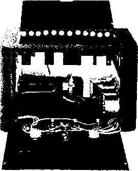 Figure 41 TRANSMITTER-RECEIVER CABINET, SHOWING POWER SUPPLY AND MODULATOR The power supply and modulator chassis are mounted vertically against the side walls of the cabinet. The tubes are mounted on the top edge of the chassis. A small blower motor is placed at the rear of the chassis for continuous duty operation. R-f section sits upon power transformer and is held in position by panel bolts and sheet metal screws passed through rear of cabinet. 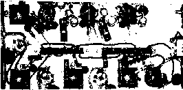 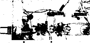 drives a second 12AT7 tripler stage to 224-6 Mc. All stages employ capacity coupling. A third 12AT7 (Vn) is used as a push-pull neutralized amphfier at 224.6 Mc. The plate circuit of this stage is a hair pin Inductance (Ls) tuned by a miniature butterfly capacitor Св. Inductive coupling is employed between the driver stage (Vio) and the amplifier, and between the amplifier and the antenna circuit. A 1N34 germanium diode serves as a r-f voltmeter in the antenna circuit for transmitter tuning purposes. The transmitter modulator, audio tone oscillator, and receiver audio amplifier stage are mounted upon another chassis (figure 38). The modulator uses two tubes. A 12AU7 (Vu) serves as a two stage resistance coupled speech amplifier, and a 12AX7 (Vu) is used as a class В modulator. The speech amplifier is designed to be used with a mobile-type carbon microphone. M-c-w transmission is permissible in the 220 Mc. band and a 12AU7 (Vis) audio oscillator has been added for this purpose. The oscillator may be keyed for code transmissions. The power supply occupies the remaining chassis. It uses two 5Y3 rectifier tubes to provide 300 volts at a current drain of 210 milliamperes. No standby circuits are required since both transmitter and receiver operate simultaneously. Assembly The complete assembly Is hous-and Wiring ed in a steel cabinet measuring 7 x 12 X 8 (figures 34 and 36). The receiver and transmitter portions are built upon two aluminum chassis measuring 5 X 8 X 1 . These chassis are bolted together as seen in figures 39 and 40 and occupy the center section of the cabinet- The power supply and modulator are built upon two similar chassis that are mounted against the side walls of the cabinet as seen in figure 41. The corners of these chassis are rounded to permit mounting them snugly against the walls of the cabinet. The various tubes are mounted in a vertical position on the upper side of the chassis while the transformers mount on the vertical surface. To the rear of the cabinet is a small blower motor to provide adequate ventilation for protracted operation of the equipment. The various manual controls fasten directly to the main panel of the cabinet and flexible leads are run from them to their respective circuits in the equipment. The r-f deck sits atop the power transformer and the modulation transformer and is held in position by sheet metal screws that pass through the rear wall of the cabinet into the chassis. The Transmitter Chassis. The placement of major parts on the transmitter chassis may be seen in figures 39 and 40. The crystal oscillator stage is at the front of the chassis with the crystal mounted in a horizontal position, projecting through the front panel of the cabinet. The multiplier stages fall in a line, with the final amplifier stage at the rear of the chassis. The coaxial antenna receptacle Ji and antenna tuning capacitor Ct are mounted to the rear, wall of rhe chassis. Common v.h.f. wiring techniques are employed in the assembly. Short, direct leads in the r-f section are mandatory. The sockets of the two tripler tubes (Va and Vw) and the amplifier tube (Vn) are positioned at an angle of 45 degrees so that a line drawn through pins 1 and 6 is parallel with the front edge of the chassis. The midget butterfly capacitors are mounted in line with the tube sockets, permitting very short leads to be run from the plate pins of the tubes to the stators of the capacitors. The nine-pin tube sockets are the type that mount from beneath the chassis and have a metal ring encasing the phenolic portion of the socket. The various pins of each socket that must be grounded are bent down and soldered directly to this ring. The grid resistors of Vs and Vio are installed directly between the grid pins and the grounded cathode pins of the tube socket. The coupling capacitors between the stages are placed between the grid pins and the stator rods of the butterfly tuning capacitors. Filament pins 4 and 5 of the nine-pin sockets are grounded to the socket ring and a common filament lead runs between the number 9 pins. Inductors Ll and Ъ. are made of manufac- tured coil Stock and are mounted to the stator rods of the tuning capacitors. Coils La and Li may be wound from enameled wire. The various power leads, decoupling resistors and capacitors are placed clear of the r-f circuitry and the components are mounted upon phenolic tie point strips placed adjacent to the tube sockets. The power leads and meter leads that leave the chassis pass through ceramic feed through capacitors {Centralab FT-WOO) mounted on the walls of the chassis. Preliminary Transmitter Adjustments Transmitter operation may be checked using the power supply shown in figure 38, or any auxiliary supply capable of providing about 200 volts at 80 milliamperes. If the permanent supply is used for tune-up purposes, a 5000 ohm, 10-watt dropping resistor should be placed in series with the B-plus lead to the exciter to protect the tubes in case of misadjustments. Tuned circuit Li-Ci may be set to 25 Mc. with the aid of a grid dip oscillator and the 6AB4 oscillator tube and crystal Xi plugged in their sockets. Proper operation of this and succeeding stages may be checked with a 2 volt, 60 milliampere (pink bead) flash light bulb attached to a small loop of wire which is held in proximity to the coil of the stage being adjusted. When oscillation is obtained, the 12AT? tripler tube is plugged in its socket and circuit L2-C2 set to 75 Mc. with the grid dipper. Plate voltage is again applied and the circuits touched up for maximum bulb brilliance when the pickup loop is held near Ls. The second tripler tube Vio is plugged in the socket and circuit b-Ca adjusted for maximum output at 225 Mc. using the indicator lamp. Spacing of the turns of L.5 may require adjustment to permit resonance. Plate current drawn by these three tubes should be about 70 milliamperes when the dropping resistor is shorted out. The next step is to neutralize the amplifier stage. This may be done by observing the grid current of Vii while capacitors Ci and Cs are adjusted. The leads of a high resistance voltmeter are temporarily clipped across the 2.7K grid resistor of the amplifier stage, and the exciter circuits are repeaked for maximum grid voltage reading. Over twenty volts should be obtained. Plate voltage to the amplifier stage is removed for this test. Neutralizing capacitors Cl and Cs are now set to minimum capacity and coil Lj is varied in position with respect to L3 to obtain maximum grid voltage. The amplifier plate tuning capacitor Co is tuned through resonance while grid voltage is observed. If a change in voltage occurs during HANDBOOK 220-Mc. Duplex 603 the tuning process the settings of capacitors G and G are advanced in unison until no change of grid voltage is noticeable. As the capacity settings are increased (keeping the two settings approximately equal) the kick of grid voltage will gradually decrease, until there is either no movement of the meter as G is varied, or else merely a gradual rise of a volt or so as Ci is swung through its range. A 6.3 volt, 150 miiliampere (brown bead) lamp is now connected to antenna receptacle Jl and plate voltage is applied to the amplifier stage and exciter. Capacitors Ce and Ct are tuned for maximum bulb brilliance. The plate current of the amplifier stage will be close to 30 milliamperes under conditions of maximum output. Once initial adjustments have been made, a 0-1 d.c. milliammeter may be connected to the r-f voltmeter terminals and the transmitter may be completely tuned by adjusting all resonant circuits for maximum Indication of the meter. It Is wise, however, to make the preliminary adjustments stage by stage as described above to acquaint the operator with proper transmitter operation. The Receiver Chassis. The placement of the major components of the receiver chassis may be seen in figures 39 and 40. The line-up of stages forms a U on the chassis, passing down one side, across the front and back along the other side. Two six terminal phenolic tie-point strips are mounted along the center line of the chassis, supporting various decoupling and vohage dropping resistors. Layout of the r-f stages may be seen in the under-chassis view of figure 40. A small copper shield plate 1 high and 11/2 inches long passes across the center of each socket and is grounded at each end by soldering to the socket retaining screws. The center stud of the socket, and pins 1, 3, 4, 6, and 9 are all soldered to this plate. Tuning capacitors Cs, G, Сю, and Cn are mounted close to the tube sockets, and the VHF-type bypass capacitor at the cold end of each coil (Centralab type ZA) Is mounted next to the tuning capacitor. Coils Ls, L , Lm, and Ln are mounted between the terminals of the respective tuning capacitor and the adjacent VHF bypass capacitor. Care must be taken to keep the coil leads as short as possible-less than 14-Inch long in any case. One filament choke of each r-f amplifier stage is grounded to the shield plate and the Other choke is bypassed by a disc ceramic capacitor and returns to the common filament lead. Wiring of the i-f stages is straightforward. VERTICAL ARRAY FOR TRANSMISSLOM HORIZONTAL ARRAY FOR RECEPTION 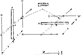 FEED SYSTEM FOR EACH ANTENNA U- 23. Ъ
COAX i AL BALUN TOTAL LENGTH - 17 1/4 MADE of Tin COAXIAL L 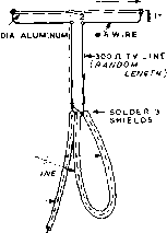 75 ft COAXIAL LINE - TO TRANSMITTER-RECEIVER Figure 42 DUAL ANTENNA SYSTEM FOR 220 MC. TRANSMITTER-RECEIVER The some polarizaiien must be used on each link. This meons thot po/orizotion of transmission and reception is different at each station. For the companion link to the one illustrated in this drawing, the vertical array should be used for reception, and the horizontal array tor transmission. components being mounted between the socket and If transformer terminals and the phenolic tie-point strip. Power leads are terminated at the six prong plug mounted on the rear apron of the chassis. No connection need be made between the r-f circuit of the transmitter and the mixer stage of the receiver as ample proximity coupling exists. In fact, a shield plate is placed over the bottom of the transmitter chassis to reduce the mixer injeclon to a tolerable level. Preliminary Receiver Adjustment. After all wiring is completed, the i-f section of the receiver may be aligned. A 4.5 Mc tone modulated signal is loosely coupled to the plate pin (#5) of mixer tube Vj and earphones or an a-c meter connected to the output circuit of audio tube V; (Pins 5 and 6 of the power plug). The slug cores of transformers Ti, Ta, Ъ, and Tt are adjusted for maximum signal. The receiver and transmitter sections should be bolted together and the transmitter tuned  up wih а dummy load- This will provide in-jecion signal for proper receiver operation at 220.1 Mc. A remote signal (preferably that of the companion unit) should be used as a signal source and the tuned circuits of the r-f amplifiers adjusted for best signal reception. It may be necessary to alter the spacing of coils Ls - Lii to provide proper circuit resonance which should occur at about the middle of the tuning range of the associated capacitor. Modulator and Power Supply Construction. The layout of the modulator and power supply can be seen in figure 41. The units are wired and the control leads are brought out through insulated grommets placed in the end of the chassis. A common ground lead is run from each chassis to the switches and controls mounted upon the front panel. The small blower motor is mounted at the rear of the cabinet and a row of ventilation holes is drilled around the top edge of the cabinet as shown in the photograph. The power supply and modulator should be tested before they are mounted in the cabinet, and the whole assembly should be in operating condition before it is placed within the cabinet. The tone of the audio oscillator (Vis) may be varied by placing a capacitor across the primary winding of the oscillator transformer Ts. Antenno Two separate antennas are re- Installotion quired for duplex operation. To reduce coupling, one link is horizontally polarized and the other link is vertically polarized as illustrated in figure 42. Care must be taken that identical polarization is employed at both ends of each link. Three-element beam antennas are used for each link. A folded dipole and balun system are employed to provide a good match to the coaxial transmission line. After the links have been set up, transmitter and receiver tuning adjustments should be peaked to maximize the signals. It will be found advantageous to experiment with Figure 43 COMPACT VFO PROVIDES HIGH STABILITY SIGNAL FOR HIGH FREQUENCY DX BANDS This smaW v.f.o. employs latest techniques to achieve stable, drift-free signal. Only УУг X 9 X 7 in size, the unit uses a high~C 1.75 Mc. oscillator followed by a cathode follower to achieve a maximum degree of circuit isolation. Buffer tuning and control switch are at left of panel, with large, easily read frequency control dial at center. the position of the antennas to provide maximum signal pickup with a minimum of interference from the local transmitter. In general, the receiver antenna should be oriented for maximum signal from the distant station, and the transmitter antenna should be oriented for minimum local signal pickup. For general use, the two antennas may be attached to the same supporting structure, separated from each other by four or five feet. As with any VHF equipment, time spent in placing the antennas will pay big dividends in system operation. 28-6 A High Stability V.F.O, For the DX Operator Stability and freedom from drift are the prime requisites of a high quality variable frequency oscillator. To meet the requirements of the discriminating operator the v.f.o. must be stable with respect to warm-up, ambient temperature variations, line voltage shift, vibration, and the presence of a strong r-f field. To achieve these parameters in a unit simple enough for home construction is a large order. The variable frequency oscillator shown in figures 43, 46, and 47 is a successful attempt to meet these requirements and is recommended to those operators who desire a v.f.o. having a high order of stability and resetability. Frequency The perfect variable frequency Stability oscillator has the frequency determining elements completely VOLTAGE MEASUREMENTS, V.F.O. SCREEN (PIN3) eue-70 CATHODE (PINB) eue- 10.5 R-F VOLTS, GRID (PIN9) вив- 10.3 R-P VOLTS, CATHODE (РШ в) 6Ue- 9.5 R-f VOLTS, j1, ACROSS 47 OHM RESISTOR -6.2 Figure 44 VOLTAGE CHART FOR V.F.O. (/eo>) Ll -6U8
.01 L .oi L NOTES; -AU MICA CAPACITORS EL-MENCO SILVER MICA OR EQUIVALENT. г-ALL CERAMIC CAPACITORS DISC-ТУРЕ CENTRALAB OD OR EQUIVALENT. Iq p ZERO BEAT J..01 6AQ5 20 M Lz о ± ± j£ о о о ° RFC1 с  хм1г .005 RFC2e 005 С .005 .-)1-Й^6А0 5 .005 ,005 RFC2e
iBi-гоо) f CONTROL ) Figure 45 Ci-.002 iifd. Centralab high accuracy capacitor 950-202. Сг-300 tinfd. Bud MC-J860 Cl-25 iiuifd. Bud LC-1642 Ll-77% turns #20 e, З/4 diam., approx. I long. (See text) Wind on national ceramic form XR- at 4 turns from cold end. Ll-4.5 Mc. Interstage TV transformer. J. W. Mi er 1466. Remove secondory winding and with В turns it 22 d.c.c. wound next to primary winding. RFC, 2.5 mh. National R-700 RFC<-VHF choke, 500 ma. National R-60 R-F OUTPUT 72. Гор replace isolated both electrically and physically from the rest of the transmitting equipment. This goal cannot be achieved in practice since a vacuum tube or transistor must be coupled to these circuit elements to maintain oscillation. The coupling of such items deteriorates the electrical isolation of the frequency determining circuit. By the use of proper coupling circuits the effects of the tube or transistor can be minimized- The frequency determining circuit is also. subject to temperature variations, changes in the relative humidity of the surrounding air, and absorption of heat from nearby objects. By employing temperature and humidity resistive materials and removing as many heat generating components from the vicinity of the frequency determining circuits, a good degree of stability in the v-f.o- may be obtained. Finally, steps must be taken to ensure that the oscillator of the v.f.o. unit is completely free of parasitics, and that the output waveform Figure 46 REAR VIEW OF V.F.O. CHASSIS, SHOWING PLACEMENT OF PARTS Oscillator inductor Li is at the left of chassis, separated from the heat producing electron tubes. To right of L, is the precision padding capacitor Ct mounted to the chassis. The main tuning capacitor is firmly affixed to a heavy dural mounting plate bolted to the gear box of the dial drive. The rear of the tuning capacitor is attached to the chossis by a mounting stud. To the right are the three tubes and the output transfermer. Directly under the tuning capacitor is the polystyrene chassis plate holding the feed through bushings for the oscillator leads to the under-chassis area. Control switch Sl is at upper right.  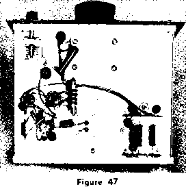 UNDER-CHASSIS VIEW OF V.F.O. UNIT Power lead filters are at lower right of chassis, with r-f circuit components at left. All parts are firmly mounted to terminals and tie points to reduce vibration. Power leads are laced. Buffer tuning capacitor Сз is at upper left. is low in harmonic content. The variable frequency exciter to be described in this section meets these fundamental requirements. The V.F.O. Circuit The circuit diagram of the high stability v.f.o. is shown in figure 45, and the complete physical layout may be seen in figures 46 and 47. The pentode section of a miniature 6U8 tube is used as the oscillator. The oscillator circuit is tuned to the 160 meter region and consists of a high-Q oscillator coil resonated to the working frequency by a precision ceramic capacitor in parallel with a variable air capacitor. The ceramic capacitor (Centrdab type 950) has a measured temperature coefficient of less than plus or minus ten parts per million over the temperature range of -40 degrees to plus 60 degrees Centigrade. The use of ordinary ceramic or silver mica capacitors as a substitute for this unit is not recommended, since the temperature coefficient of such units cannot be closely controlled in quantity production. The oscillator coil, Li, is wound upon a ceramic coil form that has a very low coefficient of expansion. The coil turns are spaced to ensure low inter-turn capacitance. The wire is wound upon the form under tension and at a relatively high temperature. As the wire cools, it shrinks and tightly clasps the form so that for all practical purposes the wire and the form have the same coefficient of expansion with regard to temperature changes. This style of winding reduces the possibihty of the oscillator developing random frequency jumps with changes in temperature and humidity. A 56 ohm resistor is inserted in series with the grid lead of the 6U8 oscillator tube. This suppressor eliminates any tendency toward parasitic oscillation that can result in this type of oscillator circuit. The parastic tends to make fundamenal oscillation unstable at certain settings of the oscillator tuning capacitor. This instability may be caused by variations of the inherent inductance of the tuning capacitor at the frequency of parasitic oscillation. All components of the oscillator circuit are spaced clear of the oscillator tube to prevent heat transfer from the tube to the frequency determining circuit. The pentode oscillator is R-C coupled to the triode section of the 6U8 which serves as a cathode follower. The input impedance of the cathode follower is extremely high and provides excellent isolation between the oscillator circuit and the output stage. Plate and screen voltage of the oscillator and plate voltage of the cathode follower are regulated by an OA2 gas regulator to provide maximum isolation from power supply fluctuations. The r-f output of the triode section of the 6U8 is taken from the low impedance cathode circuit and is capacity coupled to a 6AQ5 miniature pentode tube which serves as a frequency doubler to the 80 meter region. The v.f.o. covers the frequency range of 1750 kc. to 1850 kc, and the plate circuit of the 6AQ5 doubler tunes 3500 kc. to 3700 kc. The 80 meter output is 0-8 watt which is more than sufficient to drive a tetrode buffer such as an 807 or 6146. If more output is desired, a 6CL6 may be substituted for the 6AQ5 (with appropriate socket wiring changes) to deliver approximately 2 watts. One filament terminal of each tube is grounded and the free terminals are bypassed to ground with .005 /Ltfd. ceramic capacitors. The filament leads then pass through an r-f choke to ensure maximum lead isolation. Switch Si disables the v.f.o. by removing the plate voltage. A second section of the switch opens an auxiliary circuit that can control the power relays of the transmitter. A third position of switch Si permits the v.f.o. to be turned on by itself for zero-beat operation. Transmitter keying for c-w operation is done in the stages following the v.f-o.-exciter to achieve maximum frequency stability and freedom from frequency shift during keying. Mechanicol Design The mechanical design of the V.F.O. of the variable frequen- cy oscillator is equally important as the electrical design if maximum stability and reliability are to be achieved. Provision must be made for dissipation of the heat generated by the vacuum tubes, and the v.f.o. components should be mounted on a sheet of conducting material which will act as a heat sink and will tend to resist rapid changes in the temperature of the components bolted thereto. The v.f.o. is built upon a cadmium plated steel chassis measuring 71/2 x 9 x 1V2 - The gear box of the National Hi?0-type dial is bolted to the chassis and the main tuning capacitor C2 is affixed by its front bearing to a 3 x 3 x 0.125 dural plate held to the capacitor gear box by three long machine screws and three li/s metal spacers. The tuning capacitor is driven through a high quality flexible coupling. This coupling should be free of back-lash, and should not permit end pressure on the shaft of the capacitor. A Johnson 104-250 coupling is recommended. Make sure that the shaft of the gear box and that of the capacitor are perfectly in line as misalignment tends to force a degree of back-lash in the system. The rear mounting foot of the capacitor is fastened to the steel chassis by means of a long 6/32 bolt and a 1-inch metal spacer. This assembly provides a very rugged arrangement with a minimum of flexing between the capacitor and the chassis. Oscillator coil Li and the precision ceramic capacitor Ci are mounted to the chassis to the side of the tuning capacitor as seen in the rear view photograph. The slug of coil Li is removed and discarded before the coil is wound. Moveable oscillator slugs are not conducive to any great degree of oscillator stability and this potential source of instability should be taken from the circuit before it can do any damage. The leads from the oscillator circuit to the 6U8 pentode tube pass through a IV4 hole cut in the steel chassis. A V -thick square of polystyrene is mounted under this hole and two miniature feedthrough bushings are mounted in the insulating plate. The residual capacity to grounds of these important leads is thereby held to an absolute minimum value- The vacuum tubes and auxiliary circuits are placed on the opposite side of the tuning capacitor from the sensitive tuned circuit Li-Ci. In front of the oscillator tube is the 80 meter output coil b, the 6AQ5 socket and the OA2 socket. Switch Si is mounted to the front panel directly in front of the 6AQ5. The front panel is held to the chassis by means of four 6/32 bolts placed in the extreme corners of the front lip of the chassis. The panel is spaced slightly away from the chassis by an extra set of nuts slipped over the bolts before the panel is affixed to the chassis. All control leads to the v.f.o. unit pass through a four wire cable which enters the under chassis area via a rubber grommet on the back lip of the chassis. Each lead is bypassed with a .005 /ifd. ceramic capacitor and is filtered with a low resistance r-f choke. The coaxial output receptacle for the v.f.o- is also mounted on the rear lip of the chassis, directly behind the 6U8 oscillator tube. Wiring the V.F.O. The under-chassis area of the v.f.o. should be wired first. Common ground connections are made to the three sockets by means of soldering lugs and lock washers placed beneath one socket retaining nut. The filament leads are wired next. The bypass capacitors for pins 1, 3, and 4 of the 6U8 socket are placed between the socket pins and the grounded center stud of the socket with the shortest possible leads. All components of the 6U8 stage should be mounted solidly in place between adjacent tube pins or to nearby phenolic tie-point terminals. The grid resistor and capacitor of the oscillator section are mounted between pin #2 of the 6U8 socket and the inter-chassis feedthrough insulator in the polystyrene block. The plate coil of the 6AQ5 doubler stage is made from a 4.5 Mc. sound TV i-f transformer-The secondary winding and tuning capacitor are removed and a link winding of 8 turns is wound on the form, closely spaced to the primary winding. The transformer is then replaced in the shield can and mounted atop the chassis. The r-f choke in the plate circuit of the doubler stage is mounted between two terminals of a phenolic tie-point strip bolted to one of the transformer lugs. The power supply r-f filter circuits are placed on two four terminal tie-point strips mounted in the far corner of the chassis. The bypass capacitors are mounted between the individual terminal lugs and the adjacent ground connections of the strip and the r-f chokes are mounted between the strips. After the under-chassis wiring is completed the wiring atop the chassis may be done. The leads of the tuned circuit are made of #12 tinned wire. The coil is wound with #20 enameled wire space-wound to a length of approximately one inch. The easiest way to ob-tam the correct spacing is to wind two separate windings on the coil. One winding is the desired one of #20 wire, the second is composed of #24 enameled wire and is used only for spacing. The two windings are put on simultaneously and the #24 wire is removed after the other winding has been properly terminated at both ends. To obtain the best temperature coefficient of the coil the wire should be wound on when it is warm. The easiest way to accomplish this is to place rolls of the two wire sizes in the open and warm them slowly until they are almost too hot to touch. The wires are then removed from the oven and wound on the coil form before they have a chance to cool to room temperature. The wire is kept under tension during the winding process and may be reheated with a soldering iron or heat lamp if it begins to grow cold. When the coil is completed and the wire cools, it will be found to be tightly wound around the coil. After the coil has been completed the fourth turn (cathode tap) should be cleaned carefully with a small, sharp knife blade and a short length of #22 wire is soldered to the turn. The opposite end of this lead is attached to a lug terminal at the base of the coil. All the unused lugs may then be removed from the coil form. A separate ground lead is run from the ground lug of the coil form to the ground lug of Cl and then to the rotor terminal of tuning capacitor Сг to prevent any intermittent ground paths through the chassis and the capacitor mounting assembly. V.F.O. Power The schematic of the v.f.o. Supply power supply is shown in figure 48. The power supply is constructed as a separate unit since it is desired to keep the heat and vibration of the transformers and chokes away from the v.f.o. circuits. The power construction is straightforward, with all leads bypassed to prevent r-f pickup from the transmitter. The supply is built upon a 1у2 X bvi miniature amplifier foundation chassis and provides 300 volts at 50 milliamperes for the v.f.o. circuits. V.F.O. Alignment and Adjustment After the v.f.o. wiring has been checked the 6U8 and OA2 tubes should be plugged in their sockets. Switch Si is set to the off position and the power supply is turned on. The filaments of the tubes should light, and when Si is set to either the  .01 J..01 с - с 115 V. 5V4-G aojjft У Ш> I tOB. ILzojufJi i L.oi 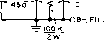 ofil,6.sv. Figure 48 SCHEMATIC, POWER SUPPLY FOR VFO Ti-32S-0-325 volts, 55 ma. Stoneor PC-8407 CHi, CH7 lienry at 50 ma. Stancor C-1707 zero-beat or transmit position the v.f.o. signal may be heard in a nearby receiver tuned to the 160 meter region. The oscillator is now run for a few hours before it is adjusted to the correct frequency range. The next step is to plug the 6AQ5 in its socket, and a 6.3 volt, 150 ma. (brown bead) pilot lamp is placed across the terminals of the coaxial output jack Jl, serving as a dummy load. The v.f.o. is turned on and the setting of Сз and the slug of coil L2 are varied to provide an indication in the bulb. The next step is to calibrate the oscillator. A BC-221 frequency meter or calibrated receiver should be used. The dial of the v.f.o. should be set so the bandspread scale reads 0 when capacitor C2 is fully meshed. When the dial is tuned to a reading of 10 the capacitor is nearly fully meshed, and the operating frequency of the oscillator should be 3500.00 kc. Unless you are extremely lucky, this will not be the case. Since there are no adjustable padding capacitors in the frequency determining circuit coil Ll must be adjusted a bit at a time until the correct frequency falls at the designated dial reading. The turns of Li may be varied in position with the aid of a pen-knife blade, and minute adjustments to the top few turns may be made until the correct calibration is reached- Once the calibration of the oscillator has been set, the turns of Li may be permanently fixed in place by means of a few drops of colorless nail polish. Use the minimum amount of polish possible. Placing the polish on the coil will vary the operating frequency slightly, so a final slight adjustment must be made after the last spot of polish has been placed on the coil. Full coverage of all the amateur bands except 80 meters will be obtained with this value of tuning capacitor. Decreasing the size of C2 will provide greater bandspread on the high frequency bands, and increasing the capacitance of G will provide full coverage of the 80 meter band. In either case, it will be necessary to juggle the turns on Ll to obtain the correct tuning range. Operoting Check When completed the v.f.o. of the V.F.O. should be placed in the operating position and run for a period of several hours. During this time, the frequency of the v.f.o. should be compared against a known standard such as a 100 kc. crystal, or Standard Frequency Station WWV. Under normal conditions the v.f.o. will have a small positive initial warm-up drift of less than 100 cycles on 80 meters. It should settle down after a period of time and remain relatively stable if the temperature of the room is constant. Temperature stabilization may be accomplished by the addition of a small value of negative coefficient capacitance to the tuning circuit. This is a cut-and-try process and is not recommended unless the builder has plenty of time and previous experience with the task. It is not really required unless the oscillator is operated under extremes of room temperature. The last step is to place the v,f.o. in the metal cabinet. The unit should not be operated out of the cabinet as the enclosure affords some degree of shielding from the r-f field of the transmitter. The rear of the chassis is fastened to the bottom of the cabinet by two sheet metal screws passed from the under side of the bottom of the cabinet up into the rear lip of the chassis- To prevent frequency changes during operation the lid of the cabinet should be fastened shut by means of two sheet metal screws run through the front corners of the lid into the cabinet. CHAPTER TWENTY-NINE 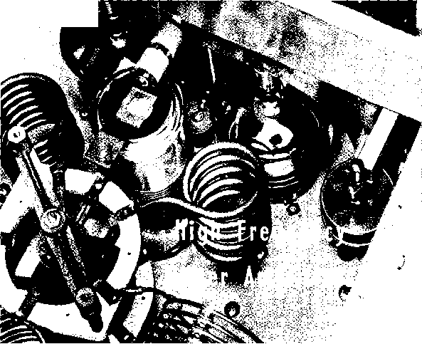 The trend in design of transmitters for operation on the high frequency bands is toward the use of a single high-level stage. The most common and most flexible arrangement includes a compact bandswitching exciter unit, with 15 to 100 watts output on all the high-frequency bands, followed by a single power amplifier stage. In many cases the exciter unit is placed upon the operating table, with a coaxial cable feeding the drive to the power amplifier, although some operators prefer to have the exciter unit included in the main transmitter housing. This trend is a natural outgrowth of the increasing importance of v-f-o operation on the amateur bands. It is not practical to make a quick change in the operating frequency of a transmitter when a whole suxxession of stages must be returned to resonance following the frequency change. Another significant factor in implementing the trend has been the wide acceptance of commercially produced 75 and 150-watt transmitters. These units provide r-f excitation and audio driving power for high-level amplifiers running up to the 1000-watt power limit. The amplifiers shown in this chapter may be easily driven by such exciters. 29-1 Power Amplifier Design Choice of Either tetrode or triode tubes may Tubes be used in high-frequency power amplifiers. The choice is usually dependent upon the amount of driving power that is available for the power amplifier. If a transmitter-exciter of 100-watt power capability is at hand (such as the Heath TX-1) it would be wise to employ a power amplifier whose grid driving requirements fall in the same range as the output power of the exciter. Triode tubes running 1-kilowatt input (plate modulated) generally require some 50 to 80 watts of grid driving power. Such a requirement is easily met by the output level of the 100-watt transmitter which should 1 ... 57 58 59 60 61 62 63 ... 80 |
||||||||||||||||||||||||||||||||||||||||||||||||||
|
© 2026 AutoElektrix.ru
Частичное копирование материалов разрешено при условии активной ссылки |