 |
 |
 |
| Главная Журналы Популярное Audi - почему их так назвали? Как появилась марка Bmw? Откуда появился Lexus? Достижения и устремления Mercedes-Benz Первые модели Chevrolet Электромобиль Nissan Leaf |
Главная » Журналы » Simple coaxial reflectometer 1 ... 58 59 60 61 62 63 64 ... 80 Design 611 то ANTENNA CIRCUIT TO ANTENNA CIRCUIT 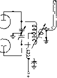 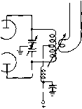 UNBALANCED COAXIAL FEED SYSTEM BALANCED TWiN-LINE FEED SYSTEM Figure 1 LINK COUPLED OUTPUT CIRCUITS FOR PUSH-PULL AMPLIFIERS be employed as the exciter. Tetrode tubes (such as the 4-250A) require only 10 to 15 watts of actual drive from the exciter for proper operation of the amplifier stage at 1-kilowatt input. This means that the output from the 100-watt transmitter has to be cut down to the 15 watt driving level. This is a nuisance, as it requires the addition of swamping resistors to the output circuit of the transmitter-exciter. The triode tubes, therefore, would lend themselves to a much more convenient driving arrangement than would the tetrode tubes, simply because their grid drive requirements fall within the power output range of the exciter unit. On the other hand, if the transmitter-exciter output level is of the order of 15 - 40 watts (the Johnson Ranger, for example) sufficient drive for triode tubes running 1-kilowatt input would be lacking. Tetrode tubes requiring low grid driving power would have to be employed in a high-level stage, or smaller triode tubes requiring modest grid drive and running 250 watts or so would have to be used. Power Amplifier Design-Choice of Circuits Either push-pull or single ended circuits may be employed in the power amplifier. Using modern tubes and properly designed circuits, either type is capable of high efficiency operation and low harmonic output. Push-pull circuits, whether using triode or tetrode tubes usually employ link coupling between the amplifier stage and the feed line running to the antenna or the antenna tuner. It is possible to use the link circuit in either an unbalanced or balanced configuration, as shown in figure 1, using unbalanced coaxial line, or balanced twin-line. 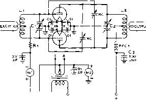 -0 6+ 6 BIAS 110 V. Figure 2 CONVENTIONAL PUSH-PULL AMPLIFIER CIRCUIT The mechanical layout should be symmetrical and the output coupling provision must be evenly balanced with respect to the plate coil Cl-Approx. 1.5 fififd. per meter of wavelength per section Cl-Refer to plate tank capacitor design in Chapter 11 C-May be SOO fintd., 10,000-volt type ceramic capacitor NC-Max. usable capacitance should be greater, and min. capacitance less than rated grid-plate capacity of tubes in amplifier. 50% greater air gap than Сг. Rl-700 ohms, 20 wotts. This resistor serves as low Q r-f choke. RFC)-All-band r-f choke suitable for plate current of tubes Mi-Mi-Suitable meters for d-c grid and plate currents All low voltage .001 jifd. and .01 /ifd. by-pass capacitors are ceramic disc units (Centralab DD or eqaiv.) Ll-50-wott plug-in coil, center link Ll-Plug-in coil, center link, of suitable power rating. G>mmon technique is to employ plug-in plate coils with the push-pull amplifier stage. This necessitates some kind of opening for coil changing purposes in the electrically tight enclosure surrounding the amplifier stage. Gare must be used in the design and construaion of the door for this opening or leakage of harmonics through the opening will result, with the attendant TVI problems. Single ended amplifiers may also employ link-coupled output devices, although the trend is to use pi-network circuits in conjunction with single ended tetrode stages. A tapped or otherwise variable tank coil may be used which is adjustable from the front panel, eliminating the necessity of plug-in coils and openings into the shielded enclosure of the amplifier. Pi-network circuits are becoming increasingly popular as coaxial feed systems are coming Into use to couple the output circuits of transmitters directly to the antenna. 29-2 Push-Pull Triode Amplifiers Figure 2 siiows a basic push-pull triode amplifier circuit. While variations in the method of applying plate and filament voltages and bias are sometimes found, the basic circuit remains the same in all amplifiers. Filament Supply The amplifier filament transformer should be placed right on the amplifier chassis in close proximity to the tubes. Short filament leads are necessary to prevent excessive voltage drop in the connecting leads, and also to prevent r-f pickup in the filament circuit. Long filament leads can often induce instability in an otherwise stable amplifier circuit, especially if the leads are exposed to the radiated field of the plate circuit of the amplifier stage. The filament voltage should be the correct value specified by the tube manufacturer when measured at the tube sockets. A filament transformer having a tapped primary often will be found useful in adjusting the filament voltage. When there is a choice of having the filament voltage slightly higher or slightly lower than normal, the higher voltage is preferable. If the amplifier is to be overloaded, a filament voltage slightly higher than the rated value will give greater tube life. Filament bypass capacitors should be low internal inductance units of approximately .01 /xfd. A separate capacitor should be used for each socket terminal. Lower values of capacitance should be avoided to prevent spurious resonances in the internal filament structure of the tube. Use heavy, shielded filament leads for low voltage drop and maximum circuit isolation. Plate Feed The series plate voltage feed shown in figure 2 is the most satisfactory method for push-pull stages. This method of feed puts high voltage on the plate tank coil, but since the r-f voltage on the coil is in itself sufficient reason for protecting the coil from accidental bodily contact, no additional protective arrangements are made necessary by the use of series feed. The insulation in the plate supply circuit should be adequate for the voltages encountered. In general, the insulation should be rated to withstand at least four times the maximum d-c plate voltage. For safety, the plate meter should be placed in the cathode return lead, since there is danger of voltage breakdown between a metal panel and the meter movement at plate voltages much higher than one thousand. Grid Bias The recommended method of obtaining bias for c-w or plate modulated telephony is to use just sufficient fixed bias to protect the tubes in the event of excitation failure, and to obtain the rest by the voltage drop caused by flow of rectified grid current through a grid resistor. If desired, the bias supply may be omitted for telephony if an overload relay is incorporated in the plate circuit of the amplifier, the relay being adjusted to trip immediately when excitation is removed from the stage. The grid resistor Ri serves effectively as an r-f choke in the grid circuit because the impressed r-f voltage is low, and the Q of the resistor is poor. No r-f choke need be used in the grid bias return lead of the amplifier, other than those necessary for harmonic suppression. The bias supply may be built upon the amplifier chassis if care is taken to prevent r-f from finding its way into the supply. Ample shielding and lead filtering must be employed for sufficient isolation. The Grid Circuit As the power in the grid circuit is much lower than in the plate circuit, it is customary to use a close-spaced split-stator grid capacitor with sufficient capacitance for operation on the lowest frequency band. A physically small capacitor has a greater ratio of maximum to minimum capacitance, and it is possible to obtain a unit that will be satisfaaory on all bands from 10 to 80 meters without the need for auxiliary padding capacitors. The rotor of the grid capacitor is grounded, simplifying mounting of the capacitor and providing circuit balance and electrical symmetry. Grounding the rotor also helps to retard v-h-f parasitics by by-passing them to ground in the grid circuit. The L/C ratio in the grid circuit should be fairly low, and care should be taken that circuit resonance is not reached with the grid capacitor at minimum capacitance. That is a direct invitation for instability and parasitic oscillations in the stage. The grid coil may be wound of no. 14 wire for driving powers of up to 100 watts. To restrict the field and thus aid in neutralizing, the grid coil should be physically no larger than absolutely necessary. Circuit Layout The most impomnt consideration in constructing a push-pull amplifier is to maintain elearical symmetry on both sides of the balanced cir- HANDBOOK Design 613 cuit. Of utmost importance in maintaining electrical balance is the control of stray capacitance between each side of the circuit and ground. Large masses of metal placed near one side of the grid or plate circuits can cause serious unbalance, especially at the higher frequencies, where the tank capacitance between one side of the tuned circuit and ground is often quite small in itself. Capacitive unbalance most often occurs when a plate or grid coil is located with one of its ends close to a metal panel. The solution to this difficulty is to mount the coil parallel to the panel to make the capacitance to ground equal from each end of the coil, or to place a grounded piece of metal opposite the free end of the coil to accomplish a capacity balance. Whenever possible, the grid and plate coils should be mounted at right angles to each other, and should be separated far enough apart to reduce coupling between them to a minimum. Coupling between the grid and plate coils will tend to make neutralization frequency sensitive, and it will be necessary to readjust the neutralizing capacitors of the stage when changing bands. All r-f leads should be made as short and direct as possible. The leads from the tube grids or plates should be connected directly to their respective tank capacitors, and the leads between the rank capacitors and coils should be as heavy as the wire that is used in the coils themselves. Plate and grid leads to the tubes may be made of flexible tinned braid or flat copper strip. Neutralizing leads should run directly to the tube grids and plates and should be separate from the grid and plate leads to the tank circuits. Having a portion of the plate or grid connections to their tank circuits serve as part of a neutralizing lead can often result in amplifier instability at certain operating frequencies. Excitation In general it may be stated Requirements that the overall power requirement for grid circuit excitation to a push-pull triode amplifier is approximately 10 per cent of the amount of the power output of the stage. Tetrodes require about 1 per cent to 3 percent excitation, referred to the power output of the stage. Excessive excitation to pentodes or tetrodes will often result in reduced power output and efficiency. Push-Pull Symmetry is the secret of suc- Amplifier cessful amplifier design. Shown Construction in figure 3 is the top view of a 350 watt push-pull all band 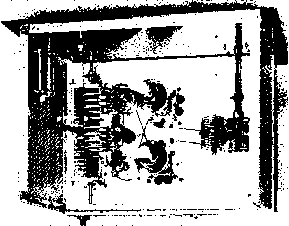 Figure 3 LAYOUT OF 350-WATT PUSH-PULL TRIODE AMPLIFIER Two S11-A tubes are employed in this circuit. Plate tuning capacitor is at leit ot chassis, with swinginglink type plag-in coil assembly mounted above it. Rotor ot split-stator capacitor may be insulated from ground to increase voltage breakdown rating of capacitor. Note thot pickup link is series-tuned to reduce circuit reactance. One corner af rotor plate of series capacitor is bent so that capacitor shorts itself out at maximum capacitance. Grid circuit coil and capacitor are at right. Center-linked plug-in coil is employed. Parasitic chokes are placed in grid leads adjacent to the tube sockets, and tube filaments are bypassed to ground with .01 fifd. ceramic capacitors. Complete area above the chassis is enclosed with perforated screen to reduce radiation ot r.f. energy. amplifier employing 811-A tubes. The circuit corresponds to that shown in figure 2 except that the 811-As are zero bias tubes. The bias terminals of the circuit are therefore jumpered together and no external bias supply is required at plate potentials less than 1300 volts. All r-f components are mounted above deck. The plate circuit tuning capacitor and swinging link tank coil are to the left, with the two disc-type neutralizing capacitors between the tank circuit and the tubes. At the right of the chassis is the grid tank circuit. Small parasitic chokes may be seen between the tube sockets and the grid circuit. Plate and grid meters are placed in the under-chassis area where they are shielded from the r-f field of the amplifier. Larger triode tubes such as the 810 and 8000 make excellent r-f amplifiers at the kilowatt level, but care must be taken in amplifier layout as the inter-electrode capacitance of these tubes is quite high. One tube and one neutralizing capacitor is placed on each side of the tank circuit (figures 4 and 5) to permit very short interconnecting leads. The relative position of the tubes and capacitors is trans- 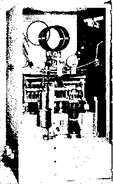 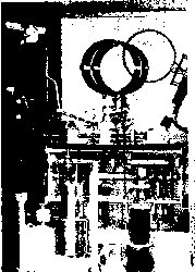 Figure 4 UNIQUE CHASSIS LAYOUT PERMITS SHORT LEADS IN KILOWATT AMPLIFIER Large size components required for high level amplifier often complicate amplifier layout. In this design, the plate tank capacitor sits astride small chassis running lengthwise on main chassis. Inductor is mounted to phenolic plate atop capacitor. Variable link is panel driven through right-angle gear drive. Plate circuit is grounded by safety arm when panel door is opened. Note that plate capacitor is mounted on four TV-type capacitors which serve to bypass unit, and also act as supports. A small parasitic choke is visible next to the grid terminal of the 810 tube. posed on each side of the chassis, as shown in the illustrations. The plate tank coil is mounted parallel to the front panel of the amplifier on a phenolic plate supported by the tuning capacitor which sits atop a small chassis-type box. The grid circuit tuning capacitor is located within this box, as seen in figure 6. An external bias supply is required for proper amplifier operation. Operating voltages may be determined from the instruction sheets for the particular tube to be employed. Whenever the amplifier enclosure requires a panel door for coil changing access it is wise to place a power interlock on the door that will turn off the high voltage supply whenever the door is open! Figure 5 LEFT-HAND VIEW OF KILOWATT AMPLIFIER OF FIGURE 4 Above shielded meter box is the protective micro-switch which opens the primary power circuit when ihe panel door is not closed. Tube sockets are recessed in the chassis so that top of tube socket shells are about /2-inch above chassis level. On right side of amplifier (facing it from the rear) the tube socket is nearest the panel, with the neutralizing capacitor behind it. On the opposite side, the capacitor is nearest the panel with the tube directly behind it. This layout transposition produces very short neutralizing leads, since connections may be made through the stator of plate tuning capacitor. 29-3 Push-Pull Tet-rode Amplifiers Tetrode tubes may be employed in push-pull amplifiers, although the modern trend is to parallel operation of these tubes. A typical circuit for push-pull operation is shown in figure 7. The remarks concerning the filament supply, plate feed, and grid bias in Section 29-2 apply equally to tetrode stages. Because of the high circuit gain of the tetrode amplifier, extreme care must be taken to limit interstage feedback to an absolute minimum. Many amateurs have had bad luck with tetrode tubes and have been plagued with parasitics and spurious oscillations. It must be remembered wirh high gain tubes of this type EXCITATION 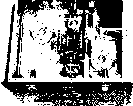 Figure 6 UNDER CHASSIS VIEW OF 1-KILOWATT TRIODE AMPLIFIER rhe nd circuit tuning capacitor and piate circuit r-f choke ore contained in the below chossis enclosure formed by a small chassis mounted at right angles to the front panel. The bandswitch coil assembly for the grid circuit is mounted on two brackets above this cutout. A metal screen attached to the bottom of the amplifier completes the TVI-proof enclosure. that almost full output can be obtained with practically zero grid excitation. Any minute amount of energy fed back from the plate circuit to the grid circuit can cause instabihty or oscillation. Unless suitable precautions are incorporated in the electrical and mechanical design of the amplifier, this energy feedback will inevitably occur. Fortunately these precautions are simple. The grid and filament circuits must be isolated from the plate circuit. This is done by placing these circuits in an electrically tight box. All leads departing from this box are by-passed and filtered so that no r energy can pass along the leads into the box. This restricts the energy leakage path between the plate and grid circuits to the residual plate-to-grid capacity of the tetrode tubes. This capacity is of the order of 0.25 \i\xiA. per tube, and under normal conditions is sufficient to produce a highly regenerative condition in the amplifier. Whether or not the amplifier will actually break into oscillation is dependent upon circuit losses and residual lead inductance of the stage. Suffice to say that unless the tubes are actually neu-trali2ed a condition exists that will lead to circuit instability and oscillation under certain operating conditions. With luck, and a .001 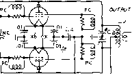 О -i- о -B1AS+ X X lOOS 5KV h b 1 1S V. о RFC 1 Figure 7 CONVENTIONAL PUSH-PULL TETRODE AMPLIFIER CIRCUIT Push-pull amplifier uses many of the same components required by triode tubes (see figure 2). Screen supply is also required. В-Blower for filament seals of tubes. C(-Low internal inductance capacitor, .001 lifd., SKV. Centralab type aSBS - 1000. NC-See fexf ond figure 8. PC-Parasitic choke. 50 ohm, 2-waft composition resistor wound with 3 turns # 72 e. wire. Note: Strap multiple screen terminals together at socket with % copper ribbon. Attach PC to center ot strap. heavily loaded plate circuit, one might be able to use an un-neutralized push-pull tetrode amplifier stage and suffer no ill effects from the residual grid-plate feedback of the tubes. In fact, a minute amount of external feedback in the power leads to the amplifier may just (by chance) cancel out the inherent feedback of the amplifier circuit. Such a condition, however, results in an amplifier that is not re-produceable. There is no guarantee that a duplicate amplifier will perform in the same, stable manner. This is the one, great reason that many amateurs having built a tetrode amplifier that looks just like the one in the book find out to their sorrow that it does not work like the one in the book. This borderline situation can easily be overcome by the simple process of neutralizing the high-gain tetrode tubes. Once this is done, and the amplifier is tested for parasitic oscillations (and the oscillations eliminated if they occur) the tetrode amplifier will perform in an excellent manner on all bands. In a word, it will be reproduceable. 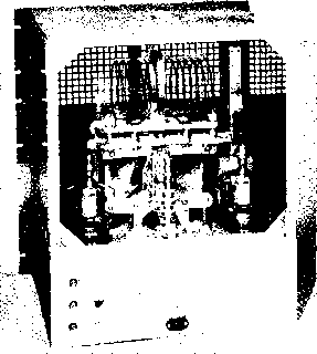 Figure 8 REAR VIEW OF PUSH PULL 4-250A AMPLIFIER The neutralizing rods are mounted on ceramic feedthrough insulators adjacent to each tube socket, low voltage power leads leave the grid circuit compartment via Hypass capacitors located on the lower left corner of the chassis. A screen plate covers the rear of the amplifier during operation. This plate was removed for the photograph. As a summation, three requirements must be met for proper operation of tetrode tubes- whether in a push-pull or parallel mode: 1. Complete isolation must be achieved between the grid and plate circuits. 2. The tubes must be neutralized. 3. The circuit must be parasitic-free. Amplifier The push-pull tetrode ampli- Construction fier should be built around two r-f tight boxes for the grid and plate circuits. A typical layout that has proven very satisfactory is shown in figures 8 and 9. The amplifier is designed around a Barker & Williamson butterfly tuning capacitor. The 4-250A tetrode tubes are mounted at the rear of the chassis on each side of the capacitor. The base shells of the tubes are grounded by spring clips, and short adjustable rods project up beside each tube to act as neutralizing capacitors. The leads to these rods are cross-connected beneath the chassis and the rods provide a small value of capacitance to the plates of the tubes. This neutralization is necessary when the tube is operated with high 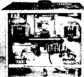 Figure 9 UNDER CHASSIS VIEW OF 4-250A AMPLIFIER The bias supply for the amplifier is mounted at the front of the chassis between the two control shafts. A blower motor is mounted beneath each tube socket. A screened plate is placed on the bottom of the chassis to complete the under-chassis shielding. power gain and high screen voltage. As the operating frequency of the tube is increased, the inductance of the internal screen support lead of the tube becomes an important part of the screen ground return circuit. At some crirical frequency (about 45 JVIc. for the 4-250A tube) the screen lead inductance causes a series resonant condition and the tube is said to be self-neutralized at this frequency. Above this frequency the screen of the tetrode tube cannot be held at ground potential by the usual screen by-pass capacitors. With normal circuitry, the tetrode tube will have a tendency to self-oscillate somewhere in the 120 Mc. to 160 Mc. region. Low capacity tetrodes that can operate efficiently at such a high frequency are capable of generating robust parasitic oscillations in this region while the operator is vainly trying to get them operating at some lower frequency. The solution is to introduce enough loss in the circuit at the frequency of the parasitic so as to render oscillation impossible. This procedure has been followed in this amplifier. During a long series of experiments designed to stabilize large tetrode tubes, it was found that suppression circuits were most effective when inserted in the screen lead of the tetrode. The screen, it seemed, would have r-f potentials measuring into the thousands of volts upon it during a period of parasitic oscillation. By-passing the screen to ground with copper strap connections and multiple by-pass capacitors did little to decrease the amplitude of the oscillation. Excellent parasitic suppression was brought about by strapping the screen leads of the 4-250A socket together (figure 7) and inserting a parasitic choke between the screen terminal of the socket and the screen by-pass capacitor. After this was done, a very minor tendency towards self-oscillation was noted at extremely high plate voltages. A small parasitic choke in each grid lead of the 4-250A tubes eliminated this completely. The neutralizing rods are mounted upon two feedthrough insulators and cross-connected to the 4-250A control grids beneath the chassis. These rods are threaded so that they may be run up and down the insulator bolt for neutralizing adjustment. Because of the compact size of many tetrodes it is necessary to cool the filament seals of the tube with a blast of air. A small blower can be mounted beneath the chassis to project cooling air directly at the socket of the tube as shown in figure 9. Inductive Tuning of Push-Pull Amplifiers The plate tank circuit of the push-pull amplifier must have a low impedance to ground at harmonic frequencies to provide adequate harmonic suppression. The usual split-stator tank capacitor, however, has an uncommonly high impedance in the VHF region wherein the interference-causing harmonics lie. A push-pull vacuum-type capacitor may be used as these units have very low internal inductance, but the cost of such a capacitor is quite high A novel solution to this problem is to era-ploy a split stator capacitor made up of two inexpensive fixed vacuum capacitors. Amplifier adjustment can then best be accomplished by inductive tuning of the plate tank coil as Figure 10 INDUCTIVE TUNING MAY BE EMPLOYED IN HIGH POWER AMPLIFIER Two fixed vacuum capacitors form split-stator capacitance, providing very low inductance ground patfi for plate circuit harmonics. Tuning is accomplished by means ot shorted, single-turn /ink placed in center of tank coil. Shorted link is made from %-inch section cut from copper water pipe. Larger link outside of tank coil is antenna pick-up coil. seen in figure 10. Two fixed vacuum capacitors are mounted vertically upon the chassis and the upper terminals are attached to the plates of the amplifier tubes by means of low impedance straps. Resonance is established by rotation of a shorted copper loop located within the amplifier tank coil. This loop is made of a Ув long section of copper water pipe, two inches in diameter. Approximate resonance is established by varying the spacing between the turns of the copper tubing tank coil. Inductive coupling is used between the tank coil and the antenna circuit in the usual manner. Sufficient range to enable the operator to cover a complete high frequency band may be had with this interesting tuning method. 29-4 Tetrode Pi-Network Amplifiers The most popular amplifier today for both commercial and amateur use is the pi-network configuration shown in figure 11. This circuit is especially suited to tetrode tubes, although triode tubes may be used under certain circumstances. A common form of pi-network amplifier is shown in figure 11 A. The pi circuit forms the matching system between the plate of the amplifier tube and the low impedance, unbalanced antenna circuit. The coil and input capacitor 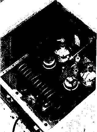 EXCITATION 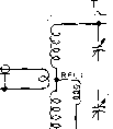 .00 t о о C2 L) L2 о о  T 1 CH 001 -Сб W-nr!5tw-----o?r б 6 BtSCR. B+HV BIAS + о 1 15 V. iTj LOW Z PUT EACITATION RFCI [BJ 100 04-0-  BIAS +  4Mi} RFC2S nnu.r C6 Сз Sa BI-SCR. Bf-HV 0 i 1 1 4 V. NLOW Z /OUTPUT EXCITATION С - :°1 С ИН -001 с 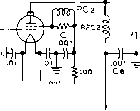 Сг La о 6 B+SCR. B+HV 6 0 - BIAS + 1 15у.Л., LOV Z OUTPUT Figure 11 TYPICAL PI-NETWORK CONFIGURATIONS A-Spiii grid circuit provides out-of-phase voitage for grid neutralization of tetrode tube, ftotary coil is employed in plate circuit, with small, fixed auxiliary coil for 28 Mc. Multiple tuning grid tanii T, covers 3.5 - 30 Mc. without switching. В-Tapped grid and plate inductors are used with bridge type neutralizing circuit for tetrode amplifier stage. Vacuum tuning capacitor is used in input section of pi-networlt. С-Untuned input circuit (resistance loaded) and plate inductor ganged with tuning capacitor comprise simple amplifier configuration. PCi, РСг-57 ohm, 2 watt composition resistor, wound with 3 turns # 18 c. wire. of the pi may be varied to tune the circuit over a 10 to 1 frequency range (usually 3.0-30 Mc.). Operation over the 20 - 30 Mc. range takes place when the variable slider on coil La is adjusted to short this coil out of the circuit. Coil Ll therefore comprises the tank inductance for the highest portion of rhe operating range. This coil has no taps or sliders and is constructed for the highest possible Q at the high frequency end of the range. The adjustable coil (because of the variable tap and physical construction) usually has a lower Q than that of the fixed coil. The degree of loading is controlled by capacitors Cl and Cs. The amount of circuit capacity required at this point is inversely proportional to the operating frequency and to the impedance of the antenna circuit. A loading capacitor range of 100 fifiid. to 2500 jx/xfd. is normally ample to cover the 3-5-30 Mc. range. The pi circuit is usually shunt-fed to remove the d.c. plate voltage from the coils and capacitors. The components are held at ground potential by completing the circuit ground through the choke RFCi. Great stress is placed upon the plate circuit choke RFCs. This component must be specially designed for this mode of operation, having low inter-turn capacity and no spurious internal resonances throughout the operating range of the amplifier. Parasitic suppression is accomplished by means of chokes PC-1 and PC-2 in the screen and grid leads of the tetrode. Suitable values for these chokes are given in the parts list of figure 11. Effective parasitic suppression is dependent to a large degree upon the choice of screen bypass capacitor G. This component must have extremely low induaance throughout the operating range of the amplifier and well up into the VHF parasitic range. The capacitor must have a voltage rating equal to at least twice the screen potential (four times the screen potential for plate modulation). There are practically no capacitors available that will perform this difficult task. One satisfactory solution is to allow the amplifier chassis to form one plate of the screen capacitor. A sandwich is built upon the chassis with a sheet of insulating material of high dielectric constant and a matching metal sheet which forms the screen side of the capacitance. A capacitor of this type has very low internal inductance but is very bulky and takes up valuable space beneath the chassis. One suitable capacitor for this position is the Centralab type 858S-1000, - AMPLIFIER .00* P.A.TUBE 4-250А,етС. CONNECTINS TERMINAL I STRIP LOCATED ON TOP OF EXCITER UNIT. .RFC - BIAS Figure 12 CAPACITIVE COUPLING CIRCUIT BETWEEN EXCITER AND FINAL AMPLIFIER STAGE MAKES USE OF ONE COMMON TANK CIRCUIT Grid circuit ot amplifier stage serves as plate circuit of exciter in this simplified circuit. Leads between the tubes must be kept short and direct. rated at 1000 fifiid. at 5000 volts. This compact ceramic capacitor has relatively low internal inductance and may be mounted to the chassis by a 6-32 bolt. It is shown in various amphfiers described in this chapter. Further screen isolation may be provided by a shielded power lead, isolated from the screen by a .001 fiid. ceramic capacitor and a 100 ohm carbon resistor. Various forms of the basic pi-network amplifier are shown in figure 11. The A configuration employs the so-called all-band grid tank circuit and a rotary pi-network coil in the plate circuit. The В circuit uses coil switching in the grid circuit, bridge neutralization, and a tapped pi-network coil with a vacuum tuning capacitor. Figure IIC shows an interesting circuit that Is becoming more popular for class ABl linear operation. A tetrode tube operating under class ABl conditions draws no grid current and requires no grid driving power. Only r-f voltage is required for proper operation. It is possible therefore to dispense with the usual tuned grid circuit and neutralizing capacitor and in their place employ a simple load resistor in the grid circuit across which the required excitation vohage may be developed- This resistor can be of the order of 50 - 300 ohms, depending upon circuit requirements. Considerable power must be dissipated in the resistor to develop sufficient grid swing, but driving power is often cheaper to obtain than the cost of the usual grid circuit components. In addition, the low impedance grid return removes the tendency towards instability that is so common to the circuits of figure llA and IIB. Neutralization is not required of the circuit of figure UC, and in many cases parasitic suppression may be omitted. The price that must be paid is the Figure 13 MIDGET LINEAR AMPLIFIER FOR MOBILE SIDEBAND OPERATION FEATURES WATER COOLED 4W-300B TETRODE TUBES Miniature amplifier is comparable in size with sideband exciter. Antenna, plate, and screen current are monitored by panel lamps used in place of larger and more expensive meters. Inductor slug of grid coil is located below plate circuit tuning capacitor. additional excitation that is required to develop operating voltage across grid resistor Ei. The pi-network circuit of figure IIC is interesting in that the rotary coil L: and the plate tuning capacitor G are ganged together by a gear train, enabling the circuit to be tuned to resonance with one panel control instead of the two required by the circuit of figure llA. Careful design of the rotary inductor will permit the elimination of the auxiliary high frequency coil Li, reducing the cost and complexity of the circuit. A single tuned circuit may be employed to couple the power amplifier grid circuit to the buffer stage as shown in figure 12. Care must be taken to ensure that a good ground exists between the two circuits. 29-5 A Compact Linear Amplifier for Mobile SSB Single sideband transmission is ideal for mobile operation because it provides the maximum amount of talk power for a given amount of primary power drain. The new three phase alternator systems available for automotive use are capable of supplying over one rhousand watts of primary power, making the proposition of a kilowatt sideband transmitter a reality. The compaa kilowatt linear amplifier described in this section is designed for remote control operation on any one amateur band. It may be driven by any exciter capable of one or two watts p.e.p. output. Amplifier The circuit of the mobile linear Circuit amplifier is shown in figure 14. Designed around two Eimac 4W-300B water cooled tetrode tubes, the amplifier may nevertheless be used with 4X-250B or 4CX-300A tubes if air cooling is employed. For purely mobile operation the water cooled tubes are recommended as air blowers are bulky, noisy, and draw a high current from the automobile primary power system. Water cooling, although unfamiliar to many amateurs, is relatively simple and inexpensive. A Stewart-Warner fuel pump is used to pump distilled water from a reservoir through polyethylene tubes to the anodes of the 4W-300B tetrode and back through other tubes to the reservoir. This container is a surplus one gallon G.I. gasoline can (figure 17). The temperature of the water remains under 100°F. even when the transmirter is operated for extended periods of time. The water jackets of the tubes are connected in series as shown in the drawing. It has been found by experiment that it is not necessary to have any other form of cooling medium to maintain the tubes at a safe temperature. The water pump draws a current of 0.2 amperes at maximum pumping speed. It is mounted in a corner of the turtle-back of the automobile, along with the G.I. water can. The pump motor is connected so that it starts as soon as filament voltage is applied to the two 4W-300B tubes. The two tetrode tubes are connected in parallel with a parallel resonant plate circuit and a simple pi-type grid circuit. The plate circuit consists of a minature Jennings GSLA-120 variable vacuum capacitor (Ci) in parallel with a silver plated copper tubing tank coil. Plate voltage is fed to the tubes through a r-f choke and the anodes of the tubes are coupled to the tank circuit through a 500 i/ifd., 5 KV ceramic capacitor. The low impedance antenna system is directly tapped at a low impedance point on the tank coil. A small б volt automobile headlamp is placed in series with the antenna lead to provide a simple indicaror of r-f current. Antenna transfer is accomplished by means of a minature Jennings RB-1 s.p.d.t. vacuum relay. Special low impedance sockets for these tubes are supplied by the Eimac Co. and their use is recommended. The sockets have a built- 1 ... 58 59 60 61 62 63 64 ... 80 |
|
© 2026 AutoElektrix.ru
Частичное копирование материалов разрешено при условии активной ссылки |