 |
 |
 |
| Главная Журналы Популярное Audi - почему их так назвали? Как появилась марка Bmw? Откуда появился Lexus? Достижения и устремления Mercedes-Benz Первые модели Chevrolet Электромобиль Nissan Leaf |
Главная » Журналы » Simple coaxial reflectometer 1 ... 59 60 61 62 63 64 65 ... 80 4W-300B/ 4X-250B EXCITERi- J3 TO RECEIVER  GND. -BIAS B- FIL. +SCR. RELAY CONTROL Figure 14 SCHEMATIC, MOBILE LINEAR AMPLIFIER Ci-120 niifd., SKV variable vacuum capacitor. Jennings GSLA-120 Ll-(20 meters;.- 15 turns # Гве., Yg diam., 1 long. Adjust to resononce with Ji shorted and tubes in sockets. Lz-f20 meters; 6 turns, Yt-inch silver plated copper tubing, IVi i-d., 2 long. Adjust antenna tap for proper loading, HFC-2.5 mh. National R-100 HFCj-225 turns #28 manganin, Vb dia., 2 long, in series with National H-IOO choice. Or, heovy-duty Ray par RL-102 choke may be substituted for these two items. RYi-SPOT relay, d.c. coil to match battery voltage. Jennings RB-1 vacuum relay employed Bi, Вг, Вз-Indicotor pilot lamps. Bi should have 500 mo. rating; Вг, 60 ma, rating; and Вз may be automobile headlight lamp heavy enough to carry antenna current. in screen capacitor which provides an extremely low impedance screen ground return circuit, reducing the problem of parasitics to a minimum. A simple series tuned input circuit is employed in the grid circuit. The internal input capacitance of the tubes is effectively in parallel with the grid coil resonating it to the operating frequency. Since no grid current is drawn during class ABl operation a small battery may be used to provide the correct value of operating bias. Flashlight bulbs are placed in the screen and negative high voltage leads instead of meters to conserve space. Figure 15 SMALL SIZE OF LINEAR AMPLIFIER IS DUE TO USE OF MINIATURE 300 WATT, WATER COOLED TETRODE TUBES Parallel operation of the 4W-300B tubes is employed. Piate tank inductor is at right, with miniature variable vacuum capacitor behind it. Plate choke is in the foreground, made up of a 2.5 mh. choke in series with a home-made unit. Commercial choke may be used, as indicated in patis list of figure 14. Special low inductance fimae sockets are employed with the tubes. Vocuum-type antenna relay is at top, center. Amplifier Class ABl operation plus the Construction complete absence of parasitics results in a very minimum amount of harmonic generation. The use of a low inductance variable vacuum capacitor provides an effective return path to ground for high frequency harmonics appearing in the  pjate circuit of tlie ajnplifier. As a result, a very minimum of shielding and lead filtering Is required with this amplifier even when 28 Mc. operation is desired. Placing the amplifier within the turtle-back of the automobile and the insertion of a low pass TV-filter in the coaxial antenna line reduces TVI-producing harmonics to such a low value that no interference is caused to a nearby television receiver tuned to a channel 2 signal of moderate strength. The amplifier is built upon a shallow metal deck just large enough to hold the various components (figure 15). The two 4W-300B tube sockets are placed in the left area of the chassis with the variable vacuum capacitor mounted at the right corner of the front panel. The silver plated copper tubing tank coil is bolted between the rear terminal of the capacitor and one of the capacitor mounting bolts. Make sure that a good connection exists between the capacitor, the panel, and the chassis as this ground return is part of the plate tank circuit. Centered on the front panel are the three pilot lamp indicator sockets, the antenna changeover relay and the coaxial antenna receptacles. At the rear of the chassis is the plate r-f choke. Two r-f chokes in series were used in the original model, but have since been replaced with one of the new Raypar miniature chokes (see parts list, figure 14). The grid circuit components are mounted in the under-chassis area of the amplifier (figure 16). A shield plate is placed over the bottom of the amplifier to completely isolate the components from the field of the plate tank circuit. Grid coil Li is mounted to the panel and slug-tuned to resonance. The grid terminals of the tube sockets are connected with a short length of 34-inch wide copper Strap. A wire interconnecting lead will invari-bly lead to VHF parasitic oscillation of the stage. Amplifier The amplifier must be completely Operation tested before it is installed in the automobile. Grid, plate, and screen meters should be inserted in the power leads to the amplifier and preliminary tune-up into a dummy load is done at reduced screen and plate potentials. A small driving signal is applied to the amplifier and grid coil Li resonated. The screen and plate currents will increase sharply in value when the grid circuit is tuned to the operating frequency. The degree of plate loading is determined by the position of the antenna tap on the plate tank coil. Screen current is a very sensitive indicator of the degree of amplifier antenna loading. At plate potentials of 2000 or so the total screen current at one kilowatt peak input is about 10 milliamperes, varying slightly with individual tubes. As the plate potential is raised above this value the screen current gradually drops until at 3000 volts plate potential the screen current is near zero. In general, overcoupling of the amplifier will be indicated by low screen current and undercoupling will result in high values of screen current. At 3000 volts plate potential, an overcoupled condition is indicated by negative screen current, and undercoupling will produce positive screen current. Only a slight deviation from zero current during voice operation indicates proper operation. Maximum peak input under these conditions is about 1500 watts (3000 volts at 500 ma.). The Power Supply This amplifier is designed to work from a three-phase alternator system of 1500 watts capacity. A three-phase rectifier supply is employed to  Figure 16 UNDER-CHASSIS VIEW OF MOBILE SSB LINEAR AMPLIFIER SHOWS SIMPLICITY OF CIRCUIT Input circuit is at the left, with grid terminals of socket connected with short copper strap. Screen series resistors are at center, with grid choke and power f>lug at right. Under-chassis area is enclosed with aluminum bottom plate held In place with self-tapping sheet metal screws. provide 2500 volts at 400 milliamperes (figure 18). Since the frequency of the ahernator is 120 cycles or higher and the ripple output of the supply is less than 5% before filtering, a small capacitor is sufficient to produce pure d.c. and to provide good regulation for peak power surges. In the interest of power conservation and compactness the new Sarkes-Tarzian silicon rectifiers are used in the high and low voltage power supplies. These rectifiers can be operated in series with no special selection. It is possible therefore to provide compact and inexpensive high voltage rectifiers by connecting a number of the standard type Л1-.500 rectifiers in series to obtain the required peak inverse voltage rating. The higher cost of the bank of silicon rectifiers as compared to vacuum tube rectifiers is offset by the elimination of the tubes and a special three-phase filament transformer. If desired, the special Sarkes-Tarzian 280-SM rectifier stack may be substituted for the individual units. Since the 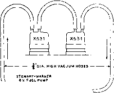 
ev. D.c. o. г A {turns on with >t-S3l fils) Figure 17 WATER CIRCULATION SYSTEM FOR X-531 (4W-300B} TUBES alternator will not supply much more than 1500 watts, the primary voltage drops rapidly Tl {SEC. it I ) Tl (Pf>l.) 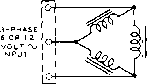 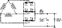 0-t-S25V. (SCREEN) AT 100 MA Tl (.sec. #2 ) 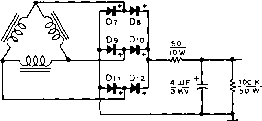 0-t-250ov. (plate) AT aoo MA. Figure 18 SCHEMATIC, THREE-PHASE MOBILE POWER SUPPLY D;-De-500 mo. silicon rectifier. Sorfces-Torzion M-500 D--Dj2-2.5 KV, 130 ma. rectifier stock. Sorkes-Torzian 280-SM silicon rectifier. See text for substitute Ti-Speciol three-phose power tronsformer to deliver 2500 volts d.c. at 400 mo., and 325 volts d.c. at IOO mo. Design data and core may be obtained from Arnold Engineering Co., Marengo, III. Core number: ATA-1S73 with 12-mil Hypersil laminations for 120 cvc/e operation. Primary winding: (12 volts)-focb leg, 15 turns #8e. wire ( 6 voltsj-Eoch ieg, 7 turns #5e. wire Low Voltage secondary. Each leg, 265 turns #30e. wire High Voltoge secondary: fach leg, 2400 turns #28e. wire 7.5 KY insulation employed. High voltage winding placed next to core, low voltage secondary next, and primary winding outside, with 2KY insulation. Vacuum impregnate windings. When finished, polarize windings by placing 6 volt, 50 c.p. lamps in series with each primary lead. Bulbs should only glow red when primary windings are correctly polarized. Correct polarization of secondary windinas will deliver desired output voliaaes.  under overload conditions and the silicon rectifiers cannot be damaged, even with a direct short circuit across the output terminals of the high voltage power supply. This unusual equipment is described for others who may wish to make models based upon ideas presented in the design. Although some of the components shown in the amplifier or power package are unique or are not readily available, it is hoped that the reader can make use of his facilities and abilities to use many of the ideas shown herewith. Variations Upon the Basic Circuit It is possible to increase the power level of this amplifier by merely adding more tubes connected in parallel with the original two. Three tubes will permit a p.e.p. of two kilowatts at 3000 volts plate potential. ю t) *  Figure 20 MULTI-BAND LINEAR AMPLIFIER FOR MOBILE SERVICE FEATURES THREE SEPARATE TANK CIRCUITS SWITCHED BY CONTROL RELAYS Three vacuum tank capacitors are located at top left corner of panel. To the right is thermocouple r.f. ammeter in output circuit. Zero-center screen meter and 0-SOQ d.c. ma. plate meter are at lower right. Figure 19 WATER COOLED LINEAR AMPLIFIER PACKAGED FOR FIXED STATION USE Either 4W-300B (water cooled) tubes or 4X-2S0B (air cooled) tubes may be employed in this compact linear amplifier. Input and output capacitors of pi-network are vacuum units, and power supply (three phase) is contained within the cabinet (right). Wide band plate r.f. choke is at left of cabinet, running from front io back. Amplifier operates at plate potential of 3000 volts, with p.e.p, of 1500 watts. Four tubes in parallel will provide a p.e.p. of two kilowatts at 2000 volts plate potential. An experimental amplifier having five tubes in parallel has run 3500 watts p.e.p. into dummy loads. The five tube amplifier employed neutralization and parasitic suppression and performed in normal fashion with no signs of instability. Shown in figure 19 is a fixed station version of this amplifier. Employing a pi-section plate tank circuit and a three-phase power supply, the complete unit is built within a standard 12 X 16 X 19 cabinet. Of unusual interest is the r-f choke employed in the plate circuit of the linear amplifier stage. This choke is usually a critical item as the full value of r-f plate potential is developed across it. For maximum amplifier efficiency and minimum loss the plate choke must present an impedance of several thousand ohms at any frequency of operation. Special r-f chokes are available that will perform this exacting task, and the one described equals the best of the commercial items at a fraction of the cost. The choke coil consists of 250 turns of #22 double cotton covered manganin wire close-wound upon a Vl-iach diameter wooden dowel rod. The small d.c. resistance of the winding effeaively destroys undesired resonance effects within the choke, providing a high and uniform impedance across all amateur bands from 80- to 10-meters. The choke will work well up to power levels of the order of 2000 watts, p.e.p., or 1000 watts, plate modulated. 29-6 A Mulfi-band Mobile Lineor Amplifier The kilowatt linear amplifier described in this section is designed for remote control mobile operation on any three amateur bands. The unit shown in the photographs operates on the 80, 40, and 20 meter bands, but operation on 15 or 10 meters is possible by altering the constants of the plate tank circuit. 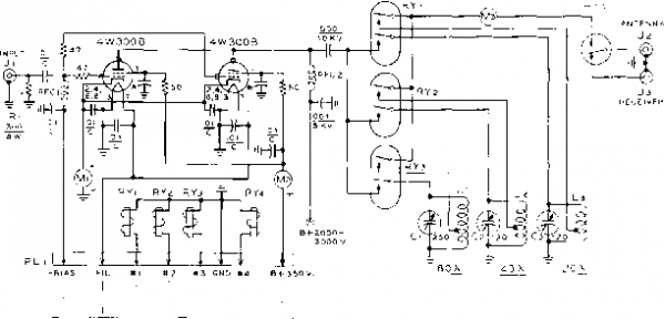 note *<r = screen bi-pass in tube socket 60V Bi ON* -- dSl BAND PUSH-TO TO FIL.f SWITCH -TALK POWER CIRCUIT SUPPLY Figure 21 SCHEMATIC, MULTI-BAND MOBILE LINEAR AMPLIFIER Ci, Cj, Сз-Jennings variable vacuum capacitor, type GSLA. Use 250 fiiifd. unit for 80 meters and 720 /ilifd. units for other bands. Adjust coils to resonate circuit with capacitors set near maximum value. Ll-76 turns, Y4-inch silver plated copper tubing, 2/i i.d., 3/j long. Antenna tap approximately 2 turns from ground end. Li-8 turns, same as Li. Antenna tap approximately 2 turns trom ground end. Ls-5/2 turns, same as Li. Antenna tap approximately З/4 turn from ground end. RFC-2.5 mh. National R-100 RFCl-Wide band choke, 500 ma. rating. Ray par RL-102 RY i, 3-DPOr relay, d.c. coil to match battery voffoge. Jennings type RB vacuum relay RYj-SPSr relay, d.c. coil to match battery voltage. Jennings type RB-1 vacuum relay (Jennings Radio Co., San Jose, Calif.) Ml-0 - 500 mo. d.c. meter Ml-500 - 0 - 500 d.c. micro-ammeter, zero center movement, shunted to 50 - 0 - SO ma. Мз-0 - 5 ampere, r.f. ammeter Amplifier The amplifier employs two ex-Circuit ternal anode tetrodes such as the 4W-300B, 4X-250B, or 4CX-300A. The water cooled tubes are recommended for mobile operation, while the air cooled tubes may be used for fixed operation. The schematic of the amplifier is shown in figure 21 and is a version of the untuned input circuit of figure lie. Three separate parallel tuned plate circuits are employed in the linear amplifier. Each circuit is made up of a silver plated copper tubing coil paralleled with a miniature variable vacuum tuning capacitor. These new Jennings capacitors are extremely small in size and are tuned by means of a slotted shaft instead of the more cumbersome and expensive counter dial arrangement. The low impedance mobile antenna system is tapped directly 10 experimentally determined points on the tank coils. The proper tuned circuit is switched to the linear amplifier by means of miniature vacuum-sealed d.p.d.t. relays. Three relays are required, one for each tank circuit. The tank circuits are relatively low impedance devices as they are tuned with capacitors having a large value of maximum capacitance, permitting good efficiency in matching the tubes to the very low load impedance presented by the mobile antenna system. Although the tubes operate with zero driving power the resistive input system demands that approximately 9 watts of excitation be employed to develop 50 volts (peak) across the 300 ohm circuit impedance. The mobile SSB exciters ot Chapter 28 used in conjunction with a 2E26 linear buffer stage will supply an abundance of excitation for this kilowatt amplifier. Alternatively, a high impedance grid circuit such as shown in figure IIB may be used, dropping tbe grid driving power level to a watt or so. Selection of the proper tank circuit is accomplished by means of a rotary switch (S2) located at the drivers position in the automobile. One of the three miniature plate circuit relays at a time may be operated by this switch. The antenna change-over relay is actuated by the push-to-talk circuit in the microphone. Amplifier The amplifier is built upon Construction a shallow metal deck (figure 22). The two Eimac low inductance sockets for the tetrode tubes are placed in the rear corner of the chassis with the 80 meter tank coil to their left. One end of the coil is bolted to the chassis and the other end is attached to the rear terminal of the variable vacuum capacitor which is mounted to the metal panel. The 40 and 20 meter tank coils are mounted directly to their respective tuning capacitors. The front area of the chassis is taken up with the plate circuit switching relays RYi-2-а. These relays are bolted to the chassis and connections are made to the various terminals by means of flexible 14-inch silver plated copper strap. The three meters are mounted in the remaining panel space. Under-chassis wiring is extremely simple, as seen in figure 23- The socket grid terminals are connected together with a short length of copper strap. A shield is not required over the bottom of the chassis since the grid circuit is untuned. Amplifier The amplifier should be bench-Operation tested before it is placed within the automobile. Operaring conditions are similar to those described in Section 29-5. A center-reading milliammeter is used in the screen circuit to observe screen current during loading adjustments. Linear operation may be checked with the aid of envelope detectors, as discussed in an earlier chapter. Normal operation takes place at 2500 volts at 400 milliamperes, peak current. Screen current is less than 5 milliamperes under these conditions. Grid current is zero. 29-7 An Inexpensive Cat-hode Driven Kilowat-f Amplifier An objectionable feature of triode tubes is that they must be neutralized in conventional grid driven circuits. Tetrode tubes may often dispense with the neutralizing circuit, but they require a screen power supply whose cost and complexity dissipate the saving afforded by the elimination of the neutralizing circuit. The use of a cathode driven amplifier employing zero bias tubes overcomes these two disadvantages. The grids act as an excellent screen between the plate and cathode so neutralization is not usually required. The very small plate to cathode capacitance permits a minimum of intercoupling on frequencies below 30 Mc. when inexpensive tetrode or pentode tubes are used. No screen or bias supplies are required. 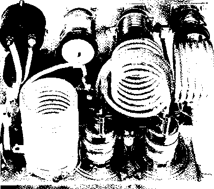 Figure 22 REAR VIEW OF MULTI-BAND MOBILE LINEAR AMPLIFIER The three amplifier tartk coils are connected between the variable vacuum capacitors and chassis ground. Plate voltage is shunt-fed to the linear amplifier tubes (4W-300Bs or 4X-2S0Bs). Antenna relay is at left. Extremely low harmonic content of class AB 1 amplifier operation requires no TVI screening or other enclosure to prevent radiation of undesired harmonics. Feedthrough A large portion of the exciting Power power appears in the plate circuit of the cathode driven stage and is termed the feedthrough power. In any amplifier of this type, whether it be triode or tetrode, it is desirable to have a fairly large ratio of feedthrough power to peak grid driving power. The feedthrough power acts as a swamping resistor across the driving circuit to reduce the effect of grid loading. The ratio of feedthrough power to driving power should be at least 10 to 1 for best stage linearity. Class ABI Cathode Driven Amplifiers The only way that the advantages can be taken of the inherent feedback in a cathode driven amplifier is to drive it with a source having a high internal impedance and to operate the stage class ABl without grid or screen current. It is a characteristic of class ABl cathode driven (so-called grounded grid ) amplifiers that a variation in load impedance on the stage reflects back as a nearly proporrional change at the input because the input and output circuits are essentially in series. In the same manner, a change in gain (such as may be caused by a nonlinearity of gain with respect to signal level) of a cathode driven stage reflects back as a change in the input impedance of rhat stage. If the cathode driven stage is fed by a source having high internal impedance such as a tetrode amplifier, changes in gain or non-linearity in the cathode driven stage will be compensated for. For example, if the gain of the cathode driven stage drops slightly, the input impedance of the stage will increase and the load impedance on the driver stage will rise. If the driver has high internal Impedance the output voltage will also rise when its load impedance rises. The increased output voltage will raise the output voltage of the cathode driven stage so that the output is nearly up to where it should be even though the gain of the cathode driven stage is low. The equivalent circuit for this action is shown in figure 24, True class ABl cathode driven amplifiers, however, have rather low stage gain and the use of low-mu triodes is required for reasonable efficiency. Such low gain circuits require more stages to reach a given power level. High driving voltage is required which is difficult to achieve in the cathode circuit. Since Il s.ems impractical to operate most available tubes class ABl in a cathode driven circuit (i.e., no grid current and no screen current) the possibility of taking advantage of the inherent feedback in the circuit is lost because a low driver 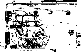 Figure 23 UNDER-CHASSIS VIEW OF MULTI-BAND LINEAR AMPLIFIER Coaxial input receptacle is ot left, with com-posit/on-type grid resistors. Simplicity of circuit requirei relatively few components beneath fhe chassis. Grid terminals of sockets are connected with wide copper strap. source impedance is then required to supply grid driving power for class AB2 operation. The latter class of operation offers stage gain figures of 10 to 25 with moderate values of cathode excitation voltage. The linearity, however, is approximately the same as for conventional grid driven circuits having low source impedance, and about 30 decibels signal-to-distortion ratio is the maximum that can be achieved. 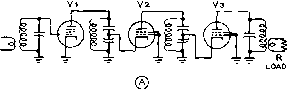 -(y-ЛУ- V2R2 I -(V)-W-j-(Vh VaRa -nW- load R Figure 24 EQUIVALENT CIRCUIT OF CASCADE CLASS ABI CATHODE DRIVEN AMPLIFIERS A-Cathode driven amplifiers may be arranged in cascade to provide high output levels. Any variation in load impedance (R) reflects back as nearly proportional change at the input, as input and output circuits are essentially in series as shown in figure S. В-fquivolent circuit of figure A. Ri has a very high resistance, and Ri and Rj have very low resistances compared to the load R.  Figure 25 CATHODE DRIVEN KILOWATT AMPLIFIER FOR 40 AND 80 METERS Cathode driyen amplifier presents ultimate in simplicity and stability. Designed around two 803 tetrodes, this kilowatt amplifier for 40 and 80 meter operation has only plate tank tuning control and plate current meter on panel. Amplifier is completely enclosed for reduction of spurious radiation. A Practicol Cothode Driven Amplifier Shown in figures 25, 27, and 28 is a cathode driven amplifier designed for 40 and 80 meter operarion. It is capable of 1000 watts power input and may be employed for SSB, c.w., or a.m. phone. Combined grid driving and feedthrough power is approximately 110 watts for 1 kilowatt input. Actual grid driving power is of the order of 9 to 10 watts, so the ratio of feedthrough to drive power is about 10 to 1. The schematic of the amplifier is shown in figure 26. Two 803 tetrode tubes are used in parallel in cathode driven configuration. These tubes are available on the surplus market for a dollar or so and perform very well up to approximately 10 Mc. All three grids of the tubes are returned to ground and the tubes operate in near zero bias condition. The internal screening of the tubes begins to deteriorate in the 15 Mc. region and amplifier instability may be encountered above 10 Mc. unless precautions are taken to ensure that the grids remain close to r-f ground potential. When operating in rhe 3.5 - 7 Mc. region it is entirely possible to apply the r-f driving voltage directly to the filament circuit without the necessity of adding filament r-f chokes to isolate the driving voltage from the filament transformer. This makes for circuit simplicity and lower initial cost. If this circuit is used with high frequency tubes such as the 813 and 7094, the use of filament chokes for operation above 7 Mc. is recommended. This type of amplifier has a tendency toward parasitic oscillations in the 100 Mc. region at which point the inherent inductance of the ground paths begins to affect operation. Variations in grounding technique can eliminate the parasitic, but the addition of parasitic suppressors in the plate leads of the tubes makes the circuit relatively insensitive to variations in the ground return path. Amplifier The amplifier is built upon a Construction 10 X 19 X 4 aluminum chassis. The plate tuning capacitor Cl is centered on the chassis with the two 803 tubes mounted to one side. The tube sockets are recessed below the chassis to bring the top of the tube base level with the гор of the chassis. The plate r-f choke and bypass capacitors are mounted between the rubes. On the opposite side of the tank capacitor is the tank coil and rhe r-f thermocouple (figure 27). In the under-chassis area the only components are the cathode current meter, the filament transformer, and the small parts associated wirh the filament circuit. Pins 2, 3, and 4 of each socket are grounded to the metal rods 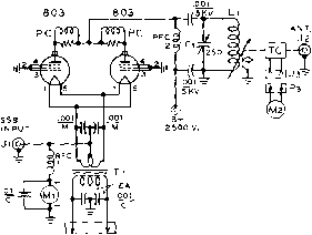 Figure 26 SCHEMATIC, CATHODE DRIVEN AMPLIFIER Cl-250 nufd., SOOO Yolt spacing Ll-40 or 80 meter inductor. Cut to resonate to frequency with Ci near full capacity. Antenna coil S turns. PC-40 ohm, 2 watt composition resistor wound with 6 turns # 78 e. wire TC-R.f. thermocouple, OS amperes T,-JO YOlis at 70 amperes, Stancor P-6461 RFC-1.0 mh. Johnson 102-752 RFCi-Heavy duty plate choke. National R- 17 5 A M,-0-500 d.c. milliamperes Ml-0-5 amperes, r.f. (Used with TC) Figure 27 REAR VIEW, CATHODE DRIVEN 803 AMPLIFIER Plote tuning copocitor is ot tiie center, witii tank coil to left. The 803 tubes (right) are mounted with sockets below deck, so that tops of bases are level with chassis. Piate r.f. choke is placed between tubes, with poro-sitic choices (PC) supported from top termi nal of choke. supporting the sockets. The complete amplifier is enclosed in a shield made of aluminum. Holes are drilled above the 803 tubes in the top sheet (figure 25) and in the rear plate to permit circulation of air about the tubes. Amplifier The resting plate current of the Operation amphfier under quiescent condition is between 30 ma. and 75 ma. depending upon the plate voltage, climbing to 450 ma. or so under full excitation at a plate potential of 2500 volts. Care should be taken in tune-up and full excitation should never be applied unless the amplifier is operating at rated plate voltage with maximum antenna loading. Applying full drive to the tubes with no plate voltage will surely cause damage to the grid structure of the tubes. The meter indicates plate and screen current; actual plate current is about 40 milliamperes lower than the meter reading. At 1000 watts p.e.p., the power output measures approximately 600 watts. Tuning of the plate circuit is facilitated by means of a thermocouple r-f meter placed in the coaxial lead to the antenna coaxial receptacle. 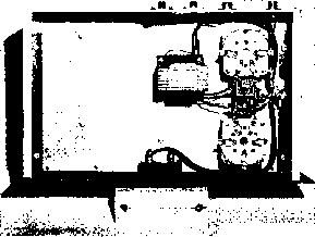 Figure 28 UNDER-CHASSIS VIEW OF CATHODE DRIVEN AMPLIFIER input cooxiol connector is at the right on rear of chassis. Mica filament bypass capacitors are placed between the tube sockets, with RFCl beneath them. 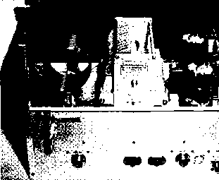 29-8 A Low Distortion Sideband Linear Amplifier A properly designed grounded grid linear amplifier is a very satisfactory high level stage for a sideband transmitter, even though the possibility of taking advantage of the inherent feedback is lost because of the reasons explained in Section 29-7 of rhis chapter. With care, a signal-ro-distortion ratio of 30 decibels can easily be achieved and the circuit is unsurpassed for stability and ease of operation. Data given in the tube manuals and instruc-rion sheets are usually derived for maximum tube output rather than the condition of minimum distortion. It is therefore necessary to adjust circuit operating voltages to arrive at a satisfactory power output level consistent with a pre-set value of maximum allowable distortion. The maximum distortion level for this amplifier was set at 30 db S/D. At this figure 350 watts output p.e.p. can be obtained at 3000 volts plate potential, and 680 watts output p.e.p. can be obtained at 3500 volts. The Grounded For maximum shielding with-Screen in the tube, it is necessary to Configuration operate both grid and screen at r-f ground potential. At the same time, the control grid has a negative operating bias appHed to it, and the screen has a positive operating potential. Both elements of the tube, therefore, must be bypassed to ground over a frequency range that includes the operating spectrum and the region of possible VHF parasitic oscillations. This is quite a large order. The inherent inductance of the usual bypass capacitors is sufficient to introduce sufficient regeneration into the circuit to degrade the linearity of the amplifier at high signal levels even though the instability is not great enough to cause parasitic oscillation. The 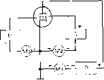
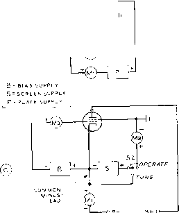 Figure 29 GROUNDED SCREEN GRID CONFIGURATION PROVIDES HIGH ORDER OF ISOLATION IN TETRODE AMPLIFIER STAGE A-Typical amplifier circuit has cathode return at ground potential. All circuits return to cathode. В-All circuits return to cathode, but ground point has been shifted to screen terminal of tube. Operation of the circuit remains the same, as potential differences between e/ements of the tube are the same as in circuit A. С-Practical grounded screen circuit. Common minus lead returns to negative of plate supply, which cannot be grounded. Switch Si removes screen voltage for tune-up purposes. solution to this problem is to eliminate the screen bypass capacitors by actually grounding the screen terminals of rhe amplifier to the chassis by means of a low inductance strap. It is possible to do this by juggling the ground return of the amplifier, as shown in figure 29. Circuit A shows the conventional d.c. return paths wherein all power supplies are returned to the grounded cathode of the stage. Meters are placed in the common return leads, and each meter reads only the current flowing in the singular circuit. The d.c. ground lead is removed from the cathode in circuit В and placed at the screen terminal of the tube, Circuit operation is still the same, as all power supply returns are still made to the cathode of the tube. The only change is that the screen r.f. ground and d.c. ground are now one and the same. The cathode circuit is now at a negative potential with respect to the chassis ground by an amount equal to the screen voltage. In addition, the return of the high voltage plate supply is now negative with respect to ground by an amount equal to the screen voltage supply. A practical version of this circuit is shown in figure 29C. The grid bias and screen supplies are incorporated in the amplifier and separate terminals are provided for tbe positive and negative leads of the high voltage supply. A tune-operate switch is added to the circuit which removes the screen potential for tune-up purposes. The negative of the high voltage supply floats below ground at the value of the screen voltage. This circuit is unique in that it requires a mental orientation of the user to accept the fact that d.c. ground is no longer ground. However, the circuit is no more complex than the usual grounded cathode d.c. return circuit, and the advantage of having the screen at r.f. ground potential far outweighs the unusual aspects of the circuit. Operation of the circuit is normal in all respects, and it may be applied to any form of tetrode amplifier with good results. The Amplifier The circuit of an operation-Circuit al cathode driven, grounded screen amplifier is shown in figure 30. A 4-250A or 4-400A tetrode tube is used with an untuned cathode circuit and a pi-network plate circuit. Bias and screen supplies are included in the amplifier. The important operating parameters are also showm in the diagram. P.e.p. excitation is 12 watts (including losses) for 3000 volt operation and about 22 watts (including losses) for 3500 vok operation. The resonant plate circuit is capacitively coupled to the amplifier tube and consists of a 300 /x/ifd. variable vacuum capacitor, a kilowatt tapped-coil turret, and a 1500 fd. variable air-type loading capacitor. D.c, ground is established by returning the output section of the network to ground by means of choke RFC-3. Three .001 /xfd., 5 KV ceramic capacitors in parallel form the plate blocking capacitor. The high voltage is applied to the tube via a Raypar heavy duty r.f. choke in series with two air wound VHF choke coils. Escape 1 ... 59 60 61 62 63 64 65 ... 80 |
||||||||||||||||||||||||
|
© 2026 AutoElektrix.ru
Частичное копирование материалов разрешено при условии активной ссылки |