 |
 |
 |
| Главная Журналы Популярное Audi - почему их так назвали? Как появилась марка Bmw? Откуда появился Lexus? Достижения и устремления Mercedes-Benz Первые модели Chevrolet Электромобиль Nissan Leaf |
Главная » Журналы » Simple coaxial reflectometer 1 ... 60 61 62 63 64 65 66 ... 80 4-400A INPUT J \ COMMON MINUS-LEAD CH \  RFC2§ SKV о L 001 SKV ® r i ВРсг; л SCREEN ADJ. ($) @ - s JeJio COM- GNOMON 0,1 c4c ILUWtH ea, C = o.iajF- СтРСь^Сб RELAY 115V. CONTROL HH .001 @ SKV B+3000-3500 V. NOTES; \. ALL R£SISTORS 1 WATT UNLESS OTHERWISE SPECIFIED CLASS ABl OPERATING CONDITIONS, 4- 250A / 4-400A
Figure 30 SCHEMATIC, LOW DISTORTION LINEAR AMPLIFIER Cj-300 iififd., lOKV variable vacuum capacitor. Jennings UCS-300 Сг-1500 iiiiid., variable capacitor. Cardwell 8013 Cj-IOO niifd. variable ceramic Ci-Cr-O.I fifd., 600 volt bulktiead-type capacitor. Sprague Hypass L,-S,-Barker & Williamson #850 pi-network inductor, /nductances: 80 meters, 13.5 /ih.; 40 meters, 6.5 цН.; 20 meters, I.7S iMti.; 15 meters, I дй.; 10 meters, 0.8 tifi. Lj-Dual winding filament choke. B&W FC-IS, IS amperes capacity Tl-5 volts ot 10.5 amperes. Stancor P-6I35 Г,-335 - 0 - 335 volts, 75 ma. Chicago PSC-70 CHi-8 henry, 85 ma. Stancor C-1709 Di-Di-500 ma. silicon rectifier. Sarkes-Tarzian M-SOO Di-Diode, type IN67 or equivalent M,-0 - 800 ma. d.c, meter. Marion type MM3 Ml-0 - 50 ma. d.c. meter. Marion type MM3 Mj-0 - 50 ma. d.c. meter. Marion type MM3 RFC:-Heavy duty wide band r.f. choke, 800 ma. Ray par RL-lOO RFCj-20 turns #20e, oirwound, 1/2 diam, I long RFC,-2.5 mh. National R-IOO 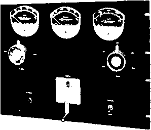 of r.f. energy through rhis lead is thus held to an absolute minimum value. Driving power is coupled to the filament circuit of the tube through two .001 /xfd. ceramic capacitors. The filament transformer is isolated from the exciting voltage by means of a bifilar wound r.f. choke coil, capable of carrying the filament current of the tube (10.5 amperes). A dual purpose power supply delivering 375 volts serves as screen and bias source. The output voltage of the supply is held constant by three regulator tubes in series. The common minus lead (see figures 29 and 30) is at the juncture of the regulated -75 volts and the regulated 300 volts. The supply thus delivers -75 voits for the bias circuir and plus 300 volts for the screen circuit. The exact value Figure 31 KfLOWATT CATHODE-DRIVEN AMPLIFIER Careful arrangement of components permits symmetrical panel layout. Grid, screen, and plate current meters are spaced across top of panel, witti ampUfier loading control (Ct) at left, and plate bandswitch (S,) at right. Counter dial at center drives variable vacuum capacitor C,. Tune-operate switch Ss is at lower right, balanced on left by pilot light. Amplifier is completely screened to reduce spurious energy radiation. Screened area on top of shield allows circulation ot air around tube. of bias voltage may be set by adjusting potentiometer Rl. A simple automatic load control circuit is incorporated in the input circuit of the amplifier. A diode samples the incoming signal and produces a d.c. signal proportional ro the input signal. This control voltage may be applied to an amplifier tube in the sideband exciter in such a way as to limit the incoming signal to a predetermined value which may be set by adjustment of capacitor Сз and potentiometer Rz. This circuit is analogous to the automatic volume control circuit in a receiver. The time constant of the a.l.c. circuit is determined by the O.I /xfd. capacitor and 33K resistor across the output jack, ]з. Amplifier The amplifier is built upon an Construclion aluminum chassis measuring 13 X 17 X 4 . The from panel is 13% high, and the above-chassis 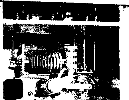 Figure 32 TOP VIEW OF KILOWATT AMPLIFIER USING 4-400A TETRODE Plate circuit inductor is placed parallel to panel and driven by right-angle drive unit. Loading capacitor is at right, with variable vacuum capacitor mounted vertically at rear of chassis. 4-40QA tube and air socket are at rear right corner of chassis, Vfith bias transformer in left corner. Plate blocliing capacitors are placed between aluminum piates and mounted atop vacuum capacitor. Plate r-f choke is hidden between tube and variable vacuum capacitor. At base of capacitor are ihe B-plus VHf filter chokes and bypass capacitors. Meters are isolated by aluminum shield running full length of chassis. Meter leads pass down conduit (left corner) to under-chassis area. Shield plate covers entire enclosure. Figure 33 UNDER-CilASSIS VIEW OF CATHODE-DRIVEN AMPLIFIER Bias and screen supply, and input circuits are placed in the under-chassis area. Filament transformer and filament choke are at left, with tube socket next to the choice. Screen terminals oi socket are grounded with wide aluminum strap passing across terminals ia socket shell and chassis. Grid terminal is bypassed to center of strap. Input capacitors mount between filament terminals and coaxial input receptacle on rear of chassis. At right are power supply compartment (see figure 34} and voltage regulator tubes. Vacuum capacitor gear drive and output circuit voltmeter are at center of chassis. Blower motor is next to filament transformer. Under-chassis area is pressurized sa that air escapes through tube socket vent. After bottom plate is in place, seam around plate is sealed with cellophane tape to provide air-tight enclosure. 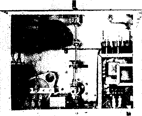 shield is ЭУв high. This shield is made of one piece of aluminum, bent into a U-shape, having 1/2-inch flanges on all sides. The open side of the U is bolted to the front panel as shown in the photographs. Elastic stop-nuts are affixed to the shield every IVi along the flange, or it may be drilled and tapped for 6-32 machine screws. A shield of this type can be homemade, or it may be fabricated in any large sheet metal shop for a small sum. The three indicating meters are mounted on the top front of the panel and are shielded from the intense r.f. field of the amplifier by a half-box section of shielding bent to fit around the rear of the meter cases. The meter shield measures 2У2 deep, AY4 high, and is long enough to make a close fit with the outer shield at each end. Meter leads pass from the under-chassis area through the upper deck via a short section of V2-inch pipe, threaded at each end and bolted between the chasms deck and the meter shield. The major components are mounted with an eye towards panel symmetry and short leads. The vacuum tube socket and variable vacuum capacitor G are placed to the rear of the chassis. The capacitor is mounted in a vertical position, gear driven from the under-chassis area (figure 33). Plate choke RFC-1 is placed between the air socket and the capacitor. Direct- ly in front of the tube is the panel driven 1500 /i/afd. loading capacitor G, mounted on two heavy aluminum brackets, bringing its shaft in line with that of the variable inductor, Li. Plate inductor Li is affixed to the chassis parallel to the front panel, and is driven through a miniature right angle drive, as seen in figure 32, making the control knobs of Li and G occupy symmetrical positions on the panel. The variable vacuum capacitor is centered between the sides of the chassis and is panel driven by a counter dial and a right angle drive unit. To preserve the panel appearance, the counter dial is mounted with its shaft about 2Ц, above the lower edge of the panel. The center-line of the right angle drive unit, however, falls about IVg above the panel edge. Two 11/4 brass gears are used to couple the shafts, as seen in figure 34. The gears are held in position by an angle plate cut from a soft aluminum sheet. The Tube Socket An Eimac air cooled socket is used for the amplifier tube. The small 115 volt a.c. blower motor is mounted near the socket, and the entire under-chassis area is sealed air-tight with a bottom plate. A W wide aluminum strap passes across the center of the socket, extending down 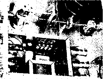 Figure 34 CLOSE-UP OF POWER SUPPLY COMPARTMENT AND GEAR DRiVE SYSTEM Of-cenfer shafts of capacitor and counter dial are ganged by two gears held in position by triangular plate bolted to chassis. Enclosure below holds power supply components. Silicon rectifiers are mounted in fuse clips attached to enclosure wall. All power leads leaving enclosure pass through small, bullt-head-type ceramic capacitors. Primary leads pass through Hypass capacitors an rear wall of chassis. Potentiometers Ri and Ri are in corner of chassis. to the chassis on both sides. This strap is bolr-ed to the two screen terminals of the socket, and to the two diagonal assembly screws of the socket frame. The ends of the strip are fastened to the chassis, forming a low impedance return path for the screen circuit. The .001 jafd., 5 KV ceramic grid bypass capacitor is mounted directly between the ground strap and the grid terminal of the tube socket. The r.f. input jack Ji is mounted to the rear wall of the chassis directly behind the tube socket and two .001 /xfd. ceramic capacitors are connected between the center terminal of Ji and each filament terminal of the tube socket. Short leads connect the filament terminals to the filament choke coil L2 mounted on the side wall of the chassis, directly above the tube socket. The power supply components are encased within an auxiliary shield measuring 5 X 7J4 (figure 34). All leads leaving this enclosure pass through .001 /ifd. ceramic feed-through capacitors mounted on the wall of the enclosure. The four silicon rectifiers are mounted in a multiple fuse clip holder placed on the side wall, and the three regulator tubes are mounted on the adjacent wall. Amplifier Wiring and Tuning The power circuirs of the amplifier may be wired with unshielded wire since the r.f. field beneath the chassis is extremely low. All d.c. leads are cabled and laced as may be seen in the under-chassis photograph. Leads to the meter deck pass through the area above the chassis in a short section of V2-inch alum- inum conduit, and each meter is bypassed as shown in the schematic. Small insulated tip jacks (Je-Jio) are mounted on the rear of the chassis to facilitate voltage measurements. In addition, two insulated, closed-circuit jacks (Ji, J5) allow the voltage regulator currents to be read. Choke coils RFC-2 are wound on a -g-inch wooden dowel rod which is removed, leaving the coils self-supporring. Plate circuit wiring above the deck is done with silver plated copper strap. When the amplifier wiring is completed the power supply should be checked. The regulator tubes are inserted in the correct sockets and the current flowing through the regulator circuit is measured. The 1500 ohm series resistor in the power supply is adjusted to provide 40 milliamperes of screen regulator current. If the correct current value is obtained with less ;han 500 ohms of series resistance, the I /xfd. input filter capacitor should be increased in value to 8 /xfd. to boost the supply voltage. The regulator current divides between the VR-75 and the bias adjust potentiometer Ri, and 25 milliamperes of regulator current is measured at Js when the supply is adjusted for 40 ma. at jack Jj. After final adjustment has been completed, the variable series resistor in the supply may be replaced with a fixed one if desired. Finally, bias control potentiometer Ri is set for -60 volts as measured between Ju (minus) and Jc (plus). Switch S2 should be placed in the tune Figure 35 GENERAL PURPOSE AMPLIFIER OPERATES IN CLASS A, B, OR С MODE rhis kilowatt amplHier employs a pair of 4-2S0As in a pi-network circuit. Mode of operation may be set by selection of proper screen and bias voltages. Grid, plate, and screen current meters are mounted on plastic plate behind panel cut-out, and tubes are visible through shielded panel opening. Across bottom of panel (left to right) are band-switch, grid tuning, plate tuning, loading, and primary power control circuits. Plate tuning knob is attached to small counter dial. position before voltages are applied to the tube. A suitable antenna load should be placed on the amplifier; bias, screen, and plate voltage are applied. The bias control should be varied slightly to produce the correct resting plate current as indicated in figure 30. Excitation should never be applied without plate voltage on the amplifier, or without an external antenna load, since the resultant high grid and screen current would damage the tube. In addition, screen voltage should never be applied without plate voltage. The combination screen and bias supply of the amplifier is designed to be turned on with the plate supply through the relay control terminal. All voltages may be left on the amplifier during VOX operation, or the supplies may be turned on by the VOX circuit. The tune-Operate switch Sj should not be thrown when excitation is applied to the tube, since the momentary breaking of the screen to ground path will apply the full excitation power to the control grid of the tube during the moment the switch is in transition from one position to the other. In practice, this switching action has been done with full excitation applied to the tube, but it is not recommended. The exciter should now be connected and a small amount of carrier is inserted. The plate resonant point is found with tuning capacitor Ct and the ampHfier loading adjustments are made, gradually increasing the excitation and loading until the single tone conditions outlined in figure 30 are met. Speaking into the microphone should produce approximately the same peak conditions as obtained with carrier insertion. The linearity of the amplifier may be checked with the use of two envelope detectors as described in an earlier chapter. 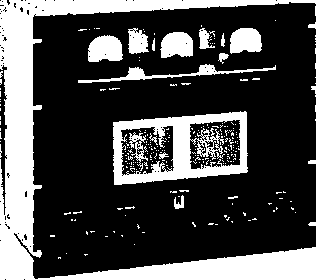 29-9 Kilowatt Amplifier for Linear or Class С Operation A pair of 4-250A or 4-400A tetrode tubes may be employed in a pi-coupled amplifier capable of running one kilowatt input, c-w or plate modulated phone, or two kilowatts p.e.p. for sideband operation. Correct choice of bias, screen, and exciting voltages will permit the amphfier to function in either class A, Б, or class С mode. The amplifier is designed to operate at plate potentials up to 4000 volts, and excitation requirements for class С oper-arion are less than 25 watts. A bandswitching type of pi-network is employed in the plate circuit of such an amplifier, shown in figure 35. The pi-network is an effective means of obtaining an impedance match between a source of r.f. energy and a low value of load impedance. A properly designed pi-nerwork is capable of transformation ratios greater than 10 to 1, and will provide approximately 30 decibels or more attenuation to the second harmonic output of the amplifier as compared to the desired signal output. Since rhe second harmonic level of the amplifier tube may already be down some 20 db, the actual second harmonic output of the network will be down perhaps 50 db from the fundamental power level of the transmitter. Attenuation of the third and higher order harmonics will be even greater. OUTPUT S2B J2 Ll L2 L3 L4 Ls NOTEl SCffFEN BYPASS CAPACITORS ARE CENTRALAB TYPE 858 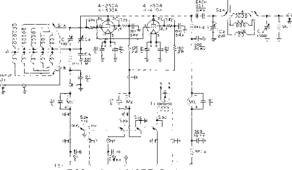 -BIAS CON- -l-SCREEN SND TROL 115V. llSif, B+2500-. Figure 36 SCHEMATIC, GENERAL PURPOSE KILOWATT AMPLIFIER Cl-700 niifd. Hammar-lund HF-rOO Cl-200 fiiifd., lOKV variable vacuum capacitor. Jennings UCS-200 Сз-1500 fiiifd., variable capacitor. Cardwell 8013 Cl,-Neutralizing capacitor, disc. Millen 15011 Cs-300 iififd., mica, 1250 volt Li-L,o-See coil table, figure 39 PC-47 ohm, 2 watt composition resistor wound with 6 turns #78e. RFCi-2.5 mh. choke. National R-100 RFCi-Heavy duty, wideband r.f. choke. Barker & Williamson type 800 RFC-VHF choke. Ohmite Z-144 Si-Tivo pole, 6 position switch. Two Centralab PA-17 decks, with PA-301 index assembly Si-Two pole, 6 position high voltage switch. Communication Products Co. type 88 two gang switch Sj-four pole, three position switch. Centralab Tl-5 volt, 20 ampere. Stancor P-6492 M,-0 - SO Tripiett d.c. Mi-0 - 750 ma. d.c. Tripiett Мз-0 - 750 ma. d.c. Tripiett Gears-2 required. Boston Gear #G-46S and #G-466 The peak voltages encountered across the input capacitor of the pi-network are the same as would be encountered across the plate tuning capacitor of a single-ended tank used in the same circuit configuration. The peak voltage to be expected across the output capacitor of the network will be less than the voltage across the input capacitor by the square root of the ratio of impedance transformation of rhe network. Thus if the network is transforming from 5000 ohms to 50 ohms, the ratio of impedance transformation is 100 and the square root of the ratio is 10, so that the voltage across the output capacitor is 1/10 that across the input capacitor. A considerably greater value of maximum capacitance is required of the output capacitor than of the input capacitor of a pi-network when transformation to a low impedance load is desired. For 3.5 Mc. operation, maximum values of output capacitance may run from 500 fififd. to 1500 jajafd., depending upon the ratio of transformation. Design information covering pi-network circuirs is given in an earlier chapter of this Handbook. Illustrated in figures 35-41 is an up-to-date version of an all-band pi-network amplifier, suited for sideband or class-C operation. The unit is designed for TVI-free operation over this range. Circuit The schematic of the general Description purpose amplifier is shown in figure 36. The symmetrical panel arrangement of the amplifier is shown in the front view (figure 35) and the rear view (figure 37). A 200 fififd. variable vacuum capacitor is employed in the input side of the pi-network, and a 1500 fififd. variable air capacitor is used in the low impedance output side. The coils of the network are switched in and out of the circuit by a two pole, five Figure 37 REAR VIEW OF GENERAL PURPOSE AMPLIFIER WITH SHIELD REMOVED The pl-network circuit is built from an inexpensive high voltage rotary switch, and five inductors. The switch is panel driven by a gear and shaft system shown in figure 38. Variable vacuum capacitor is mounted vertically between the tubes, directly in back ot the plate r.f. choke. Neutralizing capacitor is ot right, connected to plates of tubes with a wide, silver plated copper strap. Meters are encfosed by aluminum shield partition running the width of the enclosure, with conduit carrying meter loads to under-chassis area at left, front of chassis. Metal shells of tube bases are grounded by spring contacts. position highi voltage ceramic rotary switch. Each coil is adjusted for optimum circuit Q, resulting in no tank circuit compromise in efficiency at the higher frequencies. A close-up of the tank circuit is shown in the introductory photograph at the chapter head, and complete coil data is given in figure 39. The plate blocking capacitor is made of two .001 fiid., 5 KV ceramic capacitors connected in series. Special precautions are taken to insure operating stability over the complete range of amplifier operation. The screen terminals of each tube socket are jumpered together with Ys copper strap and a parasitic choke (PC) is inserted between the center of the strap and the screen bypass capacitor. In addition, sup- 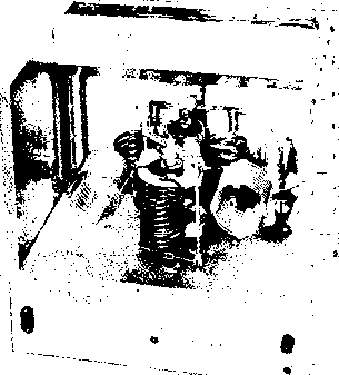 pressor resistors are placed in the screen leads after the bypass capacitor to isolate the sensitive screen circuit from the external power leads. A third parasitic choke is placed between the grid terminals of the tubes and the tuned grid circuit. The five coils of the grid circuit are enclosed in a small aluminum shield placed adjacent to the tube sockets (figure 38 and figure 40). The amplifier is neutralized by a capacitive bridge system consisting of neutralizing Figure 38 PLACEMENT OF PARTS IN UNDER-CHASSIS AREA Grid tuned circuit is enclosed in separate enclosure at left. Bandswitch projects out the rear of case, and is gear driven by same shaft that actuates the plate band-switch. Switches are driven through right-angle gear drives and gears. Output capacitor of pi-network is shielded from rest ot under-chassis components. The screen terminals of each tube socket are strapped together with Уа copper ribbon, and low inductance screen bypass capacitor is grounded t о socket mounting bolt. Screen parasitic choke mounts between strap and capacitor terminal. All power leads beneath the chassis are run in shielded braid, grounded to chassis at convenient points. B-plus lead is made of section ot RG-8/U coaxial cable, with outer sheath and braid removed. 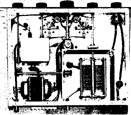
capacitor Ci and G>, the grid circuit bypass capacitor. Screen voltage may be removed for tune-up purposes by control switch Sh section B. The screen circuit is grounded in the off and fil positions by means of switch section C. Amplifier The complete amplifier is Construction built upon an aluminum chas- sis measuring 13 x 17 x 3 and has a 14 standard relay rack panel. The 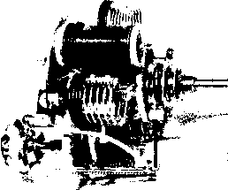 Figure 40 GRID TANK CIRCUIT ASSEMBLY Coi/s are mounted fo fhe ceramic switch decks by iheir leads. A small aluminum plate attached to rear of tbe switch assembly rods supports grid tuning capacitor which projects out rear of shielded enclosure. Entire assembly may be pre-wired before placing in enclosure. grid circuit components are mounted within an aluminum box measuring 3 x 4 x 4 . Plate loading capacitor G, r.f. choke RFC-1, and output connector Jj are placed within an enclosure measuring 6 x 6 x 3 , made up of aluminum angle sections and sheet material. The plate circuit shielding is made of Reynolds Do-it-yourself aluminum stock, available ar most hardware stores. Layout of the major components can be seen in figure 37. The two tube sockets are placed directly behind the panel opening, with the plate r.f. choke between them, and the variable vacuum capacitor is mounted vertically to the chassis directly behind the sockets, on the center line of the chassis. To the right of the sockets is neutralizing capacitor C. The high voltage ceramic coil switch SA-B is placed directly behind the vacuum capacitor, mounted in a vertical position. The variable vacuum capacitor is panel driven by a counter-type dial, through a miniature right angle gear drive, as seen in the under-chassis view (figure 38). The plate and grid band switches are ganged and switched in unison by means of a shaft acting through two right angle gear drives and two bevel gears. Both circuits are thus switched by the Band-switch control located in the lower left corner of the front panel. It is necessary to apply forced air to the sockets of the amplifier tubes. A large 115 volt a.c. operated blower is therefore mounted in the center of the bottom shield plate. The under-chassis area is thus pressurized and the majority of the air escapes through the socket ventilation holes located near the pins of the tubes. All wiring beneath the chassis (with the exception of the filament leads) is done with 5KV insulated wire, encased in metallic braid which is grounded to the chassis every inch or so. The B-plus wiring from the high voltage terminal to the plate current meter is done with a section of RG-8/U coaxial line from which the outer braid has been removed. A similar piece of line is run from the meter to the plate r.f. choke, RFG2. The three meters are mounted upon a lu-cite sheet placed behind a second lucite sheet mounted behind a cut-out in the front panel. The meters are shielded from the plate circuit of the amplifier by an aluminum enclosure that covers the wiring and meters, running the full length of the chassis. The meter leads pass through the plate circuit area via a short length of 1/2-inch aluminum conduit that is threaded 4-250A/4-400A OPERATING CHARACTERIST (г TUBES ) ITEM SSB#1 30OO MODE ;ГВв2 PHONE 30OO , 2500 PLATE VOLTAGE PLATE CURRENT [MA), 1 1 0-420 260-440Д 400 SCREEN VOLTAGE 600 500 500 SCREEN CURRENT {MA )] 24 1.0 I 60 110 -80 -2 00 -110 -ao I -120 0 I 0 ; 20 GRID BIAS PROTECTIVE BIAS GBl D CURRENT (мА.) POWER OUTPUT {WATTS) J 3000 330 70 -200 -120 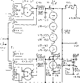 Figure 41 OPERATING DATA AND SCHEMATIC, SCREEN AND BIAS SUPPLY T,-870.410.0-410870 volts at ISO mo. and 60 ma. S volts, 2 a., 6.3 v. 3.S a. Stancor P-8307 Тг-235-0-235 volts at 40 ma. Stancor PC-8401 CHi-7 henry ot ISO ma. Stancor C-I7I0 СНг-7 henry at 50 mo. Stancor C-I707 RYi-Overload relay, adjustable 100-2S0 ma. Note: J. is insulated from chassis. at each end and bohed to the chassis and the meter shield. Plate circuit wiring above the chassis is done with V-inch silver plated copper strap as seen in the introductory photograph at the beginning of this chapter. Amplifier After the amplifier is wired Neutralization and checked, it should be neutralized. This operation can be accomplished with no power leads attached to the unit. The tubes are placed in their sockets, and about 10 watts of 30 Mc. r.f. energy is fed into the plate circuit of the amplifier, via the coaxial output plug J. The plate and grid circuits are resonated to the frequency of the exciting voltage with the aid of a grid-dip meter. Next, a sensitive r.f. voltmeter, such as a 0 - 1 d-c milliammeter in series with a 1N34 crystal diode is connected to the grid input receptacle (Ji) of the amplifier. The reading of this meter will indicate the degree of unbalance of the neutralizing circuit. Start with a minimum of applied r.f. excitation to avoid damaging the meter or the diode. Resonate the plate and grid circuits for maximum meter reading, then vary the setting of neutrahzing capacitor C4 unril the reading of the meter is a minimum. Each change in C4 should be accompanied by re-resonating the grid and plate tank circuits. When a point of minimum indication is found, the capacitor should be locked by means of the auxiliary set screw. Complete neutralization is a function of the efficiency of the screen bypass system, and substitution of other capacitors for those noted in the parts list is not recommended. Mica, disc-type, or other form of bypass capacitor should not be substiruted for the units specified, as the latter units have the lowest value of internal inductance of the many types tested in this circuit. Bias and The amplifier requires -60 to Screen Supply -110 volts of grid bias, and plus 300 to 600 volts of screen potential for optimum characteristics when working as a class ABl linear amplifier. Screen voltage for class С operation (phone) is 400 volts. The voltage may be raised to 500 volts for c.w. operation, if desired, although the higher screen voltage does Uttle to enhance operation. Approximately -120 volts cut-off bias is required for either phone or c-w operation. A suitable bias and screen power supply for all modes of operation is shown in figure 41, together with an operating chart for all operating voltages. The supply furnishes slightly higher than normal screen voltage which is dropped to the correct value by an adjustable series resistor, Ri. This series resistor is adjusted for 30 milliamperes of current as measured in meter jack Ji when the supply is disconnected from the amplifier. Series bias resistor R2 is adjusted for the same current in jack J:; under the same conditions. The value of protective bias may now be set by adjusting potentiometer Ra. Additional bias is required for class С operation which is developed across series resistor Rl. Switch Sl is open for class С operation and closed for sideband operation. It is imperative that the screens of the tet- 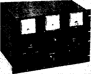 rode amplifier tubes be protected from excessive current tbat could occur during tuning adjustments, or during improper operation of the amplifier. The safest way to accomplish this is to include an overload relay that will open the screen circuit whenever the maximum screen dissipation point is reached. Two 4-250A tubes or 4-400A tubes have a total screen dissipation rating of 70 watts, therefore relay RY-I should be adjusted to open the screen Figure 42 4CX-1000A ALL BAND AMPLIFIER PROVIDES TWO KILOWATT P.E.P. FOR SIDEBAND, OR ONE KILOWATT FOR PHONE C.W. OPERATION Grid, plate, and output meters are across top af panel. Counter dial at center drives variable vacuum tuning capacitor, with loading control directly beneath it. Meter switch is ot left, with bandswitch at right. Entire amplifier is screened to reduce unwanted radiation. circuit whenever the screen current reaches ap?roximately 100 milliamperes. 29-10 A 2 Kilowatt P.E.P. All-band Amplifier Described in this section is an efficient all-band linear amplifier suited for SSB, phone, and c.w. operation up to the maximum legal power input limit. A 4CX-1000A ceramic power tetrode is employed in the basic circuit shown earlier in this chapter in figure IIC. The Eimac 4CX-I000A is a ceramic and 4сл- loooa input j 1 ©-- 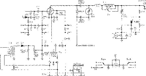 llSV -l-SCR B- GND, Figure 43 SCHEMATIC, 4CX-I000A LINEAR AMPLIFIER C,-500 fi/jfd., 10KV variable vacuum capacitor. Jennings UC5L 4-500 C..- ISOO iififd. Cardwell 8013 L,-Si-High-C, all-band turret. Barlier & Williamson 852 RFCj-2.5 mh. National R-lOO RFCj-Heavy duty plate choke. Raypar RL-100 Tl-6 volts, 12.5 amperes, with primary taps. Stancor P-6463 T,-125 volts, IS ma. Stancor PS-8415 Rl-100 ohm, 20 watt non-inductive resistor. May be made of a number of 2 or 4 watt composition resistors connected in series parallel. Two Sprague type NIT, 10 watt Cool-ohm 200 ohm resistors in parallel used. Ml, Ms-0 - 7 d.c. milliammeter Mi-0 - J d.c. ammeter Eimac SK-800 air socket 1 ... 60 61 62 63 64 65 66 ... 80 |
|||||||||||||||||||||||||||||||||||||||||||||||||||||||||||||||||||||||||||||||||||||||
|
© 2026 AutoElektrix.ru
Частичное копирование материалов разрешено при условии активной ссылки |