 |
 |
 |
| Главная Журналы Популярное Audi - почему их так назвали? Как появилась марка Bmw? Откуда появился Lexus? Достижения и устремления Mercedes-Benz Первые модели Chevrolet Электромобиль Nissan Leaf |
Главная » Журналы » Simple coaxial reflectometer 1 ... 61 62 63 64 65 66 67 ... 80 Figure 44 END VIEW OF AMPLIFIER 4CX-1000A sub-chassis is shown, with plate circuit choke mounted at rear. Cxternal blower provides forced air to cool tube seals via entrance hole in rear of chassis. Bias adjustment potentiometer is in foreground, between tube and meter switch. metal, forced air-cooled, radial beam tetrode with a rated maximum plate dissipation of 1000 watts. It is a low voltage, high current tube specifically designed for class ABl r-f linear amplifier service where its high gain and low distortion characteristics may be used to advantage. At its maximum rated plate voltage of 3000, it is capable of producing 1680 watts of single-tone output power in SSB service. Maximum grid dissipation of the 4CX-100OA is zero watts. The design features which make the tube capable of maximum power operation without driving the grid into the positive region also make it necessary to avoid positive grid operation. Circuit The circuit of the all-band am- Description pHfier is shown in figure 43. A resistance loaded, untuned grid input circuit is employed in conjunction with a pi-network plate output circuit. Grid driving requirements are 60 volts peak across resistor R) which has a value of 100 ohms. This corresponds to 36 watts p.e.p. all of which is dissipated in resistor Ri. For normal voice operation, a 20 watt non-inductive resistor may be used. A simple 1N66 diode voltmeter is incorporated in the grid circuit to monitor the excitation voltage. Grid and screen current are also measured. The d.c. grid bias voltage is obtained from a small selenium-type half-wave power supply contained within the amplifier. The plate circuit is designed around the new Barker & Williamson type 852 bandswitching turret, especially designed for high current, low voltage tubes of this type. The input tuning capacitor of the network is a 500 /i/fd. variable vacuum unit, and the output loading control is a 1500 ;x;afd. variable air capacitor. For operation into low impedance loads in the 80 meter band, an additional 1500 jit/xfd. fixed mica capacitor may be placed in parallel with the output loading capacitor, G. A second 1N66 diode voltmeter is placed across the output circuit as a tuning aid. 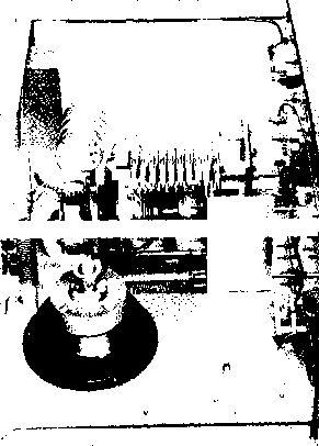 Screen Grid Tetrode tubes may exhibit re-Operation versed (negative) screen current to a greater or lesser degree depending upon individual tube design. This characteristic is prominent in the 4CX-1000A and, under some operating conditions, indicated negative screen current of the order of 25 milliamperes may be encountered. In general, high values of negarive screen current wiU be measured at the lower values of plate potential. It is difficult to measure screen dissipation in the presence of secondary emission of this type. The usual product of current and voltage may not provide an accurate picture of actual screen dissipation. Experience has shown that the screen will operate within the limits established for this tube if the indicated screen current, plate voltage, and drive voltage approximate the values given in the operating chart of figure 48. The screen supply voltage must be maintained constant for any values of negative and positive screen current that may be encountered. Dangerously high plate currents may flow if the screen power supply exhibits a rising voltage characteristic with negative screen cur- rent. Stabilization may be aaomplished in several ways. A combination of voltage regulator tubes may be connected across the screen supply, or a heavy bleeder resistor may be placed across the supply that will draw approximately 70 milliamperes at the operating potential of the screen. Screen voltage is not particularly critical, especially at plate potentials of 2500 volts and higher. However, the screen voltiige should be adjusted for best linearity of the stage when the tube is operated at 2000 volts plate potential. A 350 volt, 150 ma. supply utilizing choke input and bled to 70 milliamperes, in conjunction with a 100 watt primary Variac or variable voltage transformer is a satisfactory source of screen voltage. Three VR-105 regulator tubes passing 40 ma. may be employed for a fixed-voltage screen supply. Amplifier Layout of the amplifier may ConstrucWon be seen in figures 42, 44, 45, 46, and 47. A I21/4 x 19 rack panel is employed to form the front of an enclosure 14 deep. The enclosure is built of 1/5-inch aluminum angle stock and the top, sides and back are covered with perforated aluminum sheet. The bottom of the enclosure is formed from a solid sheet of aluminum. Only a very small chassis is required to mount the 4CX-1000A tube socket, filament transformer, and grid circuit components. A chassis measuring 6 x 3 x 14 with one end cut off is employed (figure 47). This chassis is mounted at one end of the enclosure and supports a small aluminum angle bracket holding the two pi-nerwork capacitors. The band-swirching plate tank inductor is mounted di- 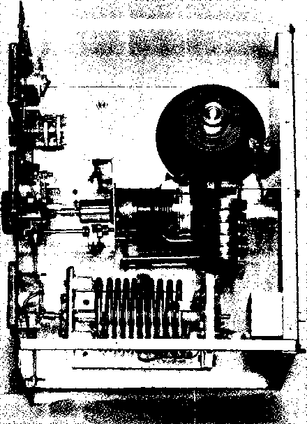 Figure 45 TOP VIEW OF 4CX-1000A AMPLIFIER Tetrode tube fits in Eimac air socfcet on small chassis at one end of enclosure. Pi-network capacitors are mounted on aluminum bracket attached to chassis, and are panel driven through flexible shaft couplers. Heavy duty, bigh-C band-switching inductor is at opposite side of assembly, with output circuit diode voltmeter mounted above it on rear of enclosure. Extremely low harmonic content of amplifier removes need of meter shields. Amplifier may be run without enclosure with no sign ot TYI on any band in normal TV signal area. Figure 46 REAR VIEW OF CHASSIS ASSEMBLY Air inlet, power receptacle and coaxial input iacic are located on rear of amplifier chassis. Pi-networit capacitor assembly is at left, with Raypar wideband plate r-f choice in tore-ground. Plate blocking capacitor is made of tour 500 iititd. TV-type capacitors mounted in sandwicfi between stator i>late of vacuum capacitor and round aluminum plate. rectly to the aluminum bottom plate of the enclosure as seen in figure 45. The low impedance plate tank circuit requires a higher than normal value of plate coupling capacitor. Four 500 fifj-id., 20 KV TV-type capacitors are therefore mounted between two aluminum plates to form a 2000 /xju-fd. sandwich which is bolted to the rear stator terminal of tuning capacitor &. The 10 meter inductor section of coil Li bolts directly to the aluminum plate, as does the plate lead of the 4CX-1000A. Special breechlock terminal surfaces are used on the tube in place of the convention! 1 base. Three tabs protrude through the ceramic envelope for each tube element, providing a low inductance termination. The new Eimac SK-800 socket having a built-in screen bypass capacitor and an air vent should be employed with this tube. The rated heater voltage for the 4CX-1000A is 6.0 volts and the operating voltage, as measured at the socket, should be maintained within plus or minus 5% of this value if long life operation is to be obtained. Note that the cathode and one side of the heater are Internally connected. Sufficient cooling must be provided for the anode and ceramic-to-metal seals to maintain operating temperatures below 200 degrees, Centigrade. At sea level, with an inlet air temperature of 20 °C., a minimum of 35 cubic feet per minute of air flow is required. In this case, the chassis is pressurized and a 50 cubic foot/minute blower is connected to the air inlet on the rear of the chassis by means of a short length of automobile radiator hose. The cooling air must be maintained on the ceramic seals during standby periods when only heater voltage Is applied to the tube. Figure 47 UNDER-CHASSIS VIEW OF 4CX-1000A AMPLIFIER Bias supply is placed at one end of chassis. Filament transformer is mounted next to air socket and short, heavy strap leads are used to eliminate voltage drop. Special air socket has built-in screen bypass capacitor to ensure low inductance ground path. 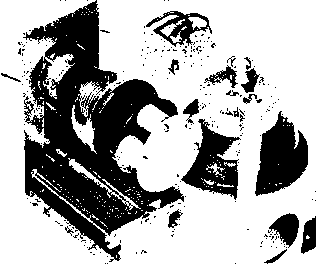 Amplifier Amplifier operating characteris-Operation tics are given in figure 48. The bias potentiometer R2 Is adjusted to provide a zero-signal plate current of 250 milliamperes, At this value, the bias voltage will be approximately -55 volts. Resting plate current and screen voltage may both be varied over small limits to provide the greatest Hn-earity range. Maximum single tone plate current is 1.0 ampere. Good linearity may be obtained at 2000 watts p.e.p. at a plate voltage of 2500 and maximum plate current of 800 ma. Care should be taken not to apply excitation to the amplifier in the presence of screen voltage but with no plate voltage present. A relay interlock may be applied to the screen circuit to open it in the absence of plate voltage. Grid exciting voltage should be limited to about 60 volts, and grid current should be monitored to see that it does not exceed 0.5 milliamperes during tune-up. 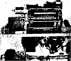 FIGURE 48 OPERATING CHARACTERISTICS, 4СХ-1000А AMPLIFIER
NOTE: adjust SKIO VOLTaS£ to obtain specified ZERO-signal plate uurrent. 29-n A High Power Push-pull Tetrode Amplifier The push-puh tetrode amphfier stiU retains a high degree of popularity in spite of the trend towards single-ended pi-networlc amplifiers. Regardless of the power level of the push-pull amplifier, the physical design must satisfy two important requirements. First, the plate and grid circuirs of the amplifier must be symmetrical with respect to each tube; and second, the input and output circuits must be isolated from each other. Finally, after the physical layout of the amplifier has been de-  © О  termined, steps must be taken to eliminate all tendencies towards parasitic oscillation. Described in this section is a push-pull amplifier intended for operation in the 13-15 Mc. region. Push-pull 4-lOOOA tubes are employed, running at their maximum rated input. Other tubes, such as the 4-400A, 4-250A, or 4-125A may be substituted in the design, scaling down the various components to suitable sizes for the reduced power level. This amplifier design is suitable for use in the 3 - 30 Mc. frequency region. The lower limit of operation is restricted by the amount of tuning capacity in the grid and plate tank circuits. Padding capacitors placed across the variable tuning capacitors may be employed to reach the lower frequency portions of the HF spectrum. The upper frequency limit of operation is determined by the residual screen lead inductance of the particular tubes used in the circuit. At frequencies up to 30 Mc, no neutralizing difficulties are encountered with any of the previously mentioned tubes. Circuit The complete schematic of the Description push-pull tetrode amplifier is shown in figure 50. Grid, filament, and auxiliary metering circuits of the amplifier are enclosed beneath the chassis in an electrically tight box. All leads leaving this box are suitably filtered to prevent leakage of energy into (or out of) the enclosure. The plate circuit of the amplifier is contained in a separate enclosure above the main chassis. A small degree of feedback exists within the tetrode tubes due to the minute value of grid-plate capacity. It is therefore necessary to cross-neutralize the tubes by means of two capacitor tabs mounted near the envelope of the tube (figure 53). These capacitors are adjusted for minimum r-f feedback at the highest operating frequency of the amplifier. Any tendency towards parasitic oscillation is eliminated by the use of small parasitic chokes placed in the grid and screen leads of each tetrode tube. Excellent parasitic suppression is achieved by strapping the screen ter- Figure 49 HFGH POWER PUSH-PULL AMPLIFIER USES 4-lOOOA TUBES This amplifier design is typical of push-pull stages regardless of power level. Tubes are visible through screened openings in panel. Controls are (top to bottom): Output link tuning, variable link coupling, plate circuit tuning, and grid circuit tuning. Amplifier is housed in special 21 rack. Filament meters for each tube are on auxiliary panel holding bias and screen supply. и C2 4-ю00а/4-400а 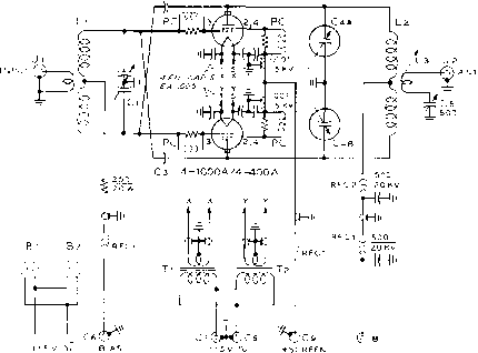 note: 1. scpee/v bypass Capacitors ARE СЁrjTRALAB TyPE ai8 Figure 50 SCHEMATIC, PUSH-PULL HIGH POWER AMPLIFIER Ci-700 - JOO lififd. butter-fly capacitor. Barker & Williamson type JCX Сг, Cj-Neutralizing capacitors. I x 3 aluminum plate mounted near tube envelope (figure S3) C,A-B-60 - 60 ii/ifd. split-stator variable vacuum capacitor. Cimac YYC-60-20. See text tor substitute С,-500 ii/ifd. Johnson S00E20 Cr,-C!,-0.7 iitd., 600 volt feedthraugli capacitor. Centralab HY-pass RFC,-VHF-type choke. National R-60, ar Ohmite Z-50 RFC2-Heavy duty plate choke. Surplus choke from AN/ART-13 transmitter, or Barker & Williamson type 800 PC-Parasitic suppressor. 3 turns #14 wire, /i-inch diam. in parallel with 47 ohm, S watt carbon Globar resistor minals of the tetrode socket together (figure 52) and inserting a parasitic choke between the screen terminal of the socket and the screen bypass capacitor. Eimac air sockets should be employed with the larger tubes, and a blast of air directed at the base seal of each tube is required. Two small 115-volt blower motors mounted on the rear of the chassis direct air streams through sections of radiator hose to the two tube sock- Figure 51 REAR VIEW OF AMPLIFIER Plate tank circuit is placet! between tetrode tubes which are mounted in air sockets. Split-stator variable vacuum capacitor is panel mounted and rotors are grounded to chassis by heavy copper strap. Tank coil is mounted on 10 ceramic insulators. Individual filament transformers tor the 4-lOOOA tubes are at rear of chassis. Each tube requires 7.5 volts at 21 amperes. Swinging link is panel driven through Millen right-angle drive unit, and flexible, braided leads connect link to antenna resonating capacitor and coaxial receptacle mounted in top screen of amplifier. Dual blower motor is mounted to rear of chassis. All power leads (including filament leads to meters) are brought out through bulkhead-type capacitors. 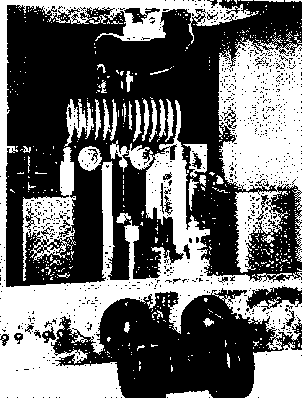 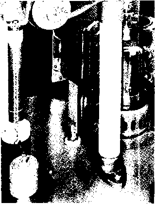 ets. It is necessary to ground the metal base ring of each tube to the chassis, since this ring forms part of the scteen shielding circuit. If grounding clips are not furnished with the tube socket, they may be made from a short length of ys-inch wide brass strap formed to spring against the base ring. Excellent circuit symmetry is achieved by the use of butter-fly -type tuning capacitors in the grid and plate circuits. A 100-watt plug-in coil may be employed in the grid circuit, while heavy-duty plug-in coils will suffice in the plate circuit up to the kilowatt level. If extremely high plate voltage is to be used, the Eimac dual vacuum variable capacitor (VVC-60-20) should be employed to prevent flash-over. The less expensive Barker & Williamson butter-fly capacitor may be employed for plate voltages of 3500 or less. 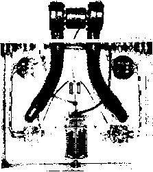 Figure 53 CLOSE-UP OF PLATE CHOKE AND NEUTRALIZING CAPACITOR Neuiralmng capacitor is made of tab soldered io threaded rod mounted in insulating button affixed to chassis. Amplifier If 4-250A or 4-125A tubes Construction are employed, a 15 x 17 x 6 chassis may be used. The 4-lOOOA tubes require a 17 x 19 x 6 chassis. Panel height is determined by the components mounted above the chassis deck. The top of the amplifier compartment should clear the plate coil by at least the diameter of the coil to prevent flash-over and to hold the coil Q to the highest possible value. The amplifier enclosure is made of Vi-inch aluminum angle stock covered with perforated aluminum. The under-chassis area of the amplifier is sealed with a piece of solid aluminum sheet. Plate circuit wiring is done with V-inch silver plated copper strap, and for the higher power levels all connections in this circuit should either be bolted or silver-soldered. All grid circuit wiring is done with #10 copper wire, and all low voltage d.c. leads and a.c. wiring is done in shielded braid, rhe braid being grounded to the chassis at each end of the lead. A short length of RG-8/U coaxial line is used for the connection between the coaxial input plug and the link circuit of the grid coil. The reactance of the antenna link is tuned out by means of a 500 ju.ju.fd. variable capacitor placed in the ground return of the link line. This capacitor is adjusted for maximum loading with the loosest possible degree of link coupling to the amplifier tank coil. Amplifier Excitation and grid bias are ap-Operotion plied to the amplifier and a flashlight lamp is connected to the link output conneaions. The neutralizing tabs are varied in position with respect to the envelope of the tube after the grid and plate circuits have been mned to resonance. Adjustments are made to the capacitors until the degree of feedback is reduced to a minimum. Figure 52 UNDER-CHASSIS AREA OF PUSH-PULL AMPLIFIER Blower motors are connected to air sockets by short lengths of radiator hose. Filament leads are run in braid, grounded at each end. Shield plate is used over bottom of chassis to provide electrically tight enclosure. Screen terminals of each socket are strapped together, and choke PC attaches to center of strap. - ..k CHAPTER THIRTY Speech and e Modulation Equipment Amplitude modulation of the output of a transmitter for radiotelephony may be accomplished either at the plate circuit of the final amplifier, commonly called high-level AM or simply plate modulation of the final stage, or it may be accomplished at a lower level. Low-level modulation is accompanied by a plate-circuit efficiency in the final stage of 30 to 45 per cent, while the efficiency obtainable with high-level AM is about twice as great, running from 60 to 80 per cent. Intermediate values of efficiency may be obtained by a combination of low-level and high-level modulation; cathode modulation of the final stage is a common way of obtaining combined low-level and high-level modulation. High-level AM is characterized by a requirement for an amount of audio power approximately equal to one-half the d-c input to the plate circuit of the final stage. Low-level modulation, as for example grid-bias modulation of the final stage, requires only a few watts of audio power for a medium power transmitter and 10 to 15 watts for modulation of a stage with one kilowatt input. Cathode modulation of a stage normally is accomplished with an audio power capability of about 20 per cent of the d-c input to the final stage. A detailed discussion of the relative advantages of the different methods for accomplishing amplitude modulation of the output of a transmitter is given in an earlier chapter. Two trends may be noted in the design of systems for obtaining high-level AM of the final stage of amateur transmitters. The first is toward the use of tetrodes in the output stage of the high-power audio amplifier which is used as the modulator for a transmitter. The second trend is toward the use of a high-level splatter suppressor in the high-voltage circuit between the secondary of the modulation transformer and the plate circuit of the modulated stage. 30-1 Modulation Tetrode In regard to the use of terrodes, Modulators the advantages of these tubes have long been noted for use in modulators having from 10 to 100 watts output. The 6V6, 6L6, and 807 tubes have served well in providing audio power outputs in this range. Recently the higher power tetrodes such as the 4-65A, 813, 4-125A, and 4-250A have come into more general use as high-level audio amplifiers. The beam tetrodes offer the advantages of low driving power (even down to zero driving power for many applications) as compared to the moderate driving power requirements of the usual triode tubes having equivalent power-output capabilities. On the other hand, beam tetrode tubes require both a screen-voltage power supply and a grid-bias source. So it still is expedient in many cases to use zero-bias triodes or even 5612 low-mu triodes sucli as the 304TL in many modulators for the medium-power and high-power range. A list of suggested modulator combinations for a range of power output capabilities is given in conjunction with several of the modulators to be described. Increasing fhe Effective Modulation Percentage It has long been known that the effective modulation percentage of a transmitter carrying unaltered speech waves was necessarily limited to a rather low value by the frequent high-amplitude peaks which occur in a speech waveform. Many methods for increasing the effective modulation percentage in terms of the peak modulation percentage have been suggested in various publications and subsequently tried in the field by the amateur fraternity. Two of the first methods suggested were Automatic Modulation Control and Volume Compression. Both these methods were given extensive trials by operating amateurs; the systems do give a degree of improvement as evidenced by the fact that such arrangements still are used in many amateur stations. But these systems fall far short of the optimum because there is no essential modification of the speech waveform. Some method of actually modifying the speech waveform to improve the ratio of peak amplitude to average amplitude must be used before significant improvement is obtained. It has been proven that the most serious effect on the radiated signal accompanying over-modulation is the strong spurious-sideband radiation which accompanies negative-peak clipping. Modulation in excess of 100 per cent in the positive direction is accompanied by no undesirable effects as far as the radiated signal is concerned, at least so long as the linear modulation capability of the final amplifier is not exceeded. So the problem becomes mainly one of constructing a modulator-final amplifier combination such that negative-peak clipping (modulation in excess of 100 per cent in a negative direction) cannot normally take place regardless of any reasonable speech input level. Assymetricol The speech waveform of the Speech normal male voice is charac- terized, as was stated before, by high-amplitude peaks of short duration. But it is also a significant characteristic of this wave that these high-amplitude peaks are poled in one direction with respect to the average amplitude of the wave. This is the lopsided or assymetrical speech which has been discussed and illustrated in an earlier chapter. The simplest method of attaining a high average level of modulation without negative peak clipping may be had merely by insuring that tbese high-amplitude peaks always are poled in a positive direction at the secondary of the modulation transformer. This adjustment may be achieved in the following manner: Couple a cathode-ray oscilloscope to the output of the transmitter in such a manner that the carrier and its modulation envelope may be viewed on the scope. Speak into the microphone and note whether the sharp peaks of modulation are poled upward or whether these peaks tend to cut the basehne with the bright spot in the center of the trace which denotes negative-peak clipping. If it is not obvious whether or not the existing polarity is correct, reverse the polarity of the modulating signal and again look at the envelope. Since a push-pull modulator almost invariably is used, the easiest way of reversing signal polarity is to reverse either the leads which go to the grids or the leads to the plates of the modulator tubes. When the correct adjustment of signal polarity is obtained through the above procedure, it is necessarily correct only for the specific microphone which was used while making the tests. The substitution of another microphone may make it necessary that the polarity be reversed, since the new microphone may be connected internally in the opposite polarity to that of the original one. Low-Level The low-level speech clip- Speech Clipping per is, in the ideal case, a very neat method for obtaining an improved ratio of averagc-to-peak amplitude. Such systems, used in conjunction with a voice-frequency filter, can give a very worthwhile improvement in the effective modulation percentage. But in the normal amateur transmitter their operation is often less than ideal. The excessive phase shift between the low-level clipper and the plate circuit of the final amplifier in the normal transmitter results in a severe alteration in the square-wave output of the clipper-filter which results from a high degree of clipping. The square-wave output of the clipper ends up essentially as a double saw-tooth wave by the time this wave reaches the plate of the modulated amplifier. The net result of the rather complex action of the clipper, filter, and the phase shift in the succeeding stages is that the low-level speech clipper system does provide an improvement HANDBOOK Design 649 MODULATOR с5::го о о 5R4-GY OR 836 о О О о + 6 +в, MOD, R,F. FINAL A.c. 115 V. о о с о о Е Figure 1 HIGH-LEVEL SPLATTER SUPPRESSOR The high-vacuum diode acts as a series limiter to suppress negative-peak clipping in the modulated r-f amplifier as a result of large amplitude negative-peak modulating signals. In addition, the low-pass filter following the diode suppresses the transients which result from the peak-clipping action of the diode. Further, the filter attenuates all harmonics generated within the modulator system whose frequency lies above the cutoff frequency of the filter. The use of an appropriate value of capacitor, determined experimentally as discussed in Chapter Fifteen, across the primary of the modulation transformer (Cs) introduces further attenuation to high-frequency modulator harmonics. Chokes suitable for use at L are manufactured by Chicago Transformer Corp.. The correct values of capacitance for Ci, Cz, Cs, and С * are specified on the installation sheet for the splatter suppressor chokes for a wide variety of operating conditions. in the effective modulation percentage, but it does not insure against overmodulation. An extensive discussion of these factors, along viith representative waveforms, is given in Chapter Fifteen. Circuits for some recommended clipper-filter systems will also be found in the same chapter. High-Level Splatter Suppressor One practicable method for the substantial elimination of negative-peak clipping in a high-level AM transmitter is the so-called high-level splatter suppressor. As figure 1 shows it is only necessary to add a high-vacuum rectifier tube socket, a filament transformer and a simple low-pass filter to an existing modulator-final amplifier combination to provide high-level suppression. The tube, Vi, serves to act as a switch to cut off the circuit from the high-voltage power supply to the plate circuit of the final ampli-fer as soon as the peak a-c voltage across the secondary of the modulation transformer has bcome equal and opposite to the d-c voltage being applied to the plate of the final amplifier stage. A single-section low-pass filter serves to filter out the high-frequency components resulting from the clipping action. Tube Vi may be a receiver rectifier with a 5-volt filament for any but the highest power transmitters. The 5Y3-GT is good for 125 ma. plate current to the final stage, the 5R4-GY and the 5U4-G are satisfactory for up to 250 ma. For high-power high-voltage transmitters the best tube is the high-vacuum transmitting tube type 836. This tube is equivalent in shape, filament requirements, and average-current capabilities to the 8ббА. However, it is a vacuum rectifier and utilizes a large-size heater-type dual cathode requiring a warm-up time of at least 40 seconds before current should be passed. The tube is rated at an average current of 250 ma. For greater current drain by the final amplifier, two or more 836 tubes may be placed in parallel. The filament transformer for the cathode of the splatter-suppressor tube must be insulated Ш Ш  Figure 2 TOP VIEW OF THE 6L6 MODULATOR   Figure 3 UNDERCHASSIS OF THE 6L6 MODULATOR A 4-connector plug is used for filaments and plate voltage to the speech amplifier, while a 6-wire terminal strip is used for the high-voltage connections and the transmitter-control switch. for somewhat more than twice the operating d-c vokage on the plate modulated stage, to allow for a factor of safety on modulation peaks. A filament transformer of the type normally used with high-voltage rectifier tubes will be suitable for such an apphcation. 30-2 Design of Speech Amplifiers and Modulators A number of representative designs for speech amplifiers and modulators is given in this chapter. Still other designs are included in the descriptions of other items of equipment in other chapters. However, those persons who wish to design a speech amplifier or modulator to meet their particular needs are referred to Chapter Six, Vacuum Tube Amplifiers, for a detailed discussion of the factors involved in the design of such amplifiers, and for tabular material on recommended operating conditions for voltage and power amplifiers. 10 to 120 Watt Modulotor with Beom Power Tubes It is difficult to surpass the capabilities of the reliable beam power tube when an audio power output of 10 to 120 watts is required of a modulator. A pair of 6L6 tubes operating in such a modulator will deliver good plate circuit efficiency, require only a very small amount of driving power, and they impose no serious grid-bias problems. Circuit Included on the chassis of the Description modulator shown in figures 2 and 3 are the speech amplifier, the driver and modulation transformers for the 6S J7 ,005 65N7-GT 2 С r * S га L MiC. J 1 4 7 к i OJU F !+ 450 !0JJF 4SC 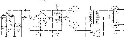 POWER CONMECTIONS A-GROUND B- 6.3V. С - aa5o-3oo v D-BIAS £-в^-г50-75o V (see FiGuRe 5 j * = fu1ArCHED PAIR OFRESlSTORS, lp S IS 6.3V. Oi С A в с D E B-t- TO FINAL Figure 4 SCHEMATIC OF BEAM POWER TUBE MODULATOR M-0 - 250 d.c. milliammeter Тг- Paiy-pedance Modulation transformer 60-watt level = Stancor A-3893, or UTC S-20 Tl-Driver transformer. Stancor A-4701, or UTC S-JO. 12S-watt level - Stancor A-3894 1 ... 61 62 63 64 65 66 67 ... 80 |
|
© 2026 AutoElektrix.ru
Частичное копирование материалов разрешено при условии активной ссылки |