 |
 |
 |
| Главная Журналы Популярное Audi - почему их так назвали? Как появилась марка Bmw? Откуда появился Lexus? Достижения и устремления Mercedes-Benz Первые модели Chevrolet Электромобиль Nissan Leaf |
Главная » Журналы » Simple coaxial reflectometer 1 ... 62 63 64 65 66 67 68 ... 80 output tubes, and a plate current milliammeter. The power supply has not been included. The 6SJ7 pentode first stage is coupled through the volume control to the grid of a 6J5 phase inverter. The output of the phase inverter is capacitively coupled to the grids of a 6SN7-GT which acts as a push-pull driver for the output tubes. Transformer coupling is used between the driver stage and the grids of the output tubes so that the output stage may be operated either as a class ABi or class AB2 amplifier. The Output Either 6L6, 6L6-G or 807 Stage tubes may be used in the out- put stage of the modulator. As a matter of fact, either 6V6-GT or 6F6-G tubes could be used in the output stage if somewhat less power output is required. The 807 tube is the transmitting-tube counterpart of the 6L6 and carries the same ratings and recommended operating conditions as the 6L6 within the ratings of the 6L6. But the 807 does have somewhat greater maximum ratings when the tube is to be used for ICAS (Intermittent Commercial and Amateur Service) operation. The 6L6 and 807 retail to the amateur for essentially the same price, although the 807 is available only from transmitting tube distributors. The 6L6-G tube retails for a somewhat lower price; hence it is expedient to purchase 6L6-G tubes if 360 to 400 volts is the maximum to be used on the output stage, or 807 tubes if up to 750 volts will be apphed. Tabulated in figure 5 are a group of recommended operating conditions for different tube types in the output stage of the modulator. In certain sets of operating conditions the tubes will be operated class ABi, that is with in-
creased plate current with signal but with no grid current. Other operating conditions specify class AB- Operation, in which the plate current increases with signal and grid current flows on signal peaks. Either type of operation is satisfactory for communication work. 30-3 General Purpose Triode Class В Modulator High level class В modulators with power output in the 125 to 500 watt level usually make use of triodes such as the 809, 811, 8005, 805, or 810 tubes with operating plate voltages between 750 and 2000. Figures 6, 7, and 8 illustrate a general purpose modulator unit designed for operation in this power range. Figure 8 gives a group of suggested operating conditions for various tubes. The size of the modulation transformer will of course be dependent upon the amount of audio power developed by the modulator. In the case Figure 6 REAR VIEW OF THE GENERAL-PURPOSE MODULATOR  6sj7 ОТО R-F 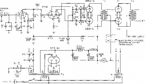 it = M/) TCHED PA IR RESISTORS, I °Ус M-0 - 500 mo. T/--Driver ttansiotmet. Sfoncor A-4761 Тг- Poiy-pedonce Modulation transformer. 300 waft rating, Stancor A-389a. 500 woff rating, Stancor A-3899. Tj-360 - 0 - 360 voits, J50 ma. Stancor PC-841Q Figure 7 SCHEMATIC OF GENERAL PURPOSE MODULATOR Ti-Suitabfe for tubes used. For 811-As = 6.3 volt, 8 amp. Stancor P-6308 for 810s - 10 volt, 10 amp. Stancor P-6461 CH,- 14 henry, 100 ma. UTC S-19. Stancor C-1001 R,- I K, 10 watts, adjustable. Set for plate current of 80 ma. (no signal) to 6B4-G tubes (approximately 875 ohms). Vi,Vt-See figure 8. of the 500 watt modulator (figures 9 and 10) the size and weight of the components require that the speech amplifier be mounted on a separate chassis. For power levels of 300 watts or less it is possible to mount the complete speech system on one chassis. Circuit Description of General Purpose Modulator FIGURE 8 suggested operating conditions for general purpose modulator
The modulator unit shown in figure 6 is complete except for the high voltage supply required by the modulator tubes. A speech amplifier suitable for operation with a crystal microphone is included on the chassis along with its own power supply. A 6SJ7 is used as a high gain preamplifier stage resistance Coupled to a 6N7 phase inverter. The audio level is controlled by a potentiometer in the input grid circuit of the 6N7 stage. Push-pull 6B4-G low fi triodes serve as the class В driver stage. The 6B4s are coupled to the grids of the modulator tubes through a conventional multi-purpose driver transformer. Cathode bias is employed on the driver stage which is capable of providing 12 watts of audio power for the grid circuit of the modulator. The modulator illustrated in figures 9 and 10 is designed for use with class В 810 triode tubes operating at a plate potential of 2500 volts. Maximum audio power available is 500 watts, sufficient to 100% modulate a transmitter running one kw. input. The modulator may be driven by the simple speech amplifier of figure 12, or by the clipper-amplifier of figure 15. Figure 9 REAR VIEW OF 810 500-WATT CLASS В MODULATOR Bios control is directly below the 810 tubes with bias supply to right. 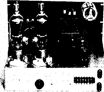 The modulator chassis includes a small low impedance bias supply capable of delivering approximately -75 volts under the changing load conditions imposed by the varying grid circuit impedance of the class В modulator. A low pass audio filter network is placed after the modulator stage to reduce harmonics generated in the audio system which would normally show up as side-band splatter on the phone signal. Frequencies above 3500 cycles are attenuated 15 decibels or more by the simple pi-network filter shown in figure 10. DRIVER TRAMSFORMER о -65 tc 75 1/- 5Y3GT 15V 4> SiB  joij fT+ io I- 400 50 W 0025 5 KV CHi 006 Сз 5 K-V KV j 006 5 ь B-l- 2500 V  Н т4 Figure 10 SCHEMATIC OF 500 WATT TRIODE MODULATOR WITH BIAS SUPPLY Tl-Driver tronsformer, 15 watts. Stancor A-4761 Тг-Modulation transformer, 500 watt. Chicago Transformer Co. CMS-3 Тз-5 volts, 3 amp. Sfoncor P-6467 Ti-Topped bias transformer, 15-100 volts. 11ГС S-51 Ts-70 volt, 70 amp. Stancor P-6461 CHi-500 ma. splatter choke Chicago Transformer Co. SR-500 CHi-7 henry, ISO mo. Stancor C-1710 M-0 - 500 d.c. milliammeter S,A-B-High voltage switch (see text) i audio osc.
г 100 < 1 к tci(5< t00< 100 1 к ; 100-; О B + 2500 v / TO OSCILLOSCOPE Figure 11 TEST SETUP FOR 500-WATT MODULATOR For c-w operation the secondary of the class В modulation transformer is shorted out and the filament and bias circuits of the modulator are disabled. Switch SiA must have 10,000 volt insulation rating. A suitable switch may be found in the war surplus ВС-ЗОбА antenna loading unit. Ail low voltage connections to the modulator are brought out to a six terminal phenolic strip on the back of the chassis. A 0-500 ma. d-c meter is placed in the filament circuit of the 810 tubes. The meter is placed across a 50 ohm, 1 watt resistor so that the filament return circuit of the modulator is not broken if the meter is removed. The modulation transformer, T2, is designed for plate-to-plate loads of either 12,000 ohms or 18.000 ohms when a 6250 ohm load is placed across the secondary terminals. The 810 tubes are correctly matched when the 18,000 ohm taps are used at a plate potential of 2500 volts, or when the 12,000 ohm taps are used at a plate potential of 2000 volts or 2250 volts. Modulator Because of the great weight of Construction the modulator components it is best to use a heavy-duty steel chassis. A 13 x 17 X 4 chassis (Bud CB-643), 14 steel panel (Bud PS-1257C) and a pair of Bud MB-449 mounting brackets make up the assembly for this particular modulator. As seen in figure 9, the CMS-3 modulation transformer is mounted in the left-front corner of the unit. The secondary terminals of T2 are to the front of the chassis, clearing the front panel by about у2 . To the right of T2 is placed the high level audio filter choke, CHi. The two 810 tubes are mounted in back of T;. To the right of the 810 tubes is the 10 volt filament transformer, T,. To the right of T.i is the 5Y3-GT bias rectifier tube. Between Ts and CHi are mounted the mica bypass capaci- tors which make up the high level filter network. Two .003 fj-id., 5000 volt mica capacitors are paralleled for Ci and also for G. G is made from a .001 jufd. capacitor and a .0015 fiid. capacitor which are connected in parallel. All of these capacitors are mounted upon a plywood bracket which insulates them from the metal chassis. This prevents insulation breakdown within the capacitors which might occur if they were fastened directly to the metal chassis. The bias supply components are mounted beneath the four-inch deep chassis. Placement of these parts is not critical. The bias adjustment control, Rl, is mounted on the back lip of the chassis as are the two high voltage terminals. Millen 37001 high voltage connectors are used for the two high voltage leads. High-voltage TV wire should be employed for all leads in the 810 plate circuit. Modulotor When the modulator has been Adjustment wired and checked, it should be tested before being used with an r-f unit. A satisfactory test set-up is shown in figure 11. A common ground lead should be run between the speech amplifier and the modulator. Six 1000 ohm 100 watt resistors should be connected in series and placed across the high voltage terminals of the modulator unit to act as an audio load. The first step is to place the 810 tubes in their sockets and turn switch Si to the phone position. The 810 filaments should light, and switch section Si.\ should remove the short across the secondary of T2. Rl should be adjusted to show ~75 volts from each 810 grid terminal to ground as measured with a high resistance voltmeter. If an oscilloscope is available, it should be coupled to point A on the load resistor (figure 11) through a 500 jufd. ceramic TV capacitor of 10,000 volts rating. The case of the oscilloscope should be grounded to the common ground point of the modulator. A plate potential of 2500 volts is now applied to the modulator, and Ri adjusted for a resting plate current of 50 milliamperes as read on the 500 milliampere meter in the cathode circuit of the modulator. Be extremely careful during these adjustments, since the plate supply of the modulator is a lethal weapon. Never touch the modulator when the plate voltage supply is on! Be sure you employ the TV blocking capacitor between the oscilloscope and the plate load resistors, as these load resistors are at high voltage potential! If a high resistance a-c voltmeter is available that has a 2000 volt scale, it should be clipped HANDBOOK 10-Watt Amplifier-Driver 655 6SJ7 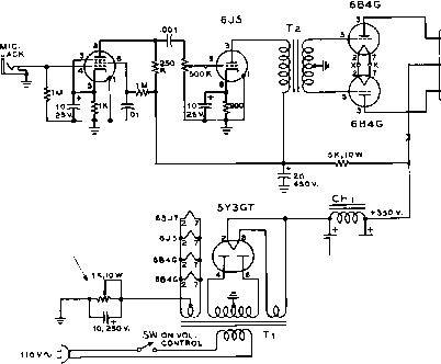 DRIVER TRANSFORMER /иС UEASURE SB4-S PLATE CURRENT HERE NOTE: ADJUST FOR PLATE CURRENT OF to MA. TO tB4-e TUBES. (APPROX. ЙЛ OHMS) ALL RESISTORS O.i WATT UNLESS OTHERWISE NOTED Tl = ЭвО-0-ЗвО VOLTS AT ISO MA. STANCOR PC-e4IO Тг-г:\ INTERSTACE TRANSFORMER STANCOR A-4zib CH 1 = 7-HENRY AT Ы0 MA. STANCOR C-I4ZI Figure 12 10-WATT SPEECH AMPLIFIER-DRIVER between the high voltage terminals of the mod-tilator, directly across the dummy load. Do not touch the meter when the high voltage supply is in operation! An audio oscillator should be connected to the audio input circuit of the exciter-transmitter and the audio excitation to the high level modulator should be increased until the a-c voltmeter across the dummy load resistor indicates an R-M-S reading that is equal to 0.7 (70%) of the plate voltage applied to the modulator. If the modulator plate voltage is 2500 volts, the a-c meter should indicate 1750 volts developed across the 6000 ohm dummy load resistor. This is equivalent to an audio output of 500 watts. With sine wave modulation at 1000 c.p.s. and no speech clipping ahead of the modulator, this voltage should be developed at a cathode meter current of about 350 ma. when the plate-to-plate modulator impedance of the modulator is 18,-000 ohms. Under these conditions, the oscilloscope may be used to observe the audio waveform of the modulator when coupled to point A through the 10,000 volt coupling capacitor. When the frequency of the audio oscillator is advanced above 3500 cycles the output level of the modulator as measured on the a-c voltmeter should drop sharply indicating that the low pass audio network is functioning properly. With speech waveforms and no clipping the modulator meter will swing to approximately 150 - 200 milliamperes under 100% modula- tion at a plate potential of 2500 volts. With speech waveforms and moderate clipping the modulator meter will swing to about 300 ma. under 100% modulation. 30-4 A TO-Watt Amplifier - Driver A simple speech amplifier-driver for a medium powered class В modulator is shown in figure 12. The amplifier is designed to work with a crystal microphone. The first stage utilizes a 6SJ7. The gain control is between the 6SJ7 plate circuit and the grid of the 6J5 second stage amplifier. The output tubes are a pair of 6B4-G low-mu tubes operating with a self-bias resistor in their common filament return circuit. Operating in this manner the 6B4s have an undistorted output of approximately 10 watts. This is sufficient power to drive most class-B modulators whose output is 500 watts or less. The driver transformer for coupling the plates of the 6B4-G tubes to the grids of the Class В stage is not shown, as it had been found more convenient to locate this transformer at the grids of the modulator tubes rather than in the speech amplifier. The correct transformer step-down ratio for driving most class В tubes has been set down in tabular form by the various transformer manufacturers. When the driver transformer is purchased one should be obtained which has the proper turns ratio for the class В tubes to be used. INTERSTAdE TRAMSFORMER U3 3TEP-UP 304TL STAfJCOP A-4ilO 6J5 Tl crystal mic, 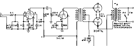 6 0 0 B+aSOV. BIAS B+ 1S00-3000V. AT 15 MA. ISee TABLED Figure 13 PUSH-PULL 304TL CLASS ABi, MODULATOR A three wire shielded cable should be used to connect the 6B4-G tubes to the driver transformer located at the grids of the class В tubes. This cable may be any reasonable length up to 25 or 30 feet. Any of the modulator configurations shown in figure 8 may be driven with this simple speech amplifier. 30-5 500-Wott 304TL Modulator Ordinarily, few amateurs would be inclined to design the high-level stages of their transmitters around type 304TL tubes. Although the 304TL unquestionably is an excellent tube, with its extremely high transconductance and power sensitivity, its price and capabilities are in excess of those required even for a kilowatt amateur transmitter. But with enormous supplies of these tubes available at a relatively low price on the surplus market it becomes economical to consider their use in high-power TABLE
X- adjust to give stated zero-signal plate current X values given for sine-wave modulation. for voice wave forus.maximum current will be approximately two-thirds sine-wave values. Figure 14 amateur transmitters. In fact, with the use of these 304TLs the cost of heating power for filaments becomes a much more significant figure than the cost of the tubes. The 304TL is ideally suited for use as a modulator for a high-power amateur transmitter. In fact, due to the relatively low amplification factor of the tube (about 12) the 304TL may even be used as a class A triode Heising modulator. Such an arrangement is practicable for modulating a medium-power transmitter when a 1500 to 2000 volt plate supply is available. The class ABi operating characteristics of the 304TL tube are shown in figure 14. An interesting fact to be observed is that under these conditions no grid driving power is required by the 304TL tubes. It is necessary only to supply the correct amount of grid driving voltage. The amounts shown may easily be obtained from a single 6J5 tube, and the usual push-pull triode driver stage for the high powered modulator may be eliminated. A suitable modulator-driver unit which will deliver 500 watts of audio from two 304TL tubes operating class ABl is shown in figure 13. The filaments of the 304TL tubes may be connected either in series or parallel for either 5 volt, 50 ampere operation, or 10 volt, 25 ampere operation. To conserve filament power during standby periods, the filaments of the 304TL tubes may be either turned off, or may be dropped to one-half voltage by means of a dropping resistor in the primary circuit of the filament transformer. This resistor may be shorted out during periods of transmission by a small relay actuated by the transmitting control system. The gain of the speech amplifier is sufficient so that an inexpensive crystal microphone may be used with the modulator. The 12ax7 6AL5 12AU7 CRYSTAL MIC. 1 6 470-1- JUJUF- /---viJUF-T- Tl - 450-0-450 VOLTS AT 105 MA-CNICASO TRANSFORMER PSR-,05 Ta-CLASS В DRIVER TRANSFORMER CHICAGO TRANSFORMER CDS-1 Тз -12.5 V. AT 15 MA. STANCOR PS-etIS LPF-2- LOW PASS FILTER UNIT CHICAGO TRANS. LPF-Z Ll- 12 H, 150 MA. CHICAGO TRANS. ffC-lilSO SR - 50 MA. REPLACEMENT TYPE SELENIUM RECTIFIER IIOV.Ij 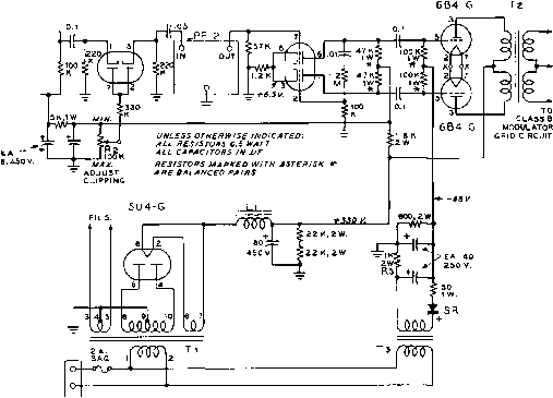 Figure 15 SCHEMATIC, 15 WATT CLIPPER-AMPLIFIER phone-c.w. switch is connected so as to short the modulation transformer and to open the filament circuit of the 304TL tubes during c-w operation. 30-6 A 15-Watt Clipper - Amplifier The near-ultimate in talk power can be obtained with low level clipping and filtering combined with high level filtering. Such a modulation system will have real punch, yet will sound well rounded and normal. The speech amplifier described in this section makes use of low level clipping and filtering and is specifically designed to drive a pair of push-pull 810 modulators such as shown in Section Three. Circuit The schematic of the speech Description amplifier-clipper is shown in figure 15. A total of six tubes, including a rectifier are employed and the unit delivers 15 watts of heavily clipped audio. A 12AX7 tube is used as a two stage microphone pre-araplifier and delivers approximately 20 volts (r.m.s.) audio signal to the 6AL5 series clipper tube. The clipping level is adjustable between 0 db and 15 db by clipping control, R;. Amplifier gain is controlled by Rl, in the grid circuit of the second section of the 12AX7. A low pass filter having a 3500 cycle cut-off follows the 6AL5 clipper stage, with an output of 5 volts peak audio signal under maximum clipping conditions. A double-triode 12AU7 cathode follower phase-inverter follows the clipper stage and delivers a 125 volt r.m.s. signal to the push-puh grids of the 6B4-G audio driver tubes. The 6B4-G tubes operate at a plate potential of 330 voks and have a 68 volt bias voltage developed by a small selenium rectifier supply applied to their grid circuit. An audio output of 1 5 watts is developed across the secondary terminals of the class В driver transformer with less than 5 per cent distortion under conditions of no clipping. A 5U4-G and a choke input filter network provide unusually good voltage regulation of the high voltage plate supply. Amplifier The clipper-amplifier may be Construction built upon the same chassis as the power supply, provided the low level stages of the amplifier are spaced away from the power transformers and filter chokes of the supply. All capacitors and resistors of the audio section should be mounted as close ro the respective sockets as is practical. For minimum hum pickup, the filament leads to the low level stages should be run in shielded braid. Those resistors in the 12AU7 phase inverter plate circuit and the grid circuit of the 6B4-G tubes should be matched to achieve best phase inverter balance. The exact value of the paired resistors is not important, but care should be taken that the values are equal. Random resistors may be matched on an ohmmeter to find two units that are alike in value. When these matched resistors are soldered in the circuit, care should be taken that the heat of the soldering iron does not cause the resistors to shift value. The resistors should be held firmly by the lead to be soldered with a long nose pliers, which will act as a heat-sink between the soldered joint and the body of the resistor. If this precaution is taken the two phase inverter outputs will be in close balance. Adjustment of When the wiring of the the Speech speech amplifier has been Amplifier completed and checked, the unit is ready to be tested. Before the tubes are plugged in the amplifier, the bias supply should be energized and the voltage across the 600 ohm bleeder resistor should be measured. It should be 68 volts. If it is not, slight changes in the value of the series resistor, R;i, should be made until the correct voltage appears across the bleeder resistor. The tubes may now be inserted in the amplifier and the positive and cathode voltages checked in accordance with the measurements given in figure 15. After the unit has been tested and is connected with the modulator, R2 should be set so that it is impossible to over-modulate the transmitter regardless of the setting of Rl. The gain control (Ri) may then be adjusted to provide the desired level of clipping consistent with the setting of R=. 30-7 A 200-Watt 811-A De-lux€ Modulator One of the most popular medium power r-f amplifier stages consists of a single tetrode tube, such as the 4-125A, 813, or 7094 operating at a plate potential of 1200 - 1700 volts and a plate current of 150 - 275 milliamperes. Such an amplifier requires a minimum of r-f driving power, allows an input of 300 to 400 watts, and yet employs power supply components that are relatively modest in cost. The 5-db signal increase between a 300 watt transmitter and a 1000 watt transmitter is very expensive when one considers the additional cost of modulator and power supply equipment. Additional economy may be achieved if the modulator and final amplifier are operated from the same power supply. The new series of Chicago-Standard plate transformers provide voltage ranges in the 1000 to 1500 volt region and are well suited for the combination of this modulator and the aforementioned r-f tubes. Within this voltage range, the 811-A triode is an excellent choice for the modulator tubes. Zero bias operation may be had up to 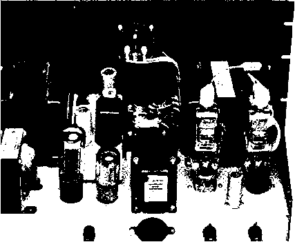 Figure 16 REAR VIEW OF 8П-А MODULATOR Modulator tubes and voltage regulator are at right with high level fitter at center of chassis. Plug-in speech amplifier is to left of clipper. Gain and clipping controls are atop the small chassis. 616/5881 is used as cathode follower driver stage for modulator. PLUG-IN SPEECH AMPLIFIER 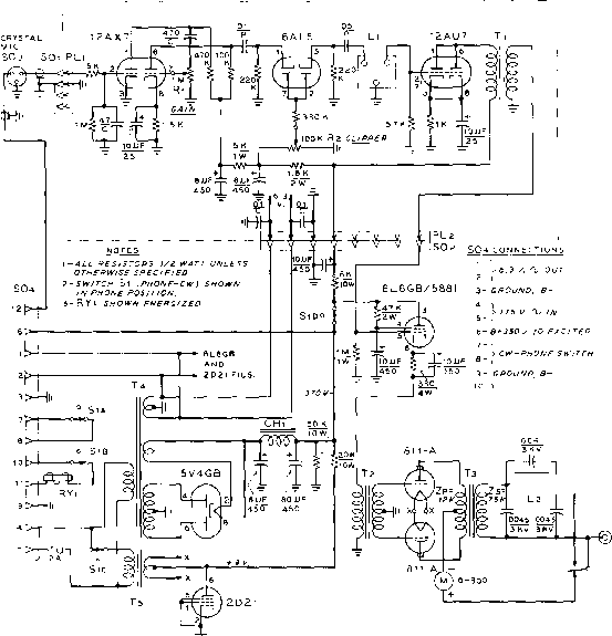 J j I ry1 CONTROL \Z-MIC. CONTROL PUSH-TO-TALK CIRCUIT ТКЛГ-?-®+Hv ourro AMPLIFIER Figure 17 SCHEMATIC, 200 WATT 811-A MODULATOR 11-1;3 /ntersfoge Transformer. Siancor A-S3 Tl- Poly-pedance class В driver transformer. 2:1 ratio. Stancor A-4761 Tl-200 watt modulation transformer. 9 К primary. SK secondary. Stancor A-3829 Ti-400 - 0 - 400 volts, 250 ma., 6.3 volts, 5 amperes. Stancor PC-8413 Ts-6.3 volts, 10 amperes. Siancor P-6308 CHt-4 fienry, 250 ma. Stancor С-Г412 Li-Low pass filter, 3000 cycle cut off. Cfi/cqgo LPF-2. L!~ Splatter filter, 300 ma. Stancor С-231Г RYi-SPOT relay, high voltage insulation, 115 valt coil. Leach #)723 with 374 coils, or equivalent 1250 volts, and only ~4.5 volts is required for 1500 volt operation. Bias voltage may be obtained from flashlight batteries or other low impedance source. Modulator The 200 watt de-luxe modulator Circuit is illustrated in figures 16 and 18 and the schematic is given in figure 17. The low level audio stages are similar to those of the speech amplifier shown in Section Six. A 12AX7 is employed as two stages of R-C amplification driving a 6AL5 speech clipper tube. A 3500 cycle low pass filter follows the clipper, removing all high order products of clipping action. A parallel-connected 12AU7 follows the filter and is transformer-coupled to a 5881 (6L6-GB) cathode follower driver stage. The impedance of the cathode circuit of the driver stage is extremely low; it provides an excellent driving source for the class В modulator grid circuit. Two 811-Л tubes are employed in the class В stage. When operated at 1000 volts, no bias supply is needed. At voltages of 1200 or above, approximately 9 volts of bias is required. This is supplied by a voltage divider composed of a 20K, 10 watt resistor and a 2D21 thyratron tube. When the miniature 2D21 is connected as a triode, it acts as a voltage regulator tube with a constant voltage drop of almost 9 volts from plate to cathode. The tube will regulate over 300 milhamperes of current while maintaining a reasonably constant voltage drop across its terminals. The center tap of the 811-A filament transformer (Ts) is thus held at a positive potential with respect to ground. Since the center tap of the 811-A driver transformer (TO is grounded, the modulator tubes are biased at a constant negative voltage equal  to the voltage drop across the 2D21 regulator tube in the cathode circuit of the class В stage. The plate to plate load impedance of the 811-A tubes when operating at 1500 volts is approximately 12,000 ohms. A multi-match type modulation transformer may be employed if desired, but in this case a Stancor A-3829 unit was used. This transformer is designed to match the plate-to-plate load impedance of 9,000 ohms to a secondary load of 5000 ohms. With the 12,000 ohm load of the 811-A tubes, a secondary load of 7,500 ohms must be used to maintain the same primary to secondary impedance ratio. This secondary load can be obtained with a single 7094 tube operating at 1500 volts and 200 milliamperes of plate current (300 watts input). Other tubes and load impedances can also be used, providing the r-f input to the modulated stage does not exceed 400 watts. For example, a 4-125A tube operating at 2000 volts and 165 rna. (330 watts) may be modulated by this audio unit. The secondary winding of the modulation transformer can pass a maximum of 300 milliamperes with safety. The audio output from the 811-A stage is passed through a high level low-pass splatter suppressor which attenuates all audio frequencies above 3500 cycles. The use of both low level and high level audio filters does much to reduce the broad sidebands and co-channel interference that seems to be so common on the amateur phone bands. A high voltage relay RYi is employed to short the secondary of the modulation transformer and remove plate potential from the modulator tubes for c-w operation. The relay is actuated by the phone-c.w. switch on the front panel of the modulator. Other segments of this switch turn off the modulator filaments and provide extra contacts to control auxiliary equipment. A 350 volt supply is incorporated in the modulator unit to power the speech amplifier and driver stage and to provide power for the r-f exciter stages of the transmitter. The various power and control leads are brought out to a multi-connector plug mounted on the rear of the modulator deck. Figure 18 UNDER-CHASSIS VIEW OF 811-A MODULATOR High Yoltage relay is between 871-A tube sockets, and low yoltage components are at apposite end of chossis. 1 ... 62 63 64 65 66 67 68 ... 80 |
|||||||||||||||||||||||||||||||||||||||||||||||||||||||||||||||||||||||||||||||||||||||||||||||||||||||||||||||||||||||||||||||||||||||||||||||||||||||||||||||||||||||||||||||||||||||||||||||||||||||||||
|
© 2026 AutoElektrix.ru
Частичное копирование материалов разрешено при условии активной ссылки |