 |
 |
 |
| Главная Журналы Популярное Audi - почему их так назвали? Как появилась марка Bmw? Откуда появился Lexus? Достижения и устремления Mercedes-Benz Первые модели Chevrolet Электромобиль Nissan Leaf |
Главная » Журналы » Simple coaxial reflectometer 1 ... 63 64 65 66 67 68 69 ... 80 HANDBOOK 811-A Modulator 661 Modulator The modulator is constructed Construction upon a steel chassis measuring 8 X 17 X 2 . A 101/2 aluminum panel is bolted to the chassis with two mounting brackets to form a rugged assembly. Placement of the major parts may be seen in figures 16 and 18. The modulation transformer Тз and the 811-A tubes occupy the right end of the chassis, balanced in weight by the power transformer T4 and modulator filament transformer Ts at the opposite end of the chassis. The center space is taken by the plug-in speech amplifier, the high level splatter fiher assembly and the 5881 driver stage. The speech amplifier is constructed as a separate unit on a small aluminum utility box measuring 5 x 3 x 2 . The bottom of the box holds two male plugs which match two receptacles mounted on the amplifier chassis. The speech amplifier, therefore, may be wired and tested as a separate unit. Clipping and audio level controls are mounted atop the amplifier box as long usage of clipper circuits has proven that these controls need not be readjusted once they are properly set. The phone-c.w. switch, relay RY-i and various small components are mounted beneath the chassis (figure 18). The input receptacle for the speech amplifier box is located adjacent to the microphone receptacle on the front panel of the modulator making the interconnecting lead less than two inches long. Also placed beneath the chassis are the filter choke for the low voltage supply and the various bypass and filter capacitors. Wiring and Testing the Modulator The speech amplifier should be wired first. The small resistors and capacitors are mounted either between the tube socket pins, or between terminals of small phenolic tie-point strips. Transformer Ti is fastened within the amplifier box and is wired in the circuit after all other wiring is completed. Plugs PLi and PL2 are mounted on the bottom portion of the box; the plug pins are wired to the proper points of the speech amplifier with short lengths of wire that allow the bottom plate to be removed for inspection and testing without the necessity of unsoldering any connections to the plugs. The modulator chassis should be wired next. All leads to Тз, RY-i, and the low pass filter should be carefully insulated from the chassis. High voltage 5000 volt test cable should be employed for these connections. The capacitors that make up the high level audio filter are mounted directly to the terminals of the filter choke which is mounted above the chassis on 1/2-inch ceramic insulators. High voltage connections to the modulator are made through Millen 37001 safety terminals. When the wiring has been completed and checked, the 12AX7, 6AL5, 12AU7, 5881, and 5V4-GB tubes should be inserted in their sockets and the speech amplifier is plugged into the modulator receptacles. The vertical amplifier of an oscilloscope should be connected to one grid terminal of the 811-A stage. Plate voltage of the 5881 should be approximately 370 volts. A low level 1000 cycle tone (approximately 0.05 volts, r.m.s.) is applied to the amplifier input. The output level of the speech amplifier is controlled by the setting of the clipping control R2 and the audio gain is controlled by potentiometer Ri in the grid circuit of the 12AX7. The cHpping control should be set so that not more than 60 volts r.m.s. is developed from one 811-A grid to ground. The modulator tubes may now be plugged in their sockets. A 7K, 200 watt resistor should be placed between the H.V. Out and H.V. In terminals, serving as a dummy load, and 1500 volts applied to the latter terminal. With no audio signal the resting plate current of the modulator stage should be approximately 15 miUiamperes, kicking up to about 160 milliamperes under full output conditions. Final adjustment of the clipping control may be made when the modulator is placed in use with the r-f section of the transmitter. Potentiometer R2 is then adjusted to limit the peak modulation level under sine wave modulation to approximately 90%. 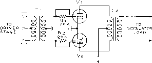 Figure 19 ZERO BIAS TETRODE MODULATOR ELIMINATES SCREEN AND BIAS SUPPLIES Low driving power and simplicity are fcey features of this novel modulator. Tubes ranging in size from 6AQ5s to 813s may be employed in this circuit. Tl-Class В driver transformer Tl-Modulation transformer Vi, Va-eAQS, 6L6, 807, 803, 813, etc. Rl, Rt-Not used with 803 and 813 803S 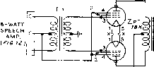 о MODULATOR О LOAD e . OPERATIMG CHAR ACTERiSTICS EG-G 1ЯМ5)= I70V0LTS DRIVING POweR= 7-S WATTS RESTING PLATE CUR.= 50 MA . MAX. PLATE IL\JH. = 310 MA. POW/ER OUTPUT= 510 WATTS SUPPRESSOR VOLT -230-340 V Ь e+2500V. Ш о 11 5 V, Figure 20 INEXPENSIVE 500 WATT MODULATOR USING 803 TUBES Т/- Po/y-pedonce Class В driver iransfarm- er 2:1 ratio. Stancor A-4761 Tl-500 wott output transformer. 18K primary, 6.2SK secondary. Chicago CMS-3 Tj-10 volts, 10 amperes. Stancor C-646J M-O - 500 ma. 30-8 Zero Bios Tetrode Modulators Class В zero bias operation of tetrode tubes is made possible by the application of the driving signal to the two grids of the tubes as shown in figure 19. Tubes such as the 6AQ5, 6L6, 807, 803, and 813 work well in this circuit and neither a screen supply nor a bias supply is required. The drive requirements are low and the tubes operate with excellent plate circuit efficiency. The series grid resistors for the small tubes are required to balance the current drawn by the two grids, but are not needed in the case of the 803 and 813 tubes. Of great interest to the amateur is the circuit of figure 20, wherein 803 tubes are used as high level modulators. These tubes will deliver 500 watts of audio in this configuration, yet they require no screen or bias supply, and can be driven by an 8 watt amplifier stage. The use of 803 tubes (in contrast to 813s) requires a higher level of driving power which is offset by the fact that these tubes can often be purchased surplus for less than four dollars. A pair of 6B4 tubes operating with cathode bias (figure 12) will suffice as a driving stage for the 803s. The power supply of the speech amplifier provides high voltage for the suppressors of the modulator stage. Shown in figure 21 is a high level modulator using 813 tubes. A full 500 watts of audio may be obtained at 2500 volts plate potential. Grid driving power is 5.5 watts. A single 807 operating as a cathode follower at 400 volts will provide sufficient drive for the modulator stage. Plate to plate load impedance for the 813s is not critical. The Chicago CMS-3 500 watt modulation transformer having a primary impedance of 18,000 ohms has been used with success, although the optimum plate load impedance of the modulator is closer to 20,000 ohms. 6C4. 6J5 ETC. DRIVER STAGE.OPERATING VOLTS, MEASURED TO GROUND.
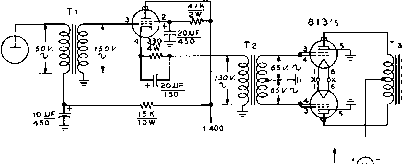 О о то о MODULATOR IO LOAD О NOTES -eXACT VALUE OF 807 CATHODE RESISTOR DEPENDS UPON RESISTANCE OF PRIMARY WINDING OF Тг, ADJUST RESISTOR FOR CATHODE BIAS OF 26. i VOLTS, PLATE CURRENT OF ВЪ-ЪЪ MA. Z-RMS OPERATING VOLTAGES AT MAXIMUM OUTPUT SHOWN ON SCHEMATIC . 6 + 2500 v, 1£Г Ш О 115 v. Tj Figure 21 500 WATT MODULATOR USING 813 TUBES Tl-7:3 interstoge transfarmer, Stancor A-S3 Tl- Poly-pedance Class В driver transfarmer. 2:1 ratio. Stancor A-4761 Ts-500 wott output frons/ormer. 18K primary, 6.25K secondary. Chicago CMS-3 T,-10 volts, 10 amperes, Stancor C-6461 M-0 - 500 mo. 350 wotts of audio are obtainable from this circuit at plate potential of 2000 volts. CHAPTER THIRTY-ONE  Despite the fact that complete transmitters may be purchased at moderate cost many amateurs still prefer to build their station equipment. The experience gained in constructing such equipment cannot be duplicated by any other means. Shown in this chapter are two complete phone and c.w. transmitters that are well suited as building projects for the advanced amateur who has had experience building other equipment. The transmitter designs are unique in that equipment of this type and power rating is not readily available on the commercial market. The first transmitter covers the 50 Mc. and 144 Mc. VHF bands and is capable of 300 watts input (phone) and 450 watts input (c.w.). The second transmitter covers the 3.5 Mc.-29.7 Mc. amateur bands and runs 375 watts input (phone) and 500 watts input (c.w.). Both transmitters are complete, including modulators and power suppHes and are system-designed for ease of operation and reliability. The cost of either unit is quite low, considering the power level involved. 31-1 A 300 Watt Phone/C-W Transmitter for 50/144 Mc. Transmitters operating in the VHF region present some specialized design problems that must be solved before reliable, efficient operation can be obtained. The first problem concerns the relative inefficiency of tuned and coupled circuits in this region. The amount of r-f power that can be lost in simple circuits is extremely high unless special pains are taken in the design and layout of the VHF stages. Radiation loss, skin effect, dielectric losses, lead inductance, distributed capacity, and parasitic ground returns all exist at the lower frequencies, but only in the higher portion of the spectrum do their effects assume such vital importance, and only at these frequencies does their cure and elimination become so essential. As a result, the necessity for close correlation between the electrical design and the mechanical properties of the VHF circuit cannot be overemphasized.  Figure 1 COMPACT 300 WATT TRANSMITTER FOR SIX AND TWO METERS IS IDEAL FOR VHF ENTHUSIAST The transmitter is built in twa sections. Upper deck contains VFO, r.f. stages and push-pull 826 amplifier. VFO tuning dial is at right, with bandswitch and meter selector switch below it. At center are the multiplier tuning controls, with buffer and final amplifier tuning controls at the left. Lower deck holds modulator and power supply. Transmitter control switches are along lower edge of the panel. The second problem concerns the vacuum tube. A combination of factors is at wotk in the common tube vihich tend to limit the efficiency of the tube as the frequency of operation is raised. Inter-electrode capacitance, lead inductance, transit time, and input circuit loading are some of the factors that cripple vacuum tube performance in the VHF region. The drop in tube operation efficiency shows up in the form of plate dissipation. Reducing the size of the vacuum tube to combat the various operational problems reduces its power handling capability, since only small element areas are then present for heat dissipation. Tetrode vs. The combination of inter-elec-Triode trode capacitance and lead in- ductance in the simple tetrode tube produce a phenomenon called self-neutralization. At some one particular frequency in or near the VHF region the tetrode tube is inherently self-neutralized due to the circuit elements within the tube structure and the external inductance of the screen-to-ground path. Below this frequency normal neutralizing procedures apply; but above this frequency special neutralizing circuits are required. These circuits are usually frequency sensitive. The self-neutralizing frequency of the less expensive screen grid tubes usually falls between 20 - 50 Mc, requiring that the tubes be re-neutralized when the frequency of operation is changed from 50 Mc. to 144 Mc, and often when the operating frequency is moved about within one of these bands. The newer external anode tetrodes are free of this problem as their self-neutralization frequency falls well above the 144 Mc. amateur band. The triode tube, on the other hand, has no frequency of self-neutralization. The maximum frequency at which neutralization is effective is dependent upon the inductance of the tube leads, the electron transit time, and the interelectrode capacitance. Rather than a point in the spectrum at which the neutralization problems abruptly change, the neutralization point of the triode tube merely grows more obscure as the operating frequency is raised, until above a certain frequency neutralization is no longer possible. Fortunately, small, compact, inexpensive triode tubes exist that are capable of efficient operation well into the VHF region, and two tubes of this general type are employed in this transmitter. Special circuits are also used to ensure that the tubes remain in neutralization over the operating range. Transmitter A block diagram of the r-f Circuitry circuitry is shown in figure 2. The transmitter is divided into two sections. The exciter section (Vi-Vi) delivers about ten watts of power over the frequency ranges of 50 - 54 Mc. and 144-148 Mc. A 5763 is employed either as a crystal controlled oscillator or as a variable frequency oscillator, operating in the 8-9 Mc. region. Two separate oscillator tuned circuits are employed as the tuning rates for the two bands are different. The 2 meter VFO covers the range of 8.0 - 8.222 Mc, and the 6 meter VFO tunes 8.333 - 9.0 Mc. The tuning capacitors of the two circuits are ganged for tuning ease. Tubes V2 and Vs multiply the overall VFO range to the 48 - 54 Mc. spectrum. At this point a simple switching system permits Va to drive either the intermediate amplifier XTAL iHOH OSC, 
(а-я МО 826 (5i>-5*wc.) 9903/5894 ® U4MC. Lii.LiE 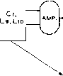 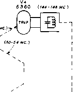 826 1 L11A If О XI 44 MC.- SHORTING BAR Vs 9903/ 5894 B-t-- (!44-f46 MC.) Ve 826 , (SOMC.) LliB ~- 144 MC. Figure 2 BLOCK DIAGRAM OF VHF TRANSMITTER A-Genera/ fronsmitter circuit, showing operating frequencies of tlie various stages. Vj is a plug-in frequency multiplier. В-Quarter-wave tank circuit is employed in amplifier plate configuration at 144 Mc. Shorting bar is removed far SO Mc, and Cs-L,i resonates at this frequency. С-Linear half-wave tank section is employed as interstage coupler at 144 Mc. Inductor Lm resonates circuit to 50 Mc. tube Vs directly for 50- 54 Mc. operation, or via a tripler stage (Vi) for 144- 148 Mc. operation. A 9903/5894 (VO is employed as the driver stage for the push-pull triode final amplifier. This driver tube operates as a straight amplifier on both bands. A unique coupling circuit, shown in figure 2C, is employed between the 9903/5894 and the push-pull 826 stage. The plates of the buffer and grids of the final stage are coupled to the ends of a loaded, half-wave 144 Mc. transmission line. The 50 Mc. coil is placed at the electrical center of the 144 Mc. line. Tuning capacitor C is tapped on the line at a point which permits each circuit to be resonated. Thus the combination LsA-B, Lio, Ci is capable of tuning the 2 meter and 6 meter ranges simultaneously, eliminating the need for plug-in coils or coil switching. Neutralization of the 9903/5894 is not required if adequate inter-stage shielding is used. The power amplifier stage employs two type 826 tubes in push-pull. These compact triode tubes are well suited to VHF work as their lead inductance is small and their inter-electrode capacitance is reasonably low. The tubes have adequate plate dissipation and a high reserve of filament emission. The amplifier has been run at one kilowatt input (2000 volts at 500 milliamperes) for c.w. operation for extended periods of time without apparent damage to the tubes, but this practice is not recommended for maximum tube life. A modified form of two band plate .circuit is employed in the amplifier stage, as shown in figure 2B. A quarter-wave 144 Mc. transmission line is employed, tuned to frequency by butter-fly capacitor Cs. The cold end of the line is shorted by a heavy strap which is removed for 50 Mc. operation. At the latter frequency, resonance is established by capacitor Ce and coil L12 which is mounted at the Le Олл-1лаНС.) то Le, {BELOUf) 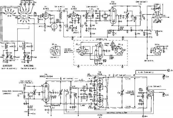 TO в.э V. I (SOUC. ANT.) NOTES: I - C= .001JJF, SOO VOLT DISC CERAMIC. 2.-ALL CAPACirOHS IN OSCILLATOR TUNED CIRCUITS ARE SILVER М/СЛ. 3-ALL RESISTORS l-WATT UNLESS OrNERWISE SPECIFIED. BIAS г (-35 V. ) (SEE Pre. e ] CiA-B-25 - 25 /iiJitd. Bud LC-1661 Ct, Ci-/5 - /5 jLiLtd. Bud LC-1660 C. Ci-8 - 8 iLiifd. Bud LC-1659 CIO- 10 iLfifd. butterfly. Johnsort 11MB11 c7-35 - 35 ллМ. Bud LC-1667 25 - 25 n/ifd. butterfly. B&W JCX-ISS, re stator remoyed in each section BIAS№1 (-eOV.) (SEE PIS. в) Figure 3 SCHEMATIC R-F SECTION OF VHF TRANSMITTER Cs-35 jii/xM., .024 spacing. Bud LC-1872 Cio-50 iiiifd., .024 spacing. Bud LC-1873 С11, С),-1 - 7 liiifd. See figure 13 RFCi-2.5 mh. National R-lOO RFCi-Ohmite Z-50 RFC,-Ohmite Z-144 5iA-B-2 deck, 3 pole, 6 position rotary ceramic switch. PLl-Octal plug, Amphenol PLr-Naval plug (9 pin) See text PLl-Octal plug, Amphenol Lt-Lu-See figure 12, coi7 table Xi.Xt-8.0 - 9.0 Ale. crystals, type f Г-243 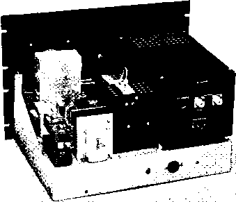 B-plus end of the transmission line. The 144 Mc. linear lines (LnA-B) serve merely as connections between the tubes and the coil at 50 Mc. An attempt was made to do away with the shorting bar, permitting the amplifier tank circuit to operate in the same manner as the buffer circuit which requires no component changes when the operating frequency is changed from band to band. It was found that the resulting drop in plate circuit efficiency was so high as to be unacceptable. Wing nuts are therefore provided to permit rapid removal of the shorting bar when 50 Mc. operation is desired. Amplifier Neutralization Circuit Because of electron transit time, and the combination of lead inductance and interelectrode capacitaiKe the us- Figure 5 CLOSE-UP OF INTERIOR OF VHF FINAL AMPLIFIER Two 826 triode tubes are used in unique puslt-pull circuit for 50 Mc. and 144 Mc. operation. Linear tanic circuit is employed for 144 Me. with removeable shorting bar in foreground. Butterfly tuning capacitor is mounted on ceramic insulators above linear tank and connected to it by means of copper straps on rear stator terminals. SO Mc. inductor is placed at cold end of 2-meter tanlc. Air is drawn into enclosure through ventilation holes drilled below 826 sockets. Note that the sockets are split to reduce possibility of flash-over. At left of enclosure are 6360 (Y-3) and sockets SO-; and SO-2 for 144 Mc. plug-in frequency multiplier. The SO Mc. adapter PL-3 is in place. Oscillator tuning slugs are seen on right side of oscillator compartment at left. 50 Mc. coil is in place atop buffer compartment. Figure 4 REAR VIEW OF VHF TRANSMITTER Finol amplifier compartment is at right with antenna receptacles and loading capacitors on rear ot enclosure. Ventilation holes are drilled above 826 tubes to aid air circulation. Entire top should be replaced with perforated material if extended periods of operation are encountered. Buffer compartment is to left of large enclosure, with 9903/5894 tube mounted in inverted position. Grid coil (Ls, see figure 7) plugs in holder at top of compartment. Grid tuning capacitor is panel driven by phenolic shaft extension. The 144 Mc. multiplier box is in position behind buffer compartment Variable frequency oscillator is at left af chassis, with plug-in crystals mounted an the side. Oscillator tube Vi can be seen in front of enclosure. Low voltage power supply components are in left corner of cliassis. ual cross-neutralization system is not effective over the range of 50 - 148 Mc. The amplifier may easily be neutralized at either end of the spectrum, but the correct capacitor settings at 50 Mc. are not the same as the settings for 144 Mc. In either case, however, one setting of the capacitors is sufficient for the stage to remain in complete neutralization across one amateur band. For a time the amplifier was re-neutralized each time the frequency of operation was shifted from band to band, but this chore was finally eliminated by the use of the neutralization system shown in the schematic of figure 3- Conventional cross-neutralization (capacitors Cn, C12) is employed at 144        Figure б UNDER-CHASSIS VIEW OF 300 WATT VHF TRANSMITTER SiMo ns-volt blower motors for 826 tubes are lit upper left corner of chassis. Buffer plate line LsA-B occupies left-hand portion of chassis. All leads are kept clear af this area. Under-chassis power leads are run in shielded braid ta reduce r-f pick-up. An L -shaped shield partition isolates frequency doubler stages from buffer plate line. Capacitors Сг and Cs are ganged, as are capacitors Сз and Ct. Power supply components occupy lower right-hand corner of chassis. The top of the 9903/-5894 buffer tube projects through hole at center of chassis. Mc, and a simple link neutralization circuit (L14-L15) is employed to complete neutralization at 50 Mc. This double neutralization circuit results in absolute stability of operation on both bands. Since the 50 Mc. plate coil L12 is decoupled from rhe 144 Mc. tank circuit by the shorting bar, very little spurious coupling exists between the two neutralizing circuits and adiustments are simple and may be made once and then forgotten. The Band-changing System A frequency shift between 50 Mc. and 144 Mc. may be made in a matter of minutes. Switch Si selects the correa crystal or VFO range. The plate coil La is broadly resonant over the 8-9 Mc. range and requires no adjustment after initial setting. The 5763 and 6360 plate circuits may be resonated to the correct frequency for either band without the necessity of coil changing. For 144 Mc. operation, however, it is necessary to remove the 50 Mc. plug, PL-3 (figure 7) and insert in its place the 144 Mc. tripler box (figure 3 ). In addition, grid coil Ь of the 9903/5894 stage must be changed. The amplifier plate circuit shorting strap is removed for 144 Mc. Finally, the buffer and amplifier plate tank circuits must be resonated to frequency. Separate antenna coupling systems are employed for each band. Two coupling loops are used, the 144 Mc. loop (Ьз) is coupled to the quarter-wave tank circuit, and the 50 Mc. loop (Lie) is coupled to plate coil L12. Power Supply The low voltage supplies are and Modulator located on the rear of the r-f deck, and are diagrammed in figure 8. A voltage doubler selenium supply provides 600 volts for the 9903/5894 stage and 270 volts for the exciter. A second selenium rectifier supply provides negative bias for the buffer and final amplifier stages. Isolating diodes De and Dt reduce interaction between the two bias voltages. The high voltage plate supply and modulator are located on a separate deck. The supply provides 1500 volts at 500 ma. for the modulator and final amplifier stage. The modulator consists of a pair of 811-A tubes, operating   Figure 7 CLOSE UP OF PLUG-IN COMPONENTS 144 Mc. plug-in tripler box containing 6360 {V-4) is at center. Tube is mounted at angle an small plate with ventilation holes drilled in box above top af tube. 9-pin plug РЦ is made from portion of a Vector socket. 50 Mc. plua PL} is at upper left, with 144 Mc. coil ts directly below it. SO Mc. coil U is at right. See figure 12 for coil data. 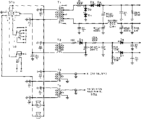 BIAS 1 -60v,) BIAS г (-35V.) (.PLACE .01 CERAMIC CAPACITOR At EACH FILAMENT PIN.)
Figure 8 SCHEMATIC, LOW VOLTAGE SUPPLIES AND METER SWITCHING CIRCUIT Tj-600/300 v., ct., 360 mo. Use 300 volt taps tor voltage doubler service. Triad P-3. Тг-125 vo/ts, 50 mo. Stancor PA-8421 T,-7.5 volts, a o. Stancor P-6I38 Tl,-6.3 volts, 6 a. Stancor P-3036 Di-i-i-i-Selenium rectifier, 700 mo., RMS input voltage: 775. Maximum peak inverse voltage: 495. Sarkes-Tarzian Model 108 D5-S-7-Selenium rectifier, 75 mo., RMS input voltage: 730, Sarfces-Torzion Model 75 Bi, Вг-Small 11S-volt blower motor. 5г-2 pole, 6 position rotary switch. SO3-8 prong octal socket (see figures 3 and 10) class B. Any one of the speech amplifiers shown in chapter 30 is suitable for use with the modulator. The complete schematic of this deck is shown in figure 10. High voltage primary circuits are energized by relay RYi after the plate circuit control switch S2 Is closed. External relay control terminals are provided for auxiliary circuits. Metering A 0-100 d.c. milliammeter (M2, Circuits figure 10) is employed to monitor the low voltage circuitry. A six position switch (S2, figure 8) places the meter across 150 ohm shunts in the plate and grid circuits as shown in the table of figure 8. Meter Ml reads plate current of the modulator and final r-f amplifier. This meter is placed in a high potential circuit, and should have a bakelite case and an insulated zero-set control. Transmitter The overall layout of the r-f Construction section can be seen in figures 4, 5, and 6. The foundation consists of a 13 X 17 x 3 aluminum chassis firmly fastened to a 1214 x 19 relay rack panel. The oscillator compartment (figure 9) measures 2 x 4 x 6 . The grid circuit compartment for the 9903/5894 is 3 x 4 x 5 in size, and the plug-in 144 Mc. tripler box measures 2 x 3 x ЗУг . The push-pull 826 final amplifier is enclosed in an aluminum box measuring 6 x 7 x 12 . This compartment is mounted clear of the chassis on Y2-inch metal posts. Care must be taken to see that each corner of the box makes a good electrical ground with the chassis. The plug-in tripler box fits into two tube sockets (SO-1 and SO-2) placed in line with the extension shaft that drives buffer grid capacitor Ce. The special sockets with 50 Mc. plug PL-3 inserted in SO-1 can be seen in figure 5. The 9903/5894 buffer socket is mounted to the top of the grid circuit compartment with the plate leads projecting out of matching holes cut in the bottom of the box and the chassis. 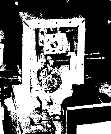 Figure 9 INTERIOR, HIGH STABILITY VFO FOR VHF TRANSMITTER Two gang ascHlaiar tuning capacitor C,A-B is panel mounted at top of enclosure. Variable trimming capacitors are at the right, with slag-tuned coils directly below. Bandswitch SiA-B Is placed at bottom af front panel, with crystal sockets at left. The twa leads ta ascillator tube socket pass through large rubber grommet mounted on chassis deck. After alignment Is completed, a drop of naif polish is placed an end of coil slag ta eliminate mechanical vibration of slug. Note that rear of case is bolted in place with eight sheet metal screws to provide rigidity ta enclosure. Oscdiatar tube socket is in foreground, partially hidden by selenium rectifier. Ventilation holes are drilled in the top of this box, and grid coil Ls mounts in banana plugs mounted on a polystyrene plate atop the box. Two 826 sockets are mounted at the front end of the amplifier box on metal spacers. Trouble occurred with the sockets flashing over on occasional modulation peaks. Accordingly, that portion of the socket holding the two plate pins was cut away and the pin connectors were bolted directly to the ends of the plate circuit straps, LuA and LuB. The back of a hacksaw blade and cutting compound are used to cut grooves across the top and bottom surfaces of the socket. A sharp blow with a hammer will fracture the socket along the groove lines. Ventilation holes are drilled in the box and chassis directly below the tubes and are covered with window screen to reduce spurious energy radiation through the openings. The two IVs wide aluminum straps that serve as the 144 Mc. tuned circuit are supported at the B-plus end on two solid ceramic insulators. Two more insulators of the same height serve to mount the butter-fly capacitor to the box. Small copper strips connea the tank straps to the stator terminals of the variable capacitor. The 50 Mc. coil and the re- 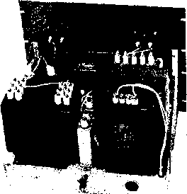 Ftgure 11 REAR VIEW POWER SUPPLY CHASSIS Power supply is built upon steel chassis. Power transformer and modulation transformer are at rear of chassis. Three 4 /ifd., 2KV filter capacitors are connected in parallel to provide adequate dynamic reserve. One capacitor is placed under the chassis. Insulated, high voltage terminal is employed for B-plus lead. Rectifiers are at right, front of chassis, with modulator tubes at left-front. 1 ... 63 64 65 66 67 68 69 ... 80 |
|||||||||||||||||||||||||||||||||||||||||||||||
|
© 2026 AutoElektrix.ru
Частичное копирование материалов разрешено при условии активной ссылки |