 |
 |
 |
| Главная Журналы Популярное Audi - почему их так назвали? Как появилась марка Bmw? Откуда появился Lexus? Достижения и устремления Mercedes-Benz Первые модели Chevrolet Электромобиль Nissan Leaf |
Главная » Журналы » Simple coaxial reflectometer 1 ... 65 66 67 68 69 70 71 ... 80 of fieavy modulation. Eight 60 fiid., 450 volt tubular electrolytic capacitors are connected in series parallel to form a 30 fiid., 1800 volt unit. A small bias supply delivering -105 volts for the 7094 amplifier and keyer is also included on the chassis. Layout and vviring of the supplies are shovvn in figures 27 and 29. The modulator has been previously shovvn in Chapter 30, figure 17. The speech amplifier supply provides 370 volts for exciter operation. One section of the phone-c.vvr. relay (RYaA) shorts out the time delay circuit on the exciter deck for phone operation, and a high voltage relay RYi is employed to remove the modulator for c.w. operation. Six volts is also supplied to the exciter for filament service. This filament circuit is balanced to ground to reduce residual hum in the speech amplifier, so the ground circuit cannot be employed as a filament return in the exciter. Exciter Tune-up and Operation Each deck of the transmitter should be tested as an individual unit before the transmitter is tested in entirety. Screen voltage of the 2E26 stage should always be set at zero by means of potentiometer Ri (figure 17) when the exciter is operated without the final amplifier, since the 2E26 plate circuit is incomplete, and excessive screen current will be drawn by the 2E26 unless the, screen potential is removed. Oscillator calibration may be adjusted by varying the spacing of the turns of coil Li, or 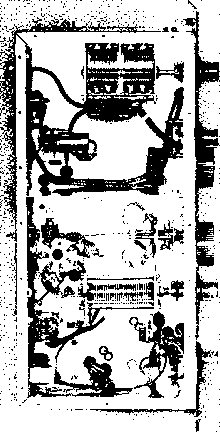 Figure 26 UNDER-CHASSIS VIEW OF POWER AMPLIFIER All power wiring beneath the chassis is placed within braid to reduce piclcup of r.f. energy. Note that shield divides area into two sections. Smaller area contains output capacitor af pi-network, 6ALS diode voltmeter and high voltage leads. Larger area contains grid circuit components and meter switch. Sensitive relay RYs is mounted to wall of the chassis behind the grid tuning capacitor. Three .001, S Kv. ceramic screen bypass capacitors are mounted close to socket terminals. Grid turret switch is driven from plate turret atop chassis. 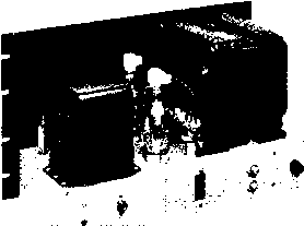 Figure 27 REAR VIEW OF POWER SUPPLY Primary power leads pass through bulkhead-type filter capacitors to prevent radiation of TVI-producing harmonics from power line. Voltage regulator tube for bias supply is visible in corner of chassis. by changing the value of the auxiliary padding capacitor C2. Alignment of the 6AC 7 and 6AG7 stages is done by observation of the grid current of the 2E26 stage, as measured across shunt resistor K4 in the grid return circuit. This circuit is not connected to the meter switch, since it requires only one preliminary reading during initial tune-up. Coil l2 is peaked at about 3.6 Mc. with padding capacitor about half meshed. If grid current to the 2E26 is excessive, the 15K resistor shunted across coil l2 may be reduced in value. Grid current should remain between 2 and 3 milliamperes across any band. After 80 meter alignment is completed, bandswitch Si is set to the 10 meter position. The slug of coil La is adjusted for maximum grid current across the 28 Mc. band. Coil Ls resonates to 14 Mc. for this operation. The bandswitch is next set to the 15 meter position and the VFO tuned to 21.2 Mc. Padding ca- вб6-А CH 1 ry4a  о о о
tL Ai 5:-i 60JUF Т Т ov. tt TF -@ B- 1S0OV. 450 EACH T -r 3SK 50 W 35K SOW -OB-  о о о £70 1N92 -рЙ-Л№ 250V. + 20 к 5 W 1 6, л и 4 \* SV v,----\4c * SWi ON-OFF / Г5 к о- 4 Г/С } О CONTROL 600 V, 650V. Figure 28 SCHEMATIC, TRANSMITTER POWER SUPPLY Cl, Ct-Bulkhead type, 0.1 tifd. 600 yolt capacitor. Sprague Hypass, or equiyalertt CHi-70 henry at 300 ma. Chicago R-103 RFC- Hash suppression choke. Millen 77866 RYi-DPDT re7oy, 20 amp. contacts, 115 y. a-c coil SOs-Fight pin receptacle, Cinch-Jones Tl-1710/1430 each side ct., 300 ma., CCS. Chicago P-1S12 Tl-2.5 y., 10 a., 10 KV insulation, Stancor P-3060 Ts-725 y., 50 ma 6,3 v., 2a. Stancor PA-S421 pacitor Cs is adjusted for correct grid current across tlie 21 Mc. band. As a last step, the bandswitch is set to 20 meters, the VFO tuned to 14.2 Mc. and capacitor Ce adjusted for uniform grid drive across the 20 meter band. The consistency of grid drive across the various amateur bands is controlled by the shunt resistors placed across coils Li and La. The lower the value of these resistors, the more uniform is the grid drive across the various bands. At the same time, the grid current of the 2E26 stage drops as these resistors are lowered in value. The values given in the schematic give good results on all bands, since the grid current of the 2E26 may vary over a 2:1 ratio across an amateur band with little change in output from the stage. Keying of the exciter is smooth and click-less. Buffer keying is controlled by the adjustment of potentiometer Ra. The buffer should turn on before the 2E26 sitage ,and remain on after the 2E26 has been cut-off. Time delay before the transmitter is turned off after keying is controlled by potentiometer Rii. Current flowing through relay coll RY2 may be varied by changing the two plate load resis- tors of the right-hand section of keyer tube Vt. The plate load resistor is made up of a 15K and a lOK resistor. The lOK resistor may be removed and a lOK relay coil may be inserted in its place if an extra relay is desired for operation of auxiliary circuits. Spring tension of relay RY2 may be varied for optimum relay operation after the circuit has been adjusted. Exciter keying should be relatively soft as the addition of the amplifier stage will sharpen it to some extent. The 0.1 /tfd. waveform-ing capacitor in the bias return lead of the 2E26 may be increased in value to soften the exciter keying to compensate for the sharpening action of the class-C amplifier following the keyed stage. In actual practice, the keying of the exciter should be adjusted so that dots run together when sent on a bug at a rate of about 25 w.p.m. The keyer may be disabled if it is desired to make adjustments to the r.f. section of the exciter. Keyer tube Vt is removed from the socket and pins 1 and 7 are grounded. Relay RY2 is then held closed by placing a piece of cardboard under the back contacts. 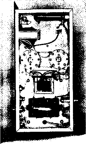 Figure 29 UNDER-CHASSIS LAYOUT OF PARTS IN POWER SUPPLY The 866-A sockets are sub-mounted on inch ceramic insulators. Eight electrolytic capacitors are mounted on phenolic plate and banded with insulated strap to form high voltage filter capacitor. Bias transformer is next to rectifier tube sockets. All high voltage connections are made with 5 KV televisian-type wire. PL7 R F, AMPLIFIER 2 3 4 5 6 7 a V V V V g g 7 P 7 V I г 3 4 5 6 EXCITER PL4 MODULATOR 3 4 5 6 7 a 9 10 1112 Д Д 4 4 Л л # !6 WIRE Л Л э POWER SUPPLY PLe 7 в 9 10 11 12 13 14 ,5 EXCITER PL5 (А) note; ALL CHASSIS OF TRANSMITTERARS BONDED rOSETHER WITH SEPARATE QROUND LEAD. 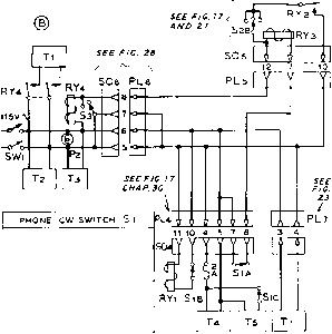 SECTION A-CONTROLS RY3 (P. A. SCREEN RELAYS ТШЕDELAY SECTION B- CONTROLS RY1 (mod. B+ shorting relay ) SECTION С - CONTROLS MODULATOR FIL. CIRCUIT SECTION CONTROLS B+ TO SPEECH AMPLIFIER Preliminary The amphfier stage may be Amplifier neutralized by supplying exci-Adjustment tation to the input circuit until rectified grid current flows. A jumper is placed across the antenna output jack j2 and plate tuning capacitor Go is resonated to frequency. Neutralizing capacitor Сэ is now adjusted until the tuning of the plate capacitor has no effect upon the reading of the rectified grid current. Preliminary tune-up into an antenna may be done with the control switch (s2, figure 17) in the stand-by position. Screen voltage is removed from the final amplifier screen circuit. Also, screen voltage cannot be applied to the tube unless relay RYs (fig. 23) is closed by applying plate voltage to the amphfier stage. Figure 30 INTERCONNECTING CABLES FOR TRANSMITTER Control Cables After testing is completed, and Power Leads the units should be placed in the racks or cabinets and control cables made up as shown in figure 30. Wire sizes should be observed, as several of the leads carry large values of filament current. In addition, a separate grounding lead should be run between the individual chassis as a safety measure. Do not depend upon a metal relay rack for a ground return. All external cables should be laced for neat appearance. A typical layout of this equipment is shown in figure 14. CHAPTER THIRTY-TWO 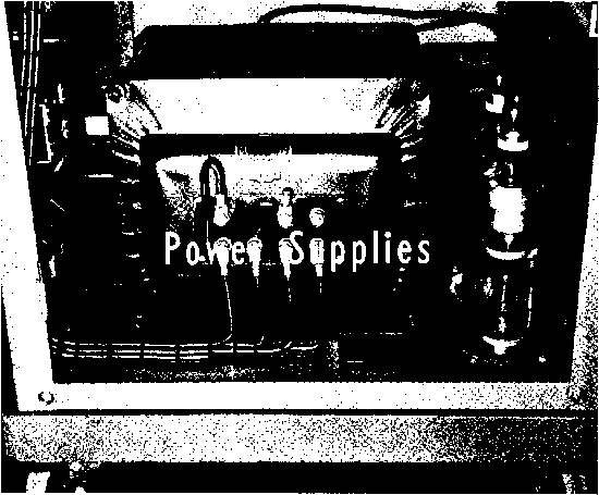 In view of the high cost of iron-core components such as go to make up the bulk of a power supply, it is well to consider carefully the design of a new or rebuilt transmitter in terms of the minimum power supply requirements which will permit the desired performance to be obtained from the transmitter. Careful evaluation of the power supply requirements of alternative transmitter arrangements will permit the selection of that transmitter arrangement which requires the minimum of power supply components, and which makes most efficient use of such power supplies as are required. 32-1 Power Supply Requirements A power supply for a transmitter or for a unit of station equipment should be designed in such a manner that it is capable of delivering the required current at a specified voltage, thar it has a degree of regulation consistent with the requirements of the application, that its ripple level at full current is sufficiently low for the load which will be fed, that its internal impedance is sufficiently low for the job, and that none of the components shall be overloaded with the type of operation contemplated. The meeting of all the requirements of the previous paragraph is not always a straightforward and simple problem. In many cases compromises will be involved, particularly when the power supply is for an amateur station and a number of components already on hand must be fitted into the plan. As much thought and planning should be devoted to the power-supply complement of an amateur station as usually is allocated to the r-f and a-f components of the station. The arrival at the design for the power supply for use in a particular application may best be accomplished through the use of a series of steps, with reference to the data in this chapter by determining the values of components to be used. The first step is to establish the operating requirements of the power supply. In general these are: 1. Output voltage required under full load. 2. Minimum, normal, and peak output current. 3. Voltage regulation required over the current range. Requirements 685 Figure 1 POWER SUPPLY CONTROL PANEL A well designed supply control panel has separate primary switches and indicator lamps for the filament and plate circuits, oyerload circuit breaker, plate voltage control switch and primary circuit fuses. 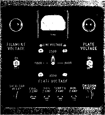 A. Ripple voltage limit. 5. Rectifier circuit to be used. The output voltage required of the power supply is more or less established by the operating conditions of the tubes which it will supply. The current rating of the supply, however, is not necessarily tied down by a particular tube combination. It is always best to design a power supply in such a manner that it will have the greatest degree of flexibility; this procedure will in many cases allow an existing power supply to be used without change as a portion of a new transmitter or other Item of station equipment. So the current rating of a new power supply should be established by taking into consideration not only the requirements of the tubes which it immediately will feed, but also with full consideration of the best matching of power supply components in the most economical current range which still will meet the requirements. It is often long-run economy, however, to allow for any likely additional equipment to be added in the near future. Current-Rating The minimum current drain Considerations which will be taken from a power supply will be, in most cases, merely the bleeder current. There are many cases where a particular power supply will always be used with a moderate or heavy load upon it, but when the supply is a portion of a transmitter it is best to consider the mini- mum drain as that of the bleeder. The minimum current drain from a power supply is of importance since it, in conjunction with the nominal voltage of the supply, determines the minimum value of inductance which the input choke must have to keep the voltage from soaring when the external load is removed. The normal current rating of a power supply usually is a round-number value chosen on the basis of the transformers and chokes on hand or available from the catalog of a reliable manufacturer. The current rating of a supply to feed a steady load such as a receiver, a speech amplifier, or a continuously-operating r-f stage should be at least equal to the steady drain of the load. However, other considerations come into play in choosing the current rating for a keyed amplifier, an amplifier of SSB signals, or a class В modulator. In the case of a supply which will feed an intermittent load such as these, the current ratings of the transformers and chokes may be less than the maximum current which will be taken; but the current ratings of the rectifier tubes to be used should be at least equal to the maximum current which will be taken. That is to say that 300-ma. transformers and chokes may be used in the supply for a modulator whose resting current is 100 ma. but whose maximum current at peak signal will rise to 500 ma. However, the rectifier tubes should be capable of handling the full 500 ma. The iron-core components of a power supply which feeds an- intermittent load may be chosen on the basis of the current as averaged over a period of several minutes, since it is heating effect of the current which is of greatest importance in establishing the ratings of such components. Since iron-core components have a relatively large amount of thermal inertia, the effect of an intermittent heavy current is offset to an extent by a key-up period or a period of low modulation in the case of a modulator. However, the current rating of a rectifier tube is estabhshed by the magnitude of the emission available from the filament of the tube; the maximum emission must not be exceeded even for a short period or the rectifier tube will be damaged. The above considerations are predicated, however, on the assumption that none of the iron-core components will become saturated due to the high intermittent current drain. If good-quality components of generous weight are chosen, saturation will not be encountered. Voltage The general subject of voltage Regulation regulation can really be divided into two sub-problems, which differ greatly in degree. The first, and more common, problem is the case of the normal power supply for a transmitter modulator, where the current drain from the supply may vary over a ratio of four or five to one. In this case we desire to keep the voitage change under this varying load to a matter of 10 or 15 per cent of the operating voltage under full load. This is a quite different problem from the design of a power supply to deliver some voltage in the vicinity of 250 volts to an oscillator which requires two or three milliamperes of plate current; but in this latter case the voltage delivered to the oscillator must be constant within a few volts with small variations in oscillator current and with large variations in the a-c line voltage which feeds the oscillator power supply. An additional voltage regulation problem, intermediate in degree between the other two, is the case where a load must be fed with 10 to 100 watts of power at a voltage below 500 volts, and still the voltage variation with changes in load and changes in a-c line voltage must be held to a few volts at the output terminals. These three problems are solved in the normal type of installation in quite different manners. The high-power case where output voltage must be held to within 10 to 15 per cent is normally solved by using the proper value of inductance for the input choke and proper value of bleeder at the output of the power supply. The calculations are simple: the inductance of the power-supply input choke at minimum current drain from the supply should be equal in henries to the load resistance on the supply (at minimum load current) divided by 1000. This value of inductance is called the critical inductance and it is the minimum value of inductance which will keep the output voltage from soaring in a choke-input power supply with minimum load upon the output. The minimum load current may be that due to the bleeder resistor alone, or it may be due to the bleeder plus the minimum drain of the modulator or amplifier to which the supply is connected. The low-voltage low-current supply, such as would be used for a v.f.o. or the high-frequency oscillator in a receiver, usually is regulated with the aid of glow-discharge gaseous-regulator tubes. These regulators are usually called VR tubes. Their use in various types of power supplies is discussed in Section 32-7. The electronically-regulated power supply, such as is used in the 10 to 100 watts power output range, also is discussed later on in this chapter and examples are given. Ripple The ripple-voltage limitation Considerations imposed upon a power supply is determined by the load which will be fed by the supply. The tolerable ripple voltage from a supply may vary from perhaps 5 per cent for a class В or class С amplifier which is to be used for a c-w stage or amplifier of an FM signal down to a few hundredths of one per cent for the plate-voltage supply to a low-level voltage amplifier in a speech amplifier. The usual value of ripple voltage which may be tolerated in the supply for the majority of stages of a phone transmitter is between 0.1 and 2.0 per cent. In general it may be stated that, with 60-cycle line voltage and a single-phase rectifier circuit, a power supply for the usual stages in the amateur transmitter will be of the choke-input type with a single pi-section filter following the input choke. A c-w amplifier or other stage which will tolerate up to 5 per cent ripple may be fed from a power supply whose filter consists merely of an adequate-size input choke and a single filter capacitor. A power supply with input choke and a single capacitor also will serve in most cases to feed a class В modulator, provided the output capacitor in the supply is sufficiently large. The output capacitor in this case must be capable of storing enough energy to supply the HANDBOOK Requirements 687 peak-current requirement of tlie class В tubes on modulation peaks. The output capacitor for such a supply normally should be between 4 /ifd. and 20 /ifd. Capacitances larger than 20 fiid. involve a high initial charging current when the supply is first turned on, so that an unusually large input choke should be used ahead of the capacitor to limit the peak-current surge through the rectifier tubes. A capacitance of less than 4 fiid. may reduce the power output capability of a class В modulator when it is passing the lower audio frequencies, and in addition may superimpose a low-frequency growl on the output signal. This growl will be apparent only when the supply is delivering a relatively high power output; it will not be present when modulation is at a low level. When a stage such as a low-level audio amplifier requires an extremely low value of ripple voltage, but when regulation is not of importance to the operation of the stage, the high degree of filtering usually is obtained through the use of a resistance-capacitance filter. This filter usually is employed in addition to the choke-capacitor filter in the power supply for the higher-level stages, but in some cases when the supply is to be used only to feed low-current stages the entire filter of the power supply will be of the resistance-capacitance type. Design data for resistance-capacitance filters is given in a following paragraph. When a low-current stage requires very low ripple in addition to excellent voltage regulation, the power supply filter often will end with one or more gaseous-type voltage-regulator tubes. These VR tubes give a high degree of filtering in addition to their voltage-regulating action, as is obvious from the fact that the tubes tend to hold the voltage drop across their elements to a very constant value regardless of the current passing through the tube. The VR tube is quite satisfactory for improving both the regulation and ripple characteristics of a supply when the current drain will not exceed 25 to 35 ma. depending upon the type of VR tube. Some types are rated at a maximum current drain of 30 ma. while others are capable of passing up to 40 ma. without damage. In any event the minimum current through the VR tube will occur when the associated circuit is taking maximum current. This minimum current requirement is 5 ma. for all types of gaseous-type voltage-regulator tubes. Other types of voltage-regulation systems, in addition to VR tubes, exhibit the added TO FULL-WAVE RECTIFIER RtPPLE IN TERMS OF С AT FULL LOAD CAPACITANCE, с ZJUF 3XIF I 4 Uf 6JUf FIGURE 2 PERCENT RIPPLE t3.l a.5 a.2 TO FULL-WAVE RECTIFIER  RIPPLE IN TERMS OF LOAD RESISTANCE LOAD, OHMS PERCENTRIPPLE 25000 (BLEEDER ONLY) 0.02 15000 10000 5000 3000 2 000 0.04 0,06 O.I 0.17 0.25 FIGURE 3 TO FULL-WAVE RECTIFIER RIPPLE IN TERMS OF Cl AND C2 AT FULL LOAD C1 C2 PERCENT RIPPLE I lOHV I L 25000 , L lOHY L г 1.2 0.7 0 25 0.06 FIGURE 4 characteristic of offering a low value of ripple across their output terminals. The electronic-type of voltage-regulated power supply is capable of delivering an extremely small value of ripple across its output terminals, even though the rectifier-filter system ahead of the regulator delivers a relatively high value of ripple, such as in the vicinity of 5 to 10 per cent. In fact, it is more or less self evident that the better the regulation of such a supply, the better will be its ripple characteristic. It must be remembered that the ripple output of a voltage-regulated power supply of any type will rise rapidly when the load upon the supply is so high that the regulator begins to lose control. This will occur in a supply of the electronic type when the voltage ahead of the series regulator tube falls below a value equal to the sum of the minimum drop across the tube at that value of current, plus the output voltage. In the case of a shunt regulator of the VR-tube type, the regulating effect will fail when the current through the VR tube falls below the usual minimum value of about 5 ma. Calculation Although figures 2, 3 and 4 of Ripple give the value of ripple voltage for several more or less standard types of filter systems, it is often of value to be able to calculate the value of ripple voltage to be expected with a particular set of filter components. Fortunately, the approximate ripple percentage for normal values TO FULL-WAVE RECTIFIER Figure 5 SAMPLE FILTER FOR CALCULATION OF RIPPLE of filter components may be calculated with the aid of rather simple formulas. In the two formulas to follow it is assumed that the line frequency is 60 cycles and that a full wave or a full-wave bridge rectifier is being used. For the case of a single-section choke-input filter as illustrated in figure 2, or for the ripple at the output of the first section of a two-section choke input filter the equation is as follows, 118 Per cent ripple =- LC-1 where LC is the product of the input choke inductance in henrys (at the operating current to be used) and the capacitance which follows this choke expressed in microfarads. In the case of a two-section filter, the per cent ripple at the output of the first section is determined by the above formula. Then this percentage is multiplied by the filter reduction factor of the following section of filter. This reduction factor is determined through the use of the following formula: LC-1 Filter reduction factor -- 1.76 Where LC again is the product of the inductance and capacitance of the filter section. The reduction factor will turn out to be a decimal value, which is then multiphed by the percentage ripple obtained from the use of the preceding formula. As an example, take the case of the filter diagrammed in figure 5. The LC product of the first section is 16. So the ripple to be expeaed at the output of the first section wiU be: 118/ (16-1) or 118/15, which gives 7.87 per cent. Then the second section, with an LC product of 48, will give a reduction factor of: 1.76/ (48-1) or 1.76/47 or 0.037. Then the ripple percentage at the output of the total filter will be: 7.87 times 0.037 or slightly greater than 0.29 per cent ripple. Resistance- In many applications where the Capacitance current drain is relatively small, Filters so that the voltage drop across the series resistors would not be excessive, a filter system made up of resistors and capacitors only may be used to advantage. In the normal case, where the reactance of the shunting capacitor is very much smaller than the resistance of the load fed by the filter system, the ripple reduction per section is equal to 1/ (27tRC). In terms of the 120-cycle ripple from a full-wave rectifier the ripple-reduction factor becomes: 1.33/RC where R is expressed in thousands of ohms and С in microfarads. For 60-cycle ripple the expression is; 2.66/RC with R and С in the same quantities as above. Filter System Many persons have noticed, Resonance particularly when using an input choke followed by a 2-fiid. first filter capacitor, that at some value of load current the power supply will begin to hum excessively and the rectifier tubes will tend to flicker or one tube will seem to take all the load while the other tube dims out. If the power supply is shut off and then again started, it may be the other tube which takes the load; or first one tube and then the other will take the load as the current drain is varied. This condition, as well as other less obvious phenomena such as a tendency for the first filter capacitor to break down regardless of its voltage rating or for rectifier tubes to have short life, results from resonance in the filter system following the high-voltage rectifier. The condition of resonance is seldom encountered in low-voltage power supplies since the capacitors used are usually high enough so that resonance does not occur. But in high-voltage power supplies, where both choke inductance and filter capacitance are more expensive, the condition of resonance happens frequently. The product of inductance and capacitance which resonates at 120 cycles is 1.77. Thus a l-fiid. capacitor and a 1.77 henry choke will resonate at 120 cycles. In almost any normal case the LC product of any section in the filter system will be somewhat greater than 1.77, so that resonance at 120 cycles will seldom take place. But the LC product for resonance at 60 cycles is about 7.1. This is a value frequently encountered in the input section of a high-voltage power supply. It occurs with a 2-fiid. capacitor and a choke which has 3.55 henrys of inductance at some current value. With a 2-fiid. filter capacitor following this choke, resonance will occur at the current value which causes the inductance of the choke to be 3.55 henrys. When this resonance does occur, one rectifier tube (assuming mercury- vapor types) will dim and tiie otlier will become much brighter. Thus we see that we must avoid the LC products of 1.77 and 7.1. With a swinging-type input choke, whose inductance varies over a 5-to-l range, we see that it is possible for resonance to occur at 60 cycles at a low value of current drain, and then for resonance to occur at 120 cycles at approximately full load on the power supply. Since the LC product must certainly be greater than 1.77 for satisfactory filtering along with peak-current limitation on the rectifier tubes, we see that with a swinging-type input choke the LC product must still be greater than 7.1 at maximum current drain from the power supply. To allow a reasonable factor of safety, it will be well to keep the LC product at maximum current drain above the value 10. From the above we see that we can just get by with a 2-/j.fd. first capacitor following the input choke when this choke is of the more-or-less standard 5-25 henry swinging variety. Some of the less expensive types of chokes swing from about 3 to 12 henrys, so we see that the first capacitor must be greater than 2 Ltfd. to avoid resonance with these chokes. A i-fitd. capacitor may be used if available, but a standard 4-jafd. unit will give a greater safety factor. 32-2 Rectification Circuits There are a large number of rectifier circuits that may be used in the power supplies for station equipment. But the simpler circuits are more satisfactory for the power levels up to the maximum permitted the radio amateur. Figure б shows the three most common circuits used in power supplies for amateur equipment. Half-Wave A half-wave rectifier, as shown in Recl-ifiers figure 6A, passes one half of the wave of each cycle of the alternating current and blocks the other half. The output current is of a pulsating nature, which can be smoothed into pure, direct current by means of filter circuits. Half-wave rectifiers produce a pulsating current which has zero output during one-half of each a-c cycle; this makes it difficult to filter the output properly into d.c. and also to secure good voltage regulation for varying loads. Full-Wave A full-wave rectifier consists of Rectifiers a pair of half-wave rectifiers working on opposite halves of the cycle, connected in such a manner that each Eox.  (a) E D.C.= 0.45Ea.C. i a.c.= I D.C. Edc. 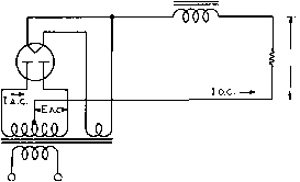 (b) Edc =0.9 Ea.c. i a.c. = 0707lD.c. 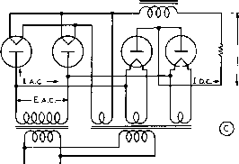 Ed.c = 0.9 Ea.c. [ a.c = i D.c. О О Figure 6 MOST COMMON RECTIFIER CIRCUITS (A) shows о holt-wove rectifier circuit, (B) is tiie standard full-wave rectifier circuit used with a dual rectifier or two rectifier tubes, and (C) is the bridge rectifier circuit. half of the rectified a-c wave is combined in the output as shown in figure 7. This pulsating unidirectional current can be filtered to any desired degree, depending upon the particular application for which the power supply is designed. A full-wave rectifier may consist of two plates and a filament, either in a single glass or metal envelope for low-voltage rectification or in the form of two separate tubes, each having a single plate and filament for high-voltage rectification. The plates are conneaed across the high-voltage a-c power transformer winding, as shown in figure 6Б. The power transformer is for the purpose of transforming the 110-vok a-c line supply to the desired second- 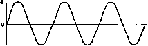 n Л A TRANSFORMER SeCONDARY VOLTAGE RECTIFIED VOLTAUE PLATE N 1 . \J \J IFIED VOLTACE PLATE N 2 COMBINED RECTIFIED VOLTACE PLATES N*H, 2 )VOLTAe£ AFTER FIRST SECTION OF FILTER D.C. VOLTACE AVAILABLE FOR RADIO USE Figure 7 FULL-WAVE RECTIFICATION Showing transformer secondary voltage, the rectified output of each tube, the combined output of the rectifier, the snioothed voltage after one section of filter, and the substantially pure d.c. output of the rectifier-filter after additional sections of filter. ary a-c voltages for filament and plate supplies. The transformer delivers alternating current to the two plates of the rectifier tube; one of these plates is positive at any instant during which the other is negative. The center point of the high-voltage transformer winding is usually grounded and is, therefore, at zero voltage, thereby constituting the negative В connection. While one plate of the rectifier tube is conducting, the other is inoperative, and vice versa. The output voltages from the rectifier tubes are connected together through the common rectifier filament circuit. Thus the plates alternately supply pulsating current to the output (load) circuit. The rectifier tube filaments or cathodes are always positive in polarity with respect to the plate transformer in this type of circuit. The output current pulsates 120 times per second for a full-wave reaifier connected to a 60-cycle a-c line supply; hence the output of the rectifier must pass through a filter to smooth the pulsations into direct current. Filters are designed to select or reject alternating currents; those most commonly used in a-c power supplies are of the low-pass type. This means that pulsating currents which have a frequency below the cutoff frequency of the filter will pass through the filter to the load. Direa current can be considered as alternating current of zero frequency; this passes through the low-pass filter. The 12P-cycle pulsations are similar to alternating current in characteristic, so that the filter must be designed to have a cutoff at a frequency lower than 120 cycles (for a 60 cycle a-c supply). Bridge The bridge rectifier (figure 6C) Rectification is a type of full-wave circuit in which four rectifier elements or tubes are operated from a single high-voltage winding on the power transformer. While twice as much output voltage can be obtained from a bridge rectifier as from a center-tapped circuit, the permissible output current is only one-half as great for a given power transformer. In the bridge circuit, four rectifiers and three filament heating transformer windings are needed, as against two rectifiers and one filament winding in the center-tapped full-wave circuit. In a bridge rectifier circuit, the inverse peak voltage impressed on any one rectifier tube is halved, which means that tubes of lower peak inverse voltage rating may be used for a given voltage output. 32-3 Standard Power Supply Circuits Choke input is shown for all three of the standard circuits of figure 6, since choke input gives the best utilization of rectifier-tube and power transformer capability, and in addition gives much better regulation. Where greater output voltage is a requirement, where the load is relatively constant so that regulation is not of great significance, and where the rectifier tubes will be operated well within their peak-current ratings, the capacitor-input type of filter may be used. The capacitor-input filter gives a no-load output voltage equal approximately to the peak voltage being applied to the rectifier tubes. At full-load, the d-c output voltage is usually slightly above one-half the secondary a-c voltage of the transformer, with the normal values of capacitance at the input to the filter. With large values of input capacitance, the output voltage will run somewhat higher than the r-m-s secondary voltage applied to the tubes, but the peak current flowing through the rectifier tubes will be many times as great as the d-c output current of the power supply. The half-wave rectifier of figure 6A is commonly used with capacitor input and resistance-capacitance filter as a high-voltage supply for a cathode-ray tube. In this case the current drain 1 ... 65 66 67 68 69 70 71 ... 80 |
|||||||||||||||
|
© 2026 AutoElektrix.ru
Частичное копирование материалов разрешено при условии активной ссылки |