 |
 |
 |
| Главная Журналы Популярное Audi - почему их так назвали? Как появилась марка Bmw? Откуда появился Lexus? Достижения и устремления Mercedes-Benz Первые модели Chevrolet Электромобиль Nissan Leaf |
Главная » Журналы » Simple coaxial reflectometer 1 ... 67 68 69 70 71 72 73 ... 80 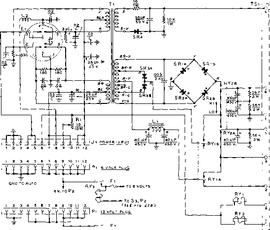 -25 V BIAS 450/300 V, TRANSMIT. + 300V TRANSMIT. + 250 V, TRANSMIT. + 250 V, R ECEIVER GND TO AUTO 12V.T0 Рг R y3 *-J-<a>- To 12 VOLTS To s3, Рг (SEE FIG. 23S) TO Sl TO s2 NOTES 1- RELAYS SHOWN IN UNENERGIZED POSITION. i.-ALL RESISTORS 7 WATT UNLESS OTHERWISE NOTED. -MOUNT AT TRANSFORMER TERMINAL. Figure 20 SCHEMATIC, 6-12 VOLT MOBILE SUPPLY Cl-Vibrator, dual interrupter, split-reed; 6 volt coils, 7I6,c.p.s. reed frequency, 7 pin base. Mallory type 7707, Oak V-6853, Radiart 5722, or G.B. A-7141 S84-Pf. Fl-30 ampere cartridge fuse. Fl-75 ampere cartridge fuse. Jl-12 pin male chassis plug. CJnch-Jones Р-3 72-ЛВ Pj-72 pin female cable socfcet. Cinch-Jones 5-ЗГ2-ССТ L,-7.5 henry, JOO ma. Siancor C-1421 1-2-7 цЬ., 1 amp. Ohmite 2-50 r-f choice RYi, RYi-D.p.d.t. relay, 6 volt coil. Advance MG/2c/6VD, Potter & Brumfield MR-11D-6V, Guardian 200-6D Coil and 200-2 assembly, or Ohmite 005Х-75вГ, or equiv. SR SRi-rwo section selenium rectifier, 150 ma., 380 volts peak inverse per section, connected for doubler service. G.B. A-7144141-P2, or two Federal 100S-A rectifiers in series for each leg (8 in all). SRs-rwo section selenium rectifier, 150 ma., 380 volts peak inverse per section, connected for center-tap service, G.E. A-7144141-P1, or two Federal 100S-A rectifiers with red terminals connected together. SRi-750 ma., 64 volt peak inverse selenium rectifier. G. C. A-7140806-P1 or Federal 1075. Tl-Vibrator-type power transformer. Dual center-tapped 6 volt primaries. Secondaries: 420 volts c.t. with 750 volt tops, 300 ma., and 20 volt, 150 ma. bias voltage winding. G.E. B-7486449-P1. TS,-8 terminal barrier strip. Cinch-Jones 8-141-Y. Note; General Electric parts may be ordered from: D. S. Clark, G.E. Ca., Product Service Renewal Parts Section of Communication Products, 509 Kent St., tltico, N.Y. Current prices plus shipping charges ore: Tj, 574.70; 55.75; SRi, SRj, SR 57.75 each; SRj, 51.40. inch thick aluminum is cut as shown in figures 21 and 22. A cut-out in one corner is necessary to clear the lower portion of the power transformer. All chassis drilhng and the cutouts for the power transformer, power input plug, and output terminal strip should be completed before the chassis is permanent- ly fastened in place with small aluminum angle brackets, two inches from the bottom of the box. One electrolytic capacitor, Ci, is mounted on an insulated plate furnished with the capacitor. When twisting the locking lugs, make sure that they do not come near the metal 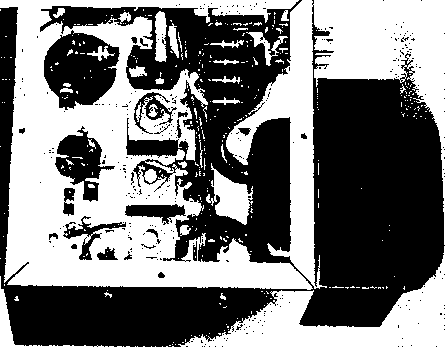 Figure 21 UNDER-CHASSIS VIEW OF POWER SUPPLY The vibrator socket is hidden by the resistors and disc ceraitiic capacitors of the hash filter. R-f choke Lt and the 25 /ltd. capacitors are above these parts on the wall of the case. Resistor Rl is nmunted to the wall, with SRi, SR;, and SRs in line below it. chassis. The can of this capacitor is more than 200 volts above ground and should be insulated with a fibre sleeve. The large seven pin socket into which the vibrator plugs should have two soldering lugs placed under each mounting bolt for the bypass capacitors which are later wired to the socket pins. If the power supply is to be mounted with the chassis in a vertical plane, pins 1 and 4 of the vibrator socket should be in a vertical plane. The smaller components below the chassis should not be installed until parts above the chassis have been assembled and wired. The transformer primary leads are wired to the input plug and vibrator socket with shortest possible leads before other parts are wired. Placement of the under-chassis parts may be seen in figure 21. Layout of the parts is not critical. Testing the After the wiring has been Supply checked, the power supply should be checked at half input voltage, but with full voltage applied to the vibrator coil. This is done by temporarily removing the jumper between pins 7 and 8 on the twelve volt power plug. Pi. Pin 8 is then Figure 22 TOP VIEW OF POWER SUPPLY INTERIOR Relays RY, and RYi are at center above chofce Li. Power transformer Ti is mounted on end of cabinet. Across top ot chassis (left to right) are vibrator and filter capacitors  FROM BATTERV I POWER RELAV AND FUSE 3 WIRE CABLE e v.- B 12 V. - * 1 г 4WIRE CABLE, TO RECEIVER г WIRE CABLE * e FOR e V. 10 FOR 12 V-
CONTROL BOX £3- SWIRE . HI-VOLTAGE i В IAS CABLE 4 WIRE HEATER i RELAY CABLE  LOW VOLTAGE INPUT PLUG J2 1 2 3 4 3 6 7 8 J3 FROM H.V. SUPPLY 12 3 4 S3 g La Sa -±r S3 - ON-OFF - .0 2 С HI-LO у лг с TRANSMIT 12 3 4 JSTO RECEIVER 6 VOLT POWER CABLE 3 4 5 6 7 12 3 4 J4 TO TRANSMITTER 12 VOLT POWER CABLE 2 3 4 5 TnRV TO HEATERS, TOKYS e VOLTS FROM Pi {FIG го) (FIG 20) TO HEATERS, 12 VOLTS FROM Pi (FIG. го) (FIG.IO) TO ry3 COI L Figure 23 CONTROL WIRING A-Block diagram ot suggested power and corttrol cables and switching system for mobile power supply, В-Schematic diagram of suggested control box including power plugs for changing heaters for 6 or 72 voJt operation. Si is tronsmit-receive switch, Si is high-low switch, and Ss is main power switch for RY,. С-6 and 72 volt power cables. jumped to pin 9- The cable is attached to Ji on the supply and to a six volt power source. Approximately half the rated voltage should be measured at the output terminal strip if the supply has been properly wired. Replace the original connections on the power plug and test the supply with full input voltage. A 2500 ohm, 100 watt resistor, or four 25 watt 115 volt lamp bulbs in series make a good load resistance. The output voltages should measure close to 450, 300, and 240 volts under load. Additional .02 jxfd. bypass capacitors at RYa, the output terminal strip, and the control box should eliminate Figure 24 CABLE HARNESS, MAIN POWER RELAY, RYs, AND REAR OF POWER CONTROL BOX ffigh voltage for the receiver, plus the control switch circuits for RYi and RYt, are brought into the control box from the power supply through is. High voltage leads for the transmitter are run directly from the supply, but the transmitter heater power and transmit-receive control circuit is run to the transmitter through control box circuit Ji, (figure 23A). any hash still present during reception. Every experienced mobileer will agree that noise in each mobile installation usually must be eliminated on a search and filter basis. Installation This power supply may be op-in the Car erated in conjunction with the suggested configuration shown in figure 2 ЗА. Note that a separate cable is recommended for the heater power circuit to reduce vibrator hash pickup, and to minimize heater voltage variations when the supply is switched from receive to transmit. Provision has been made for changing the mobile receiver and transmitter power circuits for either six or twelve volt operation as shown in the schematic of the control box in figure 23B. An eight contact plug and socket automatically make the proper connections when the six or twelve volt plug is attached. 32-6 Transistorized Power Supplies The vibrator type of mobile supply achieves an overall efficiency in the neighborhood of 70%. The vibrator may be thought of as a mechanical switch reversing the polarity of the primary source at a repetition rate of 120 transfers per second. The switch is actuated by a magnetic coil and breaker circuit requiring appreciable power which must be supplied by the primary source. One of the principal applications of the transistor is in switching circuits. The transistor may be switched from an off condition to an on condition with but the ap- 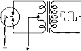 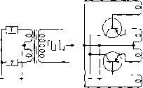 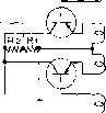 ® Figure 25 TRANSISTORS CAN REPLACE VIBRATOR IN MOBILE POWER SUPPLY SYSTEM A-Typical vibrator circuit. В-Vibrator can be represented by two single-pole single throw switches, or transistors. С-Push-pull square wave oscillator is driven by special feedback windings on power transformer. D-Addition of bias in base-emitter circuit results in oscillator capable of starting under full load. - plication of a minute exciting signal. УЪen the transistor is nonconductive it may be considered to be an open circuit. When it is in a conductive state, the internal resistance is very low. Two transistors properly connected, therefore, can replace the single pole, double throw mechanical switch representing the vibrator. The transistor switching action is many times faster than that of the mechanical vibrator and the transistor can switch an appreciable amount of power. Efficiencies in the neighborhood of 95% can be obtained with 28 volt primary-type transistor power supplies, permitting great savings in primary power over conventional vibrators and dynamotors. Transistor The transistor operation resembles Operation a magnetically coupled multi-vibrator, or an audio frequency push-pull square wave oscillator (figure 25C). A special feedback winding on the power trans- ш > 35--- P 30-- о 10 - < 0---m RiSE Time = 10i/s JJS time Figure 26 BASE-COLLECTOR WAVEFORM OF SWITCHING CIRCUIT, FOR 12 VOLT CIRCUIT Square waveshape produces almost ideal switching action. Small spike on leading edge of pulses may be reduced by proper transformer design. former provides 180 degree phase shift voltage necessary to maintain oscillation. In this application the transistors are operated as on-off switches; i.e., they are either completing the circuit or opening it. The oscillator output voltage is a square wave having a frequency that is dependent upon the driving voltage, the primary inductance of the power transformer, and upon the peak collector current drawn by the conducting transistor Changes in transformer turns, core area, core material, and feedback turns ratio have an effect on the frequency of oscillation. Frequencies in common use are in the range of 120 c.p.s. to 3,500 c.p.s. The power consumed by the transistors is relatively independent of load. Loading the oscillator causes an increase in input current that is sufficient to supply the required power to the load and the additional losses in the transformer windings. Thus, the overall efficiency actually increases with load and is greatest at the heaviest load the oscillator will supply. A result of this is that an increase in load produces very little extra heating of the transistors. This feature means that it is impossible to burn out the transistors in the event of a shorted load since the switching action merely stops. Transistor The power capability of the Power Rating transistor is limited by the amount of heat created by the current flow through the internal resistance of the transistor. When the transistor is conducting the internal resistance is extremely low and little heat is generated by current flow. Conversely, when the transistor is in a cut-off condition the internal resistance is very high and the current flow is extremely small. Thus, in both the on and off conditions 2n278 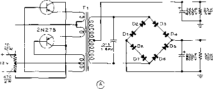 o+2S0V. AT 50 MA =1£WATTS 0 + 500 V. AT 150 MA. = 75 WATTS TOTAL POWER = 87 WATTS 2n278 OR 2n301a 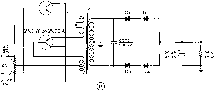 0 + 275 V. AT1£5MA=35 WATTS Figure 27 PRACTICAL TRANSISTOR POWER SUPPLIES tl-Chicago 0СГ-2 transistor transformer гг-ChJcasfo DCT-1 transistor transformer Di-Di-Sarles-Tarzian M-SOO silicon rectifier or equivalent. the transistor dissipates a minimum of power. The important portion of the operating cycle is that portion when the actual switching from one transistor to the other occurs, as this is the time during which the transistor may be passing through the region of high dissipation. The greater the rate of switching, in general, the faster will be the rise time of the square wave (figure 26) and the lower will be the internal losses of the transistor. The average transistor can switch about eight times the power rating of class A operation of the unit. Two switching transistors having 5 watt class A power output rating can therefore switch 80 watts of power when working at optimum switching frequency. Self-Starting The transistor supply shown in Oscillators figure 25C is impractical because oscillations will not start under load. Base current of the proper polarity has to be momentarily introduced into the base-emitter circuit before oscillation will start and sustain itself. The addition of a bias resistor (figure 25D) to the circuit results in an oscillator that is capable of starting under full load. Ri is usually of the order of 10-50 ohms while R2 is adjusted so that approximately 100 milliamperes flows through the circuit. The current drawn from the battery by this network flows through Rs and then divides between Ri and the input resistances of the two transistors. The current flowing in the emitter-base circuit depends upon the value of input resistance. The induced voltage across the feedback winding of the transformer is a square wave of such polarity that it forward-biases the emitter-base diode of the transistor that is starting to conduct collector current, and reverse-biases the other transistoir. The forward-biased transistor will have a very low input impedance, while the input impedance of the reversed-biased transistor will be quite high. Thus, most of the starting current drained from the primary power source will flow in Rl and the base-emitter circuit of the forward-biased transistor and very little in the other transistor. It can be seen that Ri must not be too low in comparison to the input re- 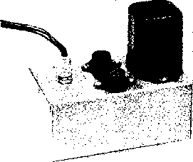 Figure 28 35 WATT TRANSISTOR POWER SUPPLY Two 2N301A power transistors ate used in this midget supply. Transistors are mounted on sanded portion ot chassis deck which acts as heat sink. See text for details. sistance of the conducting transistor, or else it will shunt too much current from the transistor. When switching takes place, the transformer polarities reverse and the additional current now flows in the base-emitter circuit of the other transistor. The Power The power transformer in a Transformer transistor-type supply is designed to reach a state of maximum flux density (saturation) at the point of maximum transistor conductance. When this state is reached the flux density drops to zero and reduces the feedback voltage developed in the base winding to zero. The flux then reverses because there is no conducting transistor to sustain the magnetizing current. This change of flux induces a voltage of the opposite polarity in the transformer. This voltage turns the first transistor off and holds the second transistor on. The transistor instantly reaches a state of maximum conduction, producing a state of saturation in the transformer. This action repeats itself at a very fast rate. Switching time is of the order of 5 to 10 microseconds, and saturation time is perhaps 200 to 2,000 microseconds. The collector waveform of a typical transistor supply is shown in figure 26. The rise time of the wave is about 5 microseconds, and the saturation time is 500 microseconds. The small spike at the leading edge of the pulse has an amplitude of about 2V2 volts and is a product of switching transients caused by the primary leakage reactance of the transformer. Proper transformer design can reduce this spike to a minimum value. An excessively large spike can puncture the transistor junction and ruin the unit. 32-7 Two Transist-orized Mobile Supplies The new Chicago-Standard Transformer Co. series of power transformers designed to work in transistor-type power supplies permits the amateur and experimenter to construct efficient mobile power supplies at a fraction of their former price. Described in this section are two power supplies designed around these efficient transformers. The smaller supply delivers 35 watts (275 volts at 125 milliamperes) and the larger supply delivers 85 watts (500 volts at 125 milliamperes and 250 volts Figure 29 SCHEMATIC, TRANSISTOR POWER SUPPLY FOR 12 VOLT AUTOMOTIVE SYSTEM Г,-Tfonsistor power transformer. 72 volt primary, to provide 275 volts at 125 ma. Chicago Standard DCT-1. Di-Di-Sarkes-Tarxian silicon rectifier, type M-500, or equivalent. sov. 2N301 A 2w ар -iW- 2N301A о о
20JJF -О-Н 27S V. gSKf AT 125 MA, 1 -o- 6- 12V. BATTERY +6 HANDBOOK Components 707 at 50 milliamperes, simultaneously). Both power units operate from a 12 volt primary source. The 35 Watt The 35 watt power unit uses Supply two inexpensive RCA 2N301A P-N-P-type power transistors for the switching elements and four silicon diodes for the high voltage rectifiers. The complete schematic is shown in figure 29. Because of the relatively high switching frequency only a single 20 /nfd. filter capacitor is required to provide pure d.c. Regulation of the supply is remarkably good. No load voltage is 310 volts, dropping to 275 volts at maximum current drain of 125 milliamperes. The complete power package is built upon an aluminum chassis-box measuring 5V4 x 3 x2 . Paint is removed from the center portion of the box to form a simple heat sink for the transistors. The box therefore conducts heat away from the collector elements of the transistors. The collector of the transistor is the metal case terminal and in this circuit is returned to the negative terminal of the primary supply. If the negative of the automobile battery is grounded to the frame of the car the case of the transistor may be directly grounded to the unpainted area of the chassis. If the positive terminal of the car battery is grounded it is necessary to electrically insulate the transistor from the aluminum chassis, yet at the same time permit a low thermal barrier to exist between the transistor case and the power supply chassis. A simple method of accomplishing this is to insert a thin mica sheet between the transistor and the chassis. Two Mil (0.002 ) mica washers for transistors are available at many large radio supply houses. The mica is placed between the transistor and the chassis deck, and fibre washers are placed under the retaining nuts holding the transistor in place. When the transistors are mounted in place, measure the collector to ground resistance with an ohmmeter. It should be 100 megohms or higher in dry air. After the mounting is completed, spray the transistor and the bare chassis section with plastic Krylon to retard oxidation.. Several manufacturers produce anodized aluminum washers that serve as mounting insulators. These may be used in place of the mica washers, if desired. The under-chassis wiring of the supply may be seen in figure 30. The 85 Wott Figure 31 shows the schematic Supply of a dual voltage transistorized mobile power supply. A bridge   Figure 30 UNDER-CHASSIS LAYOUT OF PARTS Two ?0 titd. capacitors are connected in parailel for 20 tifd. output filter capacitor. Silicon rectifiers are mounted in dual fuse clips at end of chassis. Transistors are insulated from chassis with thin mico sheets and fibre washers if suppl)r is used with positive-grounded primary system. rectifier permits the choice of either 250 volts or 500 volts, or a combination of both at a total current drain that limits the secondary power to 85 watts. Thus, 500 volts at 170 milliamperes may be drawn, with correspondingly less current as additional power is drawn from the 250 volt tap. The supply is built upon an aluminum box-chassis measuring 7 x5 x3 , the layout closely following that of the 35 watt supply. Delco 2N278 P-N-P-type transistors are used as the switching elements and eight silicon diodes form the high voltage bridge rectifier. The transistors are affixed to the chassis in the same manner as the 2N301A mounting described previously. 32-8 Power Supply Components The usual components which make up a power supply, in addition to rectifiers which have already been discussed, are filter capacitors, bleeder resistors, transformers, and chokes. These components normally will be purchased especially for the intended application, taking into consideration the factors discussed earher in this chapter. Filter Copocitors There are two types of filter capacitors: (1) paper dielectric type, (2) electrolytic type. Paper capacitors consist of two strips of metal foil separated by several layers of special 2N278 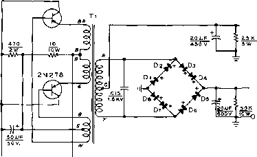 0+250 V, o+SOOV. Figure 31 SCHEMATIC, 85 WATT TRANSISTOR POWER SUPPLY FOR 12 VOLT AUTOMOTIVE SYSTEM Ti-Transistor power transformer. 12 volt primary to provide 275 volts at 125 ma. Chicago Standard DCT-2. Di-Di-Sarlces-Tarzian silicon rectifier, type M-SOO 6- 12 V. BATTERY +0 paper. Some types of paper capacitors are wax-impregnated, but the better ones, especially the high-voltage types, are oil-impregnated and oil-filled. Some capacitors are rated both for flash test and normal operating voltages; the latter is the important rating and is the maximum voltage which the capacitor should be required to withstand in service. The capacitor across the rectifier circuit in a capaciror-input filter should have a ivo -king voltage rating equal at least to 1.41 times the r-m-s voltage output of the rectifier. The remaining capacitors may be rated more nearly in accordance with the d-c voltage. The electrolytic capacitor consists of two aluminum electrodes in contact with a conducting paste or liquid which acts as an electrolyte. A very thin film of oxide is formed on the surface of one electrode, called the anode. This film of oxide acts as the dielectric. The electrolytic capacitor must be correctly connected in the circuit so that the anode always is at a positive potential with respect to the electrolyte, the latter actually serving as the other electrode (plate) of the capacitor. A reversal of the polarity for any length of time will ruin the capacitor. The dry type of electrolytic capacitor uses an electrolyte in the form of paste. The dielectric in electrolytic capacitors is not perfect; these capacitors have a much higher direct current leakage than the paper type. The high capacitance of electrolytic capacitors results from the thinness of the film which is formed on the plates. The maximum voltage that can be safely impressed across the average electrolytic filter capacitor is between 450 and 600 volts; the working voltage is usually rated at 450. When electrolytic ca- pacitors are used in filter circuits of high-voltage supplies, the capacitors should be connected in series. The positive termmal of one capacitor must connect to the negative terminal of the other, in the same manner as dry batteries are connected in series. It is not necessary to connect shunt resistors across each electrolytic capacitor section as it is with paper capacitors connected in series, because electrolytic capacitors have fairly low internal d-c resistance as compared to paper capacitors. Also, if there is any variation in resistance, it is that electrolytic unit in the poorest condition which will have the highest leakage current, and therefore the voltage across this capacitor will be lower than that across one of the series connected units in better condition and having higher internal resistance. Thus we see that equalizing resistors are not only unnecessary across series-connected electrolytic capacitors but are actually undesirable. This assumes, of course, similar capacitors by the same manufacturer and of the same capacitance and voltage rating. It is net advisable to connect in series electrolytic capacitors of different make or ratings. There is very little economy in using electrolytic capacitors in series in circuits where more than two of these capacitors would be required to prevent voltage breakdown. Electrolytic capacitors can be greatly reduced in size by the use of etched aluminum foil for the anode. This greatly increases the surface area, and the dielectric film covering it, but raises the power factor slightly. For this reason, ultra-midget electrolytic capacitors ordinarily should not be used at full rated d-c voltage when a high a-c component is present. such as would be the case for the input capacitor in a capacitor-input filter. Bleeder A heavy duty resistor should be Resst-ors connected across the output of a filter in order to draw some load current at all time. This resistor avoids soaring of the voltage at no load when swinging choke input is used, and also provides a means for discharging the filter capacitors when no external vacuum-tube circuit load is connected to the filter. This bleeder resistor should normally draw approximately 10 per cent of the full load current. The power dissipated in the bleeder resistor can be calculated by dividing the square of the d-c voltage by the resistance. This power is dissipated in the form of heat, and, if the resistor is not In a well-ventilated position, the wattage rating should be higher than the actual wattage being dissipated. High-voltage, high-capacitance filter capacitors can hold a dangerous charge if not bled off, and wire-wound resistors occasionally open up without warning. Hence it Is wise to place carbon resistors in series across the regular wire-wound bleeder. When purchasing a bleeder resistor, be sure that the resistor will stand not only the required wattage, but also the voltage. Some resistors have a voltage limitation which makes it impossible to force sufficient current through them to result in rated wattage dissipation. This type of resistor usually Is provided with slider taps, and is designed for voltage divider service. An untapped, non-adjustable resistor is preferable as a high voltage bleeder, and is less expensive. Several small resistors may be connected in series, if desired, to obtain the required wattage and voltage rating. Transformers Power transformers and filament transformers normally will give no trouble over a period of many years If purchased from a reputable manufacturer, and if given a reasonable amount of care. Transformers must be kept dry; even a small amount of moisture in a high-voltage unit will cause quick failure. A transformer which is operated continuously, within its ratings, seldom will give trouble from moisture, since an economically designed transformer operates at a moderate temperature rise above the temperature of the surrounding air. But an unsealed transformer which is Inactive for an appreciable period of time in a highly humid location can absorb enough moisture to cause early failure. Filter Choke Filter inductors consist of a Coils coil of wire wound on a lami- nated iron core. The size of wire is determined by the amount of direa current which is to flow through the choke coil. This direct current magnetizes the core and reduces the inductance of the choke coil; therefore, filter choke coils of the smoothing *vpe are built with an air gap of a small fraction of an inch in the iron core, for the purpose of preventing saturation when maximum d.c. flows through the coil winding. The air gap is usually in the form of a piece of fiber inserted between the ends of the laminations. The air gap reduces the initial inductance of the choke coil, but keeps it at a higher value under maximum load conditions. The coil must have a great many more turns for the same initial Inductance when an air gap Is used. The d-c resistance of any filter choke should be as low as practicable for a specified value of inductance. Smaller filter chokes, such as those used in radio receivers, usually have an inductance of from 6 to 15 henrys, and a d-c resistance of from 200 to 400 ohms. A high d-c resistance will reduce the output voltage, due to the voltage drop across each choke coil. Large filter choke coils for radio transmitters and Class Б amplifiers usually have less than 100 ohms d-c resistance. 32-9 Special Power Supplies A complete transmitter usually includes one or more power supplies such as grid-bias packs, voltage-regulated supplies, or transformerless supplies having some special characteristic. Regulated Where it is desired In a circuit Supplies- to stabilize the voltage supply V-R Tubes to a load requiring not more than perhaps 20 to 25 ma., the glow-discharge type of voltage-regulator tube can be used to great advantage. Examples of such circuits are the local oscillator circuit in a receiver, the tuned oscillator in a v-f-o-, the oscillator In a frequency meter, or the bridge circuit in a vacuum-tube voltmeter. A number of tubes are available for this application including the OA3/VR75, OB3/VR90, OC3/VR105, OD3/VR150, and the OA2 and OB2 miniature types. These tubes stabilize the voltage across their terminals to 75, 90, 105, or 150 volts. The rainature types OA2 stabilize to 150 volts and OB2 to 108 volts. The types OA2, OB2 and OB3/VR90 have a maximum current rating of 30 ma. and the other three types have a maximum current rating of 40 ma. The minimum current required by all six types to sustain a constant discharge is 5 ma. A VR tube (common term applied to all glow-discharge voltage regulator tubes) may be used to stabilize the voltage across a variable load or the voltage across a constant load fed from a varying voltage. Two or more VR tubes may be connected in series to provide exactly 180, 210, 255 volts or other combinations of the voltage ratings of the tubes. It is not recommended, however, that VR tubes be connected in parallel since both the striking and the regulated voltage of the paralleled tubes normally will be sufficiently different so that only one of the tubes will light. The remarks followirig apply generally to all the VR types although some examples apply specifically to the OD3/VR150 type. A device requiring say, only 50 volts can be stabilized against supply voltage variations by means of a VR-105 simply by putting a suitable resistor in series with the regulated voltage and the load, dropping the voltage from 105 to 50 volts. However, it should be borne in mind that under these conditions the device will not be regulated for varying load; in other words, if the load resistance varies, the voltage across the load will vary, even though the regulated voltage remains at 105 volts. To maintain constant voltage across a varying load resistance there must be no series resistance between the regulator tube and the load. This means that the device must be operated exactly at one of the voltages obtainable by seriesing two or more similar or different VR tubes. A VR-150 may be considered as a stubborn variable resistor having a range of from 30,000 to 5000 ohms and so intent upon maintaining a fixed voltage of 150 volts across its terminals that when connected across a voltage source having very poor regulation it will instantly vary Its own resistance within the limits of 5000 and 30,000 ohms in an attempt to maintain the same 150 volt drop across its terminals when the supply voltage is varied. The theory upon which a VR tube operates is covered in an earlier chapter. It is paradoxical that in order to do a good job of regulating, the regulator tube must be fed from a voltage source having poor regulation (high series resistance). The reason for this presently will become apparent. If a high resistance is connected across the VR tube, it will not impair its ability to maintain a fixed voltage drop. However, if the load is made too low, a variable 5000 to 30,000 ohm shunt resistance (the VR-150) will not exert sufficient effect upon the resulting resistance to provide constant voltage except over a very limited change in supply voltage or load resistance. The tube will supply maximum regulation, or regulate the largest load, when the source of supply voltage has high internal cr high series resistance, because a variation in the effective internal resistance of the VR tube will then have more control-hng effect upon the load shunted across it. In order to provide greatest range of regulation, a VR tube (or two in series) should be used with a series resistor (to effect a poorly regulated voltage source) of such a value that it will permit the VR tube to draw from 8 to 20 ma. under normal or average conditions of supply voltage and load impedance. For maximum control range, the series resistance should be not less than approximately 20,000 ohms, which will necessitate a source of voltage considerably in excess of 150 volts. However, where the supply voltage is limited, good control over a limited range can be obtained with as litde as 3000 ohms series resistance. If it takes less than 3000 ohms series resistance to make the VR tube draw 15 to 20 ma. when the VR tube is connected to the load, then the supply voltage is not high enough for proper operation. Should the current through a VR-150, VR-105, or VR-75 be allowed to exceed 40 ma., the life of the tube will be shortened. If the current falls below 5 ma., operation will become unstable. Therefore, the tube must operate within this range, and within the two extremes will maintain the voltage within 1.5 per cent. It takes a voltage excess of at least 10 to 15 per cent to start a VR type regulator; and to insure positive starting each time the voltage supply should preferably exceed the regulated output voltage rating about 20 per cent or more. This usually is automatically taken care of by the fact that if sufficient series resistance for good regulation is employed, the voltage Impressed across the VR tube before the VR tube ionizes and starts passing current is quite a bit higher than the starting voltage of the tube. When a VR tube is to be used to regulate the voltage applied to a circuit drawing less than 15 ma. normal or average current, the simplest method of adjusting the series resist- 1 ... 67 68 69 70 71 72 73 ... 80 |
||||||||||||||||||||
|
© 2026 AutoElektrix.ru
Частичное копирование материалов разрешено при условии активной ссылки |