 |
 |
 |
| Главная Журналы Популярное Audi - почему их так назвали? Как появилась марка Bmw? Откуда появился Lexus? Достижения и устремления Mercedes-Benz Первые модели Chevrolet Электромобиль Nissan Leaf |
Главная » Журналы » Simple coaxial reflectometer 1 ... 68 69 70 71 72 73 74 ... 80 Rs, series resistor -W,- dc. supply voltage  load Figure 32 STANDARD VR-TUBE REGULATOR CIRCUIT The YR-tube regulator will maintain the voltage across its terminals constant within a few volts for moderate variations in R or Cg. See text for discussion of the use of VR tubes in various circuit applications. ance is to remove the load and vary the series resistor until the VR tube draws about 30 ma. Then connect the load, and that is all there is to it. This method is particularly recommended when the load is a heater type vacuum tube, which may not draw current for several seconds after the power supply is turned on. Under these conditions, the current through the VR tube will never exceed 40 ma. even when it is running unloaded (while the heater tube is warming up and the power supply rectifier has already reached operating temperature). Figure 32 illustrates the standard glow discharge regulator tube circuit. The tube will maintain the voltage across Rl constant to within 1 or 2 volts for moderate variations in Rl or Es. Voltage Regulated When it is desired to sta-Power Supplies bihze the potential across a circuit drawing more than a few milliamperes it is advisable to use a voltage-regulated power supply of the type illustrated in figure 33 rather than glow discharge tubes. A 6AS7-G is employed as the series control element, and type 816 mercury vapor rectifiers are used in the power supply section. The 6AS7-G acts as a variable series resistance which is controlled by a separate regulator tube much in the manner of a-v-c circuits or inverse feedback as used in receivers and a-f amplifiers. A 6SH7 controls the operating bias on the 6AS7-G, and therefore controls the internal resistance of the 6AS7-G. This, in turn, controls the output voltage of the supply, which controls the plate current of the 6SH7, thus completing the cycle of regulation. It is apparent that under these conditions any change in the output voltage will tend to resist Itself, much as the a-v-c system of a receiver resists any change in signal strength delivered to the detector. Because it is necessary that there always be a moderate voltage drop through the 6AS7-G in order for it to have proper control, the rest of the power supply is designed to deliver as much output voltage as possible. This calls for a low resistance full-wave rectifier, a high capacitance output capacitor in the filter system and a low resistance choke. Reference voltage in the power supply is obtained from a VR-150 gaseous regulator. Note that the 6.3-volt heater winding for the 6SH7 and the 6AS7-G tubes is operated at a potential of plus 150 volts by conneaing the winding to the plate of the VR-150. This procedure causes the heater-cathode voltage of the 6SH7 to be zero, and permits an output voltage of up to 450 since the 300-volt heater-to-cathode rating of the 6AS7-G is not exceeded with an output voltage of 450 from the power supply. The 6SH7 tube was used in place of the more standard 6SJ7 after it was found that the regulation of the power supply could be improved by a factor of two with the 6SH7 in place of the 6SJ7. The original version of the power supply used a 5R4-GY rectifier tube in place of the 8l6s which now are used. The excessive drop of the 5R4-GY resulted in loss of control by the regulator por- 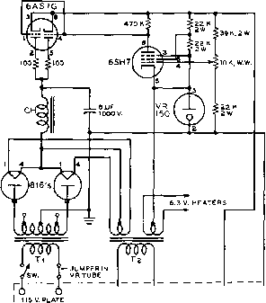 o о П5 V FILS. 0 u~i + 325 TO GND.l 450 V, Figure 33 SCHEMATIC OF VOLTAGE REGULATED POWER SUPPLY Tl-615 or 520 volfs each side of c.t., 300 ma. Stancor P-S04I. Tl-5 volts at 3 amp., 6.3 volts at 6 amp. Stancor P-5009. CH-4 henry at 250 ma. Stancor C-1412. 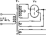
Figure 34 DESIGN CHART FOR CHOKE-INPUT POWER SUPPLIES tion with an output voltage of about 390 with a 225-ma. drain. Satisfactory regulation can be obtained, however, at up to 450 volts if the maximum current drain is limited to 150 ma. when using a 5R4-GY rectifier. If the power transformer is used with the taps giving 520 volts each side of center, and if the maximum drain is limited to 225 ma., a type 83 rectifier may be used as the power supply rectifier. The 6l5-volt taps on the power transformer deliver a voltage in excess of the maximum ratings of the 83 tube. With the 83 in the power supply, excellent regulation may be obtained with up to about 420 volts output if the output current is limited to 225 ma. But with the 816s as rectifiers the full capabilities of all the components in the power supply may be utilized. If the power supply is to be used with an output voltage of 400 to 450 volts, the full 615 volts each side of center should be applied to the 8l6s. However, the maximum plate dissipation rating of the 6AS7-G will be exceeded, due to the voltage drop across the tube, if the full current rating of 250 ma. is used with an output voltage below 400 volts. If the power supply is to be used with full output current at voltages below 400 volts the 520-volt taps on the plate transformer should be connected to the 8l6s. Some variation in the output range of the power supply may be obtained by varying the values of the resistors and the potentiometer across the output. However, be sure that the total plate dissipation rating of 26 watts on the 6AS7-G series regulator is not exceeded at maximum current output from the supply. The total dissipation in the 6AS7-G is equal to the current through it (output current plus the current passing through the two bleeder strings) multiplied by the drop through the tube (voltage across the filter capacitor minus the output voltage of the supply). 32-10 Power Supply Design Power supplies may either be of the choke input type illustrated in figure 34, or the capacitor input type, illustrated in figure 35. Capacitor input filter systems are characterized by a d-c supply output voltage that runs from 0.9 to about 1.3 times the r.m.s. voltage of one-half of the bigh voltage secondary winding of the transformer. The approximate regulation of a capacitor input filter system is shown in figure 36. Capacitor input filter systems are not recommended for use with I 15 V. о e.3V.
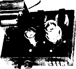
Figure 35 DESIGN CHART FOR CAPACITOR-INPUT POWER SUPPLIES mercury vapor rectifier tubes, as the peak rectifier current may run as high as five or six times the d-c load current of the power supply. It is possible, however, to employ type 872-A mercury vapor rectifier tubes in capacitor input circuits wherein the load cut-rent is less than 600 miUiamperes or so, and where a low resistance bleeder is used to hold the minimum current drain of the supply to a value greater than 50 milliamperes or so. Under these conditions the peak plate current of the 872-A mercury vapor tubes will not be exceeded if the input filter capacitor is 4 ju,fd. or less. Choke input filter systems are characterized by lower peak load currents (1.1 to 1.3 times the average load current) than the capacitor input filter, and by better voltage regulation. Design Charts for capacitor and choke input filter supplies for various voltages and load currents are shown in figures 34, 35, and 37. The construction of power supplies for transmitters, receivers and accessory equipment is a relatively simple matter electrically since lead lengths and placement of parts are of minor importance and since the circuits themselves are quite simple. Under-chassis wiring of a heavy-duty supply is shown in figure 38. Bridge Supplies Some practical variations of the common bridge rectifier circuit of figure б are illustrated in figures 39 and 40. In many instances a transmitter or modulator requires two different supply voltages, differing by a ratio of about 2:1. A simple bridge supply such as shown in figure 39 will provide both of these voltages from a simple broadcast replacement-type power transformer. The first supply of figure 39 is ample to power a transmitter of the 6CL6-807 type to an input of 60 watts. The second supply will run a transmitter running up to 120 watts, such as one employing a pair of 6146 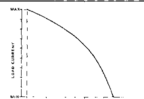 0.9 1.0 1.1 1.2 1.3 1.4 RATIO OF DC. OUTPUT VOLTAGE TO R.M.S VOLTAQE OF SECONDARY WINDING OF PLATE TRANSFORMER. Figure 36 APPROXIMATE REGULATION OF CAPACITOR-INPUT FILTER SYSTEM л n 5/230 V. 50-60 Л/ -0 +
Figure 37 DESIGN CHART FOR CHOKE-INPUT HIGH VOLTAGE SUPPLIES tetrodes in the power amplifier stage. It is to be noted that separate filament transformers are used for rectifier tubes Vi and V2, and that one leg of each filament is connected to the cathode of the respective mbe, which is at a high potential with respect to ground. The choke CHi in the negative lead of the supply serves as a common filter choke for both output voltages. Each portion of the supply may be considered as having a choke input filter system. Filaments of Vi should be energized before the primary voltage is applied to Tl. lirrriitiii 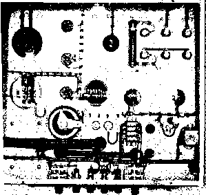 Bridge supplies may also be used to advantage to obtain relatively high plate voltages for high powered transmitting equipment. Type 866-A and 872-A rectifier tubes can only serve in a supply delivering under 3500 volts in a full-wave circuit. Above this voltage, the peak inverse voltage rating of the rectifier tube will be exceeded, and danger of flash-back within the rectifier tube will be present. However, with bridge circuits, the same tubes may deliver up to as much as 7000 volts d.c. without exceeding the peak inverse voltage rating. The bridge circuit also permits the use of the so-called pole transformer in high voltage power supplies. Two KVA transformers of this type having a 110/220 volt secondary winding and a split 2200 volt primary winding may often be picked up in salvage yards for a dollar or two. If reversed, and either 110 or 220 volts applied to the primary winding approximately 2200 volts r.m.s. will be developed across the new secondary winding. If used in a bridge circuit as shown in Figure 38 UNDER-CHASSIS POWER SUPPLY ASSEMBLY AW components are firmly mounted to the sfeel chassis and all wiring is cabled. High voltage leads are run in automobile ignition cables. Heavy-duty terminal strips are mounted along the rear edge of the chassis. The control panel of this supply is shown in figure 7 of this chapter. 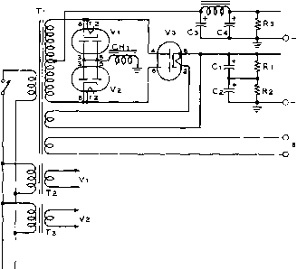 O+H.V, 2 0 + H.V. t Т2,ТЗ = 6.3 V, 1 A. stancor p-ei34
115 V. 50-601 Figure 39 DUAL VOLTAGE BRIDGE POWER SUPPLIES figure 40, a d-c supply voltage of about 1900 volts at a current of 500 milliamperes may be drawn from such a transformer. Do not attempt to use a smaller transformer than the 2-KVA rating, as the voltage regulation of the unit will be too poor for practical purposes. For higher voltages, a pole transformer with a 4400 volt primary and a 110/220 volt secondary may be reversed to provide a d-c plate supply of about 3800 volts. Commercial plate transformers intended for full wave rectifier service may also be used in bridge service provided that the insulation at the center-tap point of the high voltage winding is sufficient to withstand one-half of the r.m.s. voltage of the secondary winding. Many high voltage transformers are specifically designed for operation with the center-tap of the secondary winding at ground potential; consequently the insulation of the winding at this point is not designed to withstand high voltage. It is best to check with the manufacturer of the transformer and find out if the insulation will withstand the increased volt- age before a full wave-type transformer is utihzed in bridge rectifier service. 32-11 300 Volt, 50 Ma. Power Supply There are many appUcations in the laboratory and amateur station for a simple low drain power supply. The most common appli- 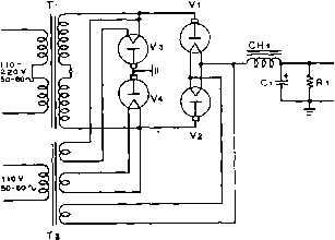 Figure 40 HIGH-VOLTAGE POWER SUPPLY
 cation in the amateur station for such a supply is for items of test equipment such as the type LM and BC-221 frequency meters, for frequency converters to be used in conjunction with the station receiver, and for auxiliary equipment such as high selectivity i-f strips or variable frequency oscillators. Equipments such as these may be operated from a supply dehvering 250 to 300 volts at up to 50 milhamperes of plate current. A filament source of 6.3 or 12 volts may also be required, as will a source of regulated voltage. The simple power supply iUustrated in figures 41 and 42 is capable of meeting these requirements. A two section capacitor input filter system is employed to provide minimum ripple content and a switch (Sz) is provided to insert a VR-150 regulator tube in the circuit to provide 150 volts at approximately 3 5 milliamperes. A separate 6.3 volt filament transformer is connected in series with the 6.3 volt winding of power transformer Ti to provide 12.6 volts at 1.2 amperes for operating 12 volt tubes or a string of two 6 volt tubes connected in series. The secondary winding of Ta must be polarized correctly to provide 12.6 volts across the two windings. Resistor Rl must be adjusted to fire the voltage regulator tube. It should be adjusted so that approximately 15 milliamperes pass through the tube. For maximum permissible current drain from the high voltage tap of the supply the VR tube should be switched out of the circuit. 32-12 500 Volt 200 Milliampere Power Supply The availability of inexpensive TV-type Figure 41 TYPICAL LIGHT DUTY POWER SUPPLY This 300 volt, SO milliampere power supply may be used to run signal generators, frequency meters, small receivers, etc. Switch Si (see schematic) is placed on the rear of the chassis near the line cord. components makes possible the construction of a sturdy 100 watt power supply at a relatively modest price. This power unit is suitable for operating a 50 watt phone/c-w transmitter, a small modulator, or a 100 watt sideband linear amplifier. Maximum intermittent output rating is 500 volts at 200 milliamperes and 6.3 volts at 7 amperes. The circuit of the supply is shown in figure 44 and is designed around a voltage-doubler type power transformer (Stancor P-8336) having a 117 vok, 280 miUiam-pere secondary and three 6.3 volt filament windings. The transformer has a 140 watt core and is conservatively rated. In quadrupler service, 100 watts of power may be taken from the high voltage secondary winding provided the filament current drain is held to 40 watts. Under these limitations, the transformer can run for an hour or so before the core becomes warm to the touch. Four replacement-type selenium rectifiers are used in a simple quadrupler circuit. Although 500 ma. rectifiers are shown, 200 ma. units will work as well. Five ohm surge resistors are employed to limit the starting current of the filter system. Regulation of the 5y3-Gr 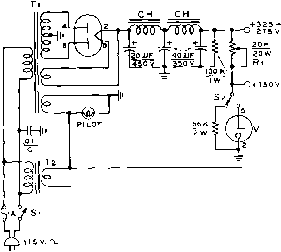 RI50 О 6.3 V. cta,6v. Figure 42 SCHEMATIC, LIGHT DUTY SUPPLY Ti-350 - 0 - 350 volts at 50 milliamperes, 5 volts at 2 amperes, 6.3 volts at 3 amperes, replacement transformer, Тг-6.3 volts at 1.2 amp. Stancor P-6134 CH-4.5 henry at 50 ma. Stancor C-1706 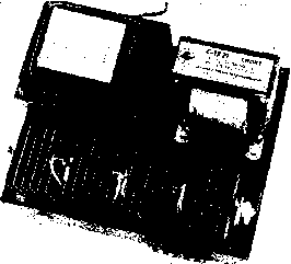 Figure 43 100 WATT ECONOMY MODEL POWER SUPPLY Employing a TV-type voltage doubler transformer and inexpensive selenium rectifiers, tills supply delivers SOO volts at 200 milliamperes with good regulation. The selenium rectifiers are mounted on a long 6-32 bolt fastened to two upright posts mounted at each front corner of the chassis. supply is good, the voltage dropping from 600 voks at no load to 500 volts at maximum current drain. The supply is built upon a steel chassis measuring 9 x6 x2 . The filter capacitors are mounted in the under-chassis area on phenolic tie-point strips. All transformer leads are left their full length so that the transformer will be in usable shape in the event it is eventually used in a different piece of equipment. 32-13 1500 Volt 425 Miiliampere Power Supply One of the most popular and also one of the most convenient power ranges for amateur equipment is that which can be supplied from a 1500 volt power unit with a current capability of about 400 ma. The r-f amplifier of an A-M phone transmitter (1500 volts at 250 ma.) capable of 375 watts input and its companion modulator (1500 volts at 20-200 ma.) can both be run from a supply of this rating. The use of this supply for SSB work will permit a p.e.p. of about 600 watts (1500 volts at 400 ma.) with the new low voltage, high current RCA 7094 tetrodes. This voltage will be found to be very economical when the cost of power supply components is computed. A jump in supply voltage to 2000 will almost double the cost of the various components. Unless full kilowatt operation is Intended, 1500 voks is a very convenient and relatively economical compromise voltage. о о о §117 S 1001JF 10W ISOV. SR4 low : eojjF 350 V. 100 JF e.3V. 150 V. 3V. AT A. 115V. rx,
+500 V AT 200 MA. 6.3 V, 6,3 V. Figure 44 SCHEMATIC, ECONOMY SUPPLY Tj-7 77 volt secondary rated at 280 ma. for doubler service. Three 6.3 volt tjloment ivindings. Stancor P-8336. CH,-8.5 henry at 200 ma, Stancor C-I72I. SRi-SRi-500 ma. selenium rectifier. Sorlces-Tarzian or equivalent. The schematic of a typical supply Is shown in figure 46. Primary power source may be either 115 or 230 volts, the latter providing slightly better power supply regulation. The two transformer primaries are connected in series for 230 volt operation, or in parallel far 115 volt operation. In addition the primaries may be connected in series for half-voltage operation on 115 volts as shown. The supply provides 750 volts at 400 ma. under this operating condition. For optimum dynamic voltage regulation under varying loads such as imposed by sideband or class В modulator equipment the output filter capacitor of the supply should  Figure 45 UNDER-CHASSIS VIEW OF ECONOMY SUPPLY Two 20 fifd., 4S0 volt capacitors are connected in parallel for each 80 iifd. unit. 115 V. RELAY C0NTW5L RYl ад о о о о о о о о о о о о ЕАСИ = 450 V. S-£- -о lbOO/750V. AT 425 МА. 35К. SOW 35 К 551 Figure 46 SCHEMATIC, 1500 VOLT, 425 MILLIAMPERE SUPPLY Tl-1710 - 0 - 1710 Yolis, 425 ma. 115/230 volt primary. Chicago P-1512 Тг-2.5 volt, 10 ampere, 10 KV iiisulation. 5fancor P-3060 CHl-6 henry of 300 ma CCS, Chicago R-63 RFC- Hash suppresslort choke. Millen 77866 be as large as is practical. Occasionally 60 /Lifd., 2000 volt capacitors can be picked up on the surplus market for a few dollars, although their new price would give most amateurs pause for thought. An inexpensive and reliable substimte may be made up of a group of replacement-type tubular electrolytic capacitors connected in series-parallel as shown in the schematic. Eight 30 fiid., 450 volt capacitors connected in series parallel will provide an effective value of 15 fjdd., at a working voltage of 1800. This is the minimum value suitable for sideband operation. Sixteen capacitors will provide 30 fiid., at 1800 volts. A power supply of this type should be built upon a heavy steel chassis, and all wiring must be done with 10,000 volt TV-type plastic insulated wire. R-F chokes should be placed in the plate leads of the mercury vapor rectifiers as shown, to reduce the tendency these tubes have of breaking into oscillation over a portion of the operating cycle. Oscillation of this type will produce a 120 cycle buzz on the sidebands of the signal. The parasitic is eliminated by the use of the chokes. 32-14 A Dual Volfage TransmiHer Supply The majority of high voltage transformers have tapped secondary windings, similar to the transformer shown in the schematic of figure 47. Separate rectifier and filter systems may be used with the transformer to provide two different ourput voltages provided the total wattage drain from rhe supply does not exceed the wattage rating of the transformer. The drain may be divided between the two supply systems in any manner desired. The intermittent rating of Тг (figure 47) is 750 watts and the continuous duty rating is 600 watts. Under CCS rating, the supply can provide (for example) 2000 volts at l60 ma. for the operarion of an 813 r-f amplifier at 320 watts input, and 1750 volts at 20-150 ma. for the operation of 811-A class В modulators. Under intermittent duty rating, the 813 amplifier can run at 400 watts input (phone) and 500 watts (c-w) without overloading the supply. A remote switch is used to energize the plate circuit relay of the supply. An auxiliary antenna relay is also operated by the transmit switch. 32-15 A Kilowaff Power Supply Shown in figure 48 is the schematic of a power supply capable of dehvering 2500 volts at a continuous current drain of 500 milliamperes, or 700 milliamperes with an intermittent load. The supply is designed to power a kilowatt amplifier operating at 2500 volts and 400 ma., in conjunction with a 500 watt modulator operating at 2500 volts at a vary- 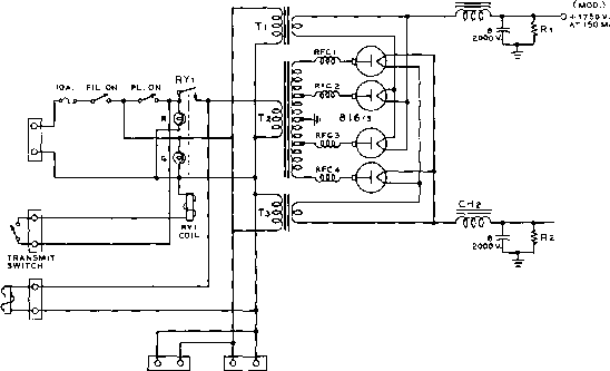 ANTENNA RELAY (R.F.) О + гооо V. AT leOMA. R.F. FIL. MOD. FIL. Figure 47 DUAL VOLTAGE POWER SUPPLY T Тз-2.5 volts at 5 amperes. Stancor P-6I33 Ti-2400-2 700 volts each side center tap at 375 ma. ICAS. Stancor P-8032 CHi-3 to 17 henry, 300 ma. Stancor C-7403 CHt-8 henry, 300 mo., Stancor C-J4I3 Ri, Ri-70K., 700 watt RFC, RFCi- Hash suppression choke. J. V/. Miller 7865 twin chokes 12 rea.) RYj-SPST relay, IIS volt coil. ing current drain of 50-300 ma. Specifically, the supply is employed with a transmitter having a pair of 4-250A tetrode tubes in the class С stage, and a pair of 810 modulator tubes. For sideband work, the supply may be used to power a 1750 watt p.e.p. linear amplifier, such as the 4CX-1000A amphfier shown in an earlier chapter. Because the total weight of the components is over 150 pounds, tbe supply should be built directly on the bottom of a relay rack instead of upon a steel chassis. The r-f hash suppression chokes RFC and RFCa are fastened directly to the high voltage terminals of the plate transformer. The two 872-A rectifier tubes are so located that the leads from the r-f chokes to the plate caps are only about three inches long. A 0.15 jufd., 5000 volt paper capacitor is used to resonate the filter choke to approximately 120 cycles at a bleeder current of 25 milliamperes. When full load current is drawn, the inductance of the filter choke drops, detuning the parallel resonant circuit. Improved voltage regulation is gained by this action; the no load voltage increases only 200 volts over the full load voltage. 872aS 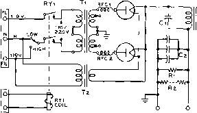 TO EXCITER CONTROL CIRCUIT - 2500 v, + Tl-2900-0-2900 VOLTS AT 700 MA., ICAS, CH/CASO P-2Z6 t2-5 VOLTS, 10 AMP., CHICAGO F-SIOH CHl-6 HENRIES, TOOMA. CHICAGO R-e? Cl-0.15ilF, 5000-V0LT. Сг-THREE 4-UF 3000-VOLT Rl-100.000 OHMS. ZOO-WATT. RZ-ELEVEN 0.5 MEG. Z-WATT RESISTORS IN SERIES RYl - DPST RELAY, 110 V. COIL, 20 A, CONTACTS, POTTER BHUMflELD PR 7 A RFCl, rfc2-HA5H FILTER, J.W. MILLER CO. N 7863 Figure 48 HIGH VOLTAGE POWER SUPPLY CHAPTER THIRTY-THREE  With a few possible exceptions, such as fixed air capacitors, neutralizing capacitors and transmitting coils, it hardly pays one to attempt to build the components required for the construction of an amateur transmitter. This is especially true when the parts are of the type used in construction and replacement work on broadcast receivers, as mass production has made these parts very inexpensive. Transmitters Those who have and wish to spend the necessary rime can effect considerable monetary saving in their transmitters by building them from the component parts. The necessary data is given in the construction chapters of this handbook. To many builders, the construction is as fascinating as the operation of the finished transmitter; in fact, many amateurs get so much satisfaction out of building a well-performing piece of equipment that they spend more time constructing and rebuilding equipment than they do operating the equipment on the air. 33-1 Tools Beautiful work can be done with metal chassis and panels with the help of only a few inexpensive tools. The time required for construction, however, will be greatly reduced if a fairly complete assortment of metal-working tools is available. Thus, while an array of tools will speed up the work, excellent results may be accomplished with few tools, if one has the time and patience. The investment one is justified in making in tools is dependent upon several factors. If you like to tinker, there are many tools useful in radio construction that you would probably buy anyway, or perhaps already have, such as screwdrivers, hammer, saws, square, vise, files, etc. This means that the money taken for tools from your radio budget can be used to buy the more specialized tools, such as socket punches or hole saws, taps and dies, etc The amount of construction work one does determines whether buying a large assortment 1 ... 68 69 70 71 72 73 74 ... 80 |
||||||||||||||||||||||||||||||||||||||||||||||||||||||||||||||||||||||||||||||||||||||||||||||||||||||||||||||||||||||||||||||||||||||||||||||||||||||||||||||||||||||||||||||||||||||||||||||||||||||||||||||||||||||||||||||||||||||||||||||||||||||||||||||||||||||||||||||||||||||||||||||||||||||||||||||||||||||||||||||||||
|
© 2026 AutoElektrix.ru
Частичное копирование материалов разрешено при условии активной ссылки |