 |
 |
 |
| Главная Журналы Популярное Audi - почему их так назвали? Как появилась марка Bmw? Откуда появился Lexus? Достижения и устремления Mercedes-Benz Первые модели Chevrolet Электромобиль Nissan Leaf |
Главная » Журналы » Simple coaxial reflectometer 1 ... 69 70 71 72 73 74 75 ... 80 of tools is an economical move. It also determines if one should buy the less expensive type offered at surprisingly low prices by the familiar mail order houses, five and ten stores and chain auto-supply stores, or whether one should spend more money and get first-grade tools. The latter cost considerably more and work but little better when new, but will outlast several sets of the cheaper tools. Therefore they are a wise investment for the experimenter who does lots of construction work (if he can afford the initial cash outlay). The amateur who constructs only an occasional piece of apparatus need not be so concerned with tool life, as even the cheaper grade tools will last him several years, if they are given proper care. The hand tools and materials in the accompanying lists will be found very useful around the home workshop. Materials not listed but ordinarily used, such as paint, can best be purchased as required for each individual job. ESSENTIAL HAND TOOLS AND MATERIALS 1 Good electric soldering iron, about 100 watts, 1 Spool rosin-core wire solder 1 Each large, medium, small, and midget screwdrivers 1 Good hand drill (eggbeater type), preferably two-speed 1 Pair regular pliers, 6 inch 1 Pair long nose pliers, 6 inch 1 Pair cutting phers (diagonals), 5 inch or 6 inch 1 11/8-inch tube-socket punch 1 Boy Scout knife 1 Combination square and steel rule, 1 foot 1 Yardstick or steel pushrule 1 Scratch awl or ice pick scribe 1 Center punch 1 Dozen or more assorted round shank drills (as many as you can afford between no. 50 and 1/4 or inch, depending upon size of hand drill chuck) 1 Combination oil stone Light machine oil (in squirt can) Friction tape 1 Hacksaw and blades 1 Medium file and handle 1 Cold chisel (V2 inch tip) 1 Wrench for socket punch 1 Hammer HIGHLY DESIRABLE HAND TOOLS AND MATEiaALS 1 Bench vise (jaws at least 3 inch) 1 Spool plain wire solder 1 Carpenters brace, ratchet type 1 Square-shank countersink bit 1 Square-shank taper reamer, small 1 Square-shank taper reamer, large (the two reamers should overlap; У2 inch and inch size will usually be suitable) 1 % inch tube-socket punch (for electrolytic capacitors) 1 1-3/16 inch rube-socket punch 1 5-inch tube-socket punch 1 Adjustable circle cutter for holes to 3 inch 1 Set small, inexpensive, open-end wrenches 1 Pair tin shears, 10 or 12 inch 1 Wood chisel iVi inch tip) 1 Pair wing dividers 1 Coarse mill file, flat 12 inch 1 Coarse bastard file, round, У2 or з4 inch 1 Set alien and spline-head wrenches 6 or 8 Assorted small files; round, half-round or triangular, flat, square, rat-tail 4 Small C clamps Steel wool, coarse and fine Sandpaper and emery cloth, coarse, medium, and fine Duco cement File brush USEFUL BUT NOT ESSENTIAL TOOLS AND MATERIALS 1 Jig or scroll saw (small) with metal-cutting blades 1 Small wood saw (crosscut teeth) 1 Each square-shank drills: У%, 7/16, and У2 inch 1 Tap and die outfit for 6-32, 8-32, 10-32 and 10-24 machine screw threads 4 Medium size C clamps Lard oil (in squirt can) Kerosene Empire cloth Clear lacquer ( industrial grade) Lacquer thinner Dusting brush Paint brushes Sheet celluloid, Lucite, or polystyrene 1 Carpenters plane 1 Each Spintite wrenches, ц, 5/16, 11/32 to fit the standard 6-32 and 8-32 nuts used in radio work 1 Screwdriver for recessed head type screws The foregoing assortment assumes that the constructor does not want to invest in the more expensive power tools, such as drill press. 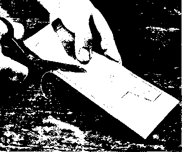 THE RADIO Figure 1 SOFT ALUMINUM SHEET MAY BE CUT WITH HEAVY KITCHEN SHEARS grinding head, etc. If power equipment is purchased, obviously some of the hand tools and accessories listed will be superfluous. A drill press greatly facilitates construction work, and it is unfortunate that a good one costs as much as a small transmitter. Not listed in the table are several special-purpose radio tools which are somewhat of a luxury, but are nevertheless quite handy, such as various around-the-corner screwdrivers and wrenches, special soldering iron tips, etc. These can be found in the larger radio parts stores and are usually listed in their mail order catalogs. If it is contemplated to use the newer and very popular miniarure series of tubes (6AK5, 6C4, 6BA6, etc.) in the construction of equipment certain additional tools will be required to mount the smaller components. Miniature tube sockets mount in a %-inch hole, while 9-pin sockets mount in a -inch hole. Greenlee socket punches can be obtained in these sizes, or a smaller hole may be reamed to the proper size. Needless to say, the punch is much the more satisfactory solution. Mounting screws for miniature sockets are usually of the 4-40 size. Metal Chassis Though quite a few more tools and considerably more time will be required for metal chassis construction, much neater and more satisfaaory equipment can be built by mounting the parts on sheet metal chassis instead of breadboards. This type of construction is necessary when shielding of the appartus is required. A front panel and a back shield minimize the danger of shock and complete the shielding of the enclosure.  Figure 2 CONVENTIONAL WOOD EXPANSION BIT IS EFFECTIVE IN DRILLING SOCKET HOLES IN REYNOLDS DO-IT-YOURSELF ALUMINUM Figure 3 SOFT ALUMINUM TUBING MAY BE BENT AROUND WOODEN FORM BLOCKS. TO PREVENT THE TUBE FROM COLLAPSING ON SHARP BENDS, IT IS PACKED WITH WET SAND. 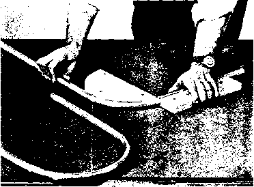 33-2 The Material Electronic equipment may be built upon foundation of wood, steel or aluminum. The choice of foundation material is governed by the requirements of the electrical circuit, the weight of the components of the assembly, and the financial cost of the project when balanced against the pocketbook contents of the constructor. Breodboard The simplest method of constructing equipment is to lay it out in breadboard fashion, which consists of fastening the various components to a board of suitable size with wood screws or machine bolts, arranging the parts so that important leads will be as short as possible. Breadboard construction is suitable for testing an experimental layout, or sometimes for assembling an experimental unit of test equipment. But no permanent item of station equipment should be left in the breadboard form. Breadboard construction is dangerous, since components carrying dangerous voltages are left exposed. Also, breadboard construction is never suitable for any r-f portion of a transmitter, since it would be substantially impossible to shield such an item of equipment for the elimination of TVI resulting from harmonic radiation. Figure 4 A WOODWORKING PLANE MAY BE USED TO SMOOTH OR TRIM THE EDGES OF REYNOLDS DO-IT-YOURSELF ALUMINUM STOCK. Dish type construction is practically the some as metal chassis construaion, the main difference lying in the manner in which the chassis is fastened to the panel. Special For high-powered r-f stages, Frameworks many amateur constructors prefer to discard the more conventional types of construction and employ instead special metal frameworks and brackets which they design specially for the parts which they intend to use. These are usually arranged to give the shortest possible r-f leads and to fasten directly behind a relay rack panel by means of a few bolts, with the control shafts 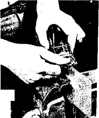 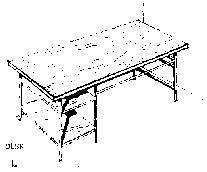 COMPONENT PARTS 1. Legs and stringers - aluminum angle M xYi 2. Top-flush door 3. Shelves-Й plywood 50 ---4 - yg- 50 - - 25 - О'б - T - 2v- Figure 5 INEXPENSIVE OPERATING DESK MADE FROM ALUMINUM ANGLE STOCK, PLY-WOOD AND A FLUSH-TYPE DOOR projecting through corresponding holes in the panel. Working with The necessity of employing Aluminum electrically right enclosures for the containment of TVI-producing harmonics has led to the general use of. aluminum for chassis, panel, and enclosure construction. If rhe proper type of aluminum material is used, it may be cut and worked with the usual woodworking tools found in the home shop. Hard, brittle aluminum alloys such as 24ST and 61ST should be avoided, and the softer materials such as 2S or 1/2 H should be employed. A new market product is Reynolds Do-it-yourself aluminum, which is being distributed on a nationwide basis through hardware stores, lumber yards and building material outlets. This material is an alloy which is temper selected for easy working with ordinary tools. Aluminum sheet, bar and angle stock may be obtained, as well as perforated sheets for ventilated enclosures. Figures 1 through 4 illustrate how this soft material may be cut and worked with ordinary shop tools, and fig. 5 shows a simple operating desk that may be made from aluminum angle stock, plywood and a flush-type six foot door.  Figure 6 TVI ENCLOSURE MADE FROM SINGLE SHEET OF PERFORATED ALUMINUM Reynolds Metal Co. Do-it-yourself aluminum sheet may be cut and folded to form TYI-proof enclosure. One-half inch lip on edges Is bolted to center section with 6-32 machine screws. 33-3 TVI-Proof Enclosures Armed with a right-angle square, a tin-snips and a straight edge, the home constructor will find the assembly of aluminum enclosures an easy task. This section will show simple con-strucrion methods, and short cuts in producing enclosures. The simplest type of aluminum enclosure is that formed from a single sheet of perforated material as shown in figure 6. The top, sides, and back of the enclosure are of one piece, complete with folds that permit the formed enclosure to be bolted together along the edges. The top area of the enclosure should match the area of rhe chassis to ensure a close fit. The front edge of the enclosure is attached to aluminum angle strips that are bolted to the front panel of the unit; the sides and back can either be bolted to matching angle strips affixed to the chassis, or may simply be attached to the edge of the chassis with self-tapping sheet metal screws. Enclosures of this type are used on the all-band transmitter described in chapter 31. A more sophisticated enclosure is shown in figure 7. In this assembly aluminum angle stock is cut to length to form a framework upon which the individual sides, back, and top of the enclosure are bolted. For greatest strength, small aluminum gusset plates should be affixed in each corner of the enclosure. The complere assembly may be held together by no. 6 sheet metal screws. Regardless of the type of enclosure to be made, care should be taken to ensure that all joints are square. Do not assume that all prefabricated chassis and panel are absolutely true and square. Check them before you start Ю form your shield as any dimensional errors in the foundation will cause endless patching and cutting after your enclosure is bolted together. Finally, be sure that paint is removed from the panel and chassis at the point the enclosure attaches to the foundation. A clean, metallic contact along the seam is required for maximum harmonic suppression. 33-4 Enclosure Openings Openings into shielded enclosures may be made simply by covering them by a piece of shielding held in place by sheet metal screws. Openings through vertical panels, however, usually require a bit more attention to prevent leakage of harmonic energy through the crack of the door which is supposed to seal the opening. A simple way to provide a panel opening is to employ the Bud ventilated door rack panel model PS-814 or 813. The grille opening in this panel has holes small enough in area to prevent serious harmonic leakage. The actual door opening, however, does not seal tightly enough to be called TVI-proof. In areas of high TV signal strength where a minimum of operation on 28 Mc. is contemplated, the door is satisfactory as is. To accomplish more complete harmonic suppression, the edges of the opening should be lined with preformed contact finger stock manufactured by Eitel-McCullough, Inc., of San Bruno, Calif. Eimac finger stock is an excellent means of providing good jcontact continuity when using components with adjustable or moving contact surfaces, or in acting as electrical weatherstrip around access doors in enclosures. Harmonic leakage through such a sealed opening is reduced to a negligible level. The mating surface to the finger stock should be free of paint, and should provide a good electrical connection to the stock. A second method of re-establishing electrical continuity across an access port is со employ Metex shielding around the mating edges of the opening. Metex is a flexible knitted wire mesh which may be obtained in various sizes and shapes. This r-f gasket material is produced by Metal Textile Corp., Roselle, N.J. Metex is both flexible and resilient and conforms to irregularities in mating surfaces with a minimum of closing pressure.  Figure 7 TVI-PROOF ENCLOSURE BUILT OF PERFORATED ALUMINUM SHEET AND ANGLE STOCK 33-5 Summation of the Problem The creation of r-f energy is accompanied by harmonic generation and leakage of fundamental and harmonic energy from the generator source. For practical purposes, radio frequency power may be considered as a form of both electrical and r-f energy. As electrical energy, it will travel along any convenient conductor. As r-f energy, it will radiate directly from the source or from any conductor connected to the source. In view of this dual регюпаИгу of r-f emanations, there is no panacea for all forms of r-f energy leakage. The cure involves both filtering and shielding: one to block the paths of conducted energy, the other to prevent the leakage of radiated energy. The proper combination of filtering and shielding can reduce the radiation of harmonic energy from a signal source some 80 decibels. In most cases, this is sufficient to eliminate interference caused by the generation of undesirable harmonics. 33-6 Construction Practice Chassis The chassis first should be covered Layout with a layer of wrapping paper, which is drawn tightly down on all sides and fastened with scotch tape. This allows any number of measurement lines and hole centers to be spotted in the correct positions without making any marks on the chassis itself. Place on it the parts to be mounted and play a game of chess with them, trying different arrangements until all the grid and plate leads are made as short as possible, tubes are clear of coil fields, r-f chokes are in safe positions, etc. Remember, especially if you are going to use a panel, that a good mechanical layout often can accompany sound electrical design, but that the electrical de-siign should be given first consideration. All too often parts are grouped to give a symmetrical panel, irrespective of the arrangement behind. When a satisfactory arrangement lias been reached, the mounting holes may be marked. The same procedure now must be followed for the underside, always being careful to see that there are no clashes between the two (that no top mounting screws come down into the middle of a paper capacitor on the underside, that the variable capacitor rotors do not hit anything when turned, etc.). When all the holes have been spotted, they should be center-punched through the paper into the chassis. Dont forget to spot holes for leads which must also come through the chassis. For transformers which have lugs on the bottoms, the clearance holes may be spotted by pressing the transformer on a piece of paper to obtain impressions, which may then be transferred to the chassis. Punching In cutting socket holes, one can use either a fly-cutter or socket punches. These punches are easy to operate and only a few precautions are necessary. The guide pin should fit snugly in the guide hole. This increases the accuracy of location of the socket. If this is not of great importance, one may well use a drill of 1/32 inch larger diameter than the guide pin. Some of the punches will operate without guide holes, but the latter always make the punching operations simpler and easier. The only other precaution is to be sure the work is properly lined up before applying the hammer. If this is not done, the punch may slide sideways when you strike and thus not only shear the chassis but also take   О ® DRILL HOLES SLIGHTLY BREAH OUT INSIDE DASHED OUTLINE PIECE INSIDE OF DESIRED HOLE. DRILL HOLES. ® FILE SMOOTH MAKING RECTANGULAR CUTOUT Figure 8 off part of the die. This is easily avoided by always making sure that the piece is parallel to the faces of the punch, the die, and the base. The latter should be an anvil or other solid base of heavy material. A punch by Greenlee forces socket holes through the chassis by means of a screw turned with a wrench. It is noiseless, and works much more easily and accurately than most others. The male part of the punch should be placed in the vise, cutting edge up and the female portion forced against the metal with a wrench. These punches can be obtained in sizes to accommodate all tube sockets and even large enough to be used for meter holes. In the octal socket sizes they require the use oi a Ys inch center hole to accommodate the bolt. Transformer Cutouts for transformers and Cutouts chokes are not so simply han- dled. After marking off the part to be cut, drill about a У4-[псЪ hole on each of the inside corners and tangential to the edges. After burring the holes, clamp the piece and a block of cast iron or steel in the vise. Then, take your burring chisel and insert it in one of the corner holes. Cut out the metal by hitting the chisel with a hammer. The blows should be light and numerous. The chisel acts against the block in the same way that the two blades of a pair of scissors work against each other. This same process is repeated for the other sides. A file is used to trim up the completed cutout. Another method is to drill the four corner holes large enough to take a hack saw blade, then saw instead of chisel. The four holes permit nice looking corners. Still another method is shown in figure 8. When heavy panel steel is used and a drill press or electric drill is available, this is the most satisfactory method. Removing In both drilling and punching, a Burrs burr is usually left on the work. There are three simple ways of removing these. Perhaps the best is to take a chisel (be sure it is one for use on metal) and set it so that its bottom face is parallel to the piece. Then gently tap it with a hammer. This usually will make a clean job with a little practice. If one has access to a counterbore, this will also do a nice job. A countersink will work, although it bevels the edges. A drill of several sizes larger is a much used arrangement. The third method is by filing off the burr, which does a good job but scratches the adjacent metal surfaces badly. Mounting There are two methods in gen-Components eral use for the fastening of transformers, chokes, and similar
Figure 9 pieces of apparatus to chassis or breadboards. The first, using nuts and machine screws, is slow, and the commercial manufacturing practice of using self-tapping screws is gaining favor. For the mounting of small parts such as resistors and capacitors, tie points are very useful to gain rigidity. They also contribute materially to the appearance of finished apparatus. Rubber grommets of the proper size, placed in all chassis holes through which wires are to be passed, will give a neater appearing job and also will reduce the possibility of short circuits. Soldering Making a strong, low-resistance solder joint does not mean just dropping a blob of solder on the two parts to be joined and then hoping that theyll stick. There are several definite rules that must be observed. All parts to be soldered must be absolutely clean. To clean a wire, lug, or whatever it may be, take your pocket knife and scrape it thoroughly, until fresh metal is laid bare. It is not enough to make a few streaks; scrape until the part to be soldered is bright. Make a good mechanical joint before applying any solder. Solder Is intended primarily to make a good electrical connection; mechanical rigidity should be obtained by bending the wire into a small hook at the end and nipping it firmly around the other part, so that it will hold well even before the solder is applied. Keep your iron properly tinned. It is impossible to get the work hot enough to take the solder properly if the iron is dirty. To tin your iron, file it, while hot, on one side until a full surface of clean metal is exposed. Immediately apply rosin core solder until a thin layer flows completely over the exposed surface. Repeat for the other faces. Then take a clean rag and wipe off all excess solder and rosin. The iron should also be wiped frequently while the actual construction is going on; it helps prevent pitting the tip. Apply the solder to the work, not to the iron. The iron should be held against the parts to be joined until they are thoroughly heated. The solder should then be applied against the parts, and the iron should be held in place until the solder flows smoothly and envelopes the work. If it acts like water on a greasy plate, and forms a ball, the work is not sufficiently clean. The completed joint must be held perfectly still until the solder has had time to solidify. If the work is moved before the solder has be- OjHffljjIsPOOL of wire sta Rt\ fi n1sh form of bakelite or other uood insulating material. finished COIL WINDING COIL ON INSULATING FORM Figure 10 pipe or rod used as temporary form,  wind turns close together and space later. WINDING AIR-SUPPORTED COIL Figure 11 come completely solid, a cold joint will result. This can be identified immediately, because the solder will have a dull white appearance rather than one of shiny silver. Such joints tend to be of high resistance and will very likely have a bad effect upon a circuit. The cure is simple, merely reheat the joint and do the job correctly. Wipe away all surplus flux when the joint has cooled if you are using a paste type flux. Be sure it is non-corrosive, and use it with plain (not rosin core) solder. Finishes If the apparatus is constructed on a painted chassis (commonly available in black wrinkle and gray wrinkle), there is no need for application of a protective coating when the equipment is finished, assuming that you are careful not to scratch or mar the finish while drilling holes and mounting parts. However, many amateurs prefer to use un-painted (zinc or cadmium plated) chassis, because it is much simpler to make a chassis ground connection with this type of chassis. A thin coat of clear linoleum lacquer may be applied to the whole chassis after the wiring is completed to retard rusting. In localities near the sea coast it is a good idea to lacquer the various chassis cutouts even on a painted chassis, as rust will get a good start at these points unless the metal is protected where the drill or saw has exposed it. If too thick a coat is applied, the lacquer will tend to peel. It may be thinned with lacquer thinner to permit application of a light coat. A thin coat will adhere to any clean metal surface that is not too shiny. An attractive dull gloss finish, almost velvety can be put on aluminum by sand-blasting it with a very weak blast and fine particles and then lacquering it. Soaking the aluminum in a solution of lye produces somewhat the same effect as a fine grain sand blast. There are also several brands of dull gloss black enamels on the market which adhere well to metals and make a nice appearance. Airdrying wrinkle finishes are sometimes successful, but a bake job is usually far better. Wrinkle finishes, properly applied, are very durable and are pleasing to the eye. If you live in a large community, there is probably an enameling concern which can wrinkle your work for you at a reasonable cost. A very attractive finish, for panels especially, is to spray a wrinkle finish with aluminum paint. In any painting operation (or plating, either, for that matter), the work should be very thoroughly cleaned of all greases and oils. To protect brass from tarnish, thoroughly cleanse and remove the last trace of grease by the use of potash and water. The brass must be carefully rinsed with water and dried; but in doing it, care must be taken not to handle any portion with the bare hands or anjthing else that is greasy. Then lacquer. Winding Coils Coils are of two general types, those using a form and air-wound types. Neither type offers any particular constructional difficulties. Figure 10 illustrates the prcxiedure used in form winding a coil. If the winding is to be spaced, the spacing can be done either by eye or a string or another piece of wire may be wound simultaneously with the coil wire and removed after the winding is in place. The usual procedure is to clamp one end of the wire in a vise, attaching the other end to the coil form and with the coil form in hand, walk slowly towards the vise winding the wire but at the same time keeping a strong tension on the wire as the form is rotated. After the coil is wound, if there is any possibility of the turns slipping, the completed coil is either entirely coated with a coil or Duco cement or cemented in those spots where slippage might occur. �9999 Figure 12 GOOD SHOP LAYOUT AIDS CAREFUL WORKMANSHIP Built in a corner of a garage, tftis sfiop lias all features necessary for electronic work. Test instruments are arranged on shelves above bench. Numerous outlets reduce haywire produced by tangled line cords. Not shown in picture are drill press and sander at end of left bench 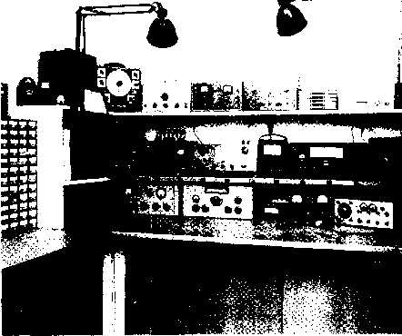 V-h-f and u-h-f coils are commonly wound of heavy enameled wire on a form and then removed from the form as in figure 11. If the coil is long or has a tendency to buckle, strips of polystyrene or a similar material may be cemented longitudinally inside the coil. Due allowance must be made for the coil springing out when removed from the form, when selecting the diameter of the form. On air wound coils of this type, spacing between turns is accomplished after removal from the form, by running a pencil, the shank of a screwdriver or other round object spirally between the turns from one end of the coil to the other, again making due allowance for spring. Air-wound coils, approaching the appearance of commercially manufactured ones, can be constructed by using a round wooden form which has been sawed diagonally from end to end. Strips of insulating material are temporarily attached to this mandrel, the wire then being wound over these strips with the desired separation between turns and cemented to the strips. When dry, the split mandrel may be removed by unwedging it. 33-7 Shop Layout The size of your workshop Is relatively unimportant since the shop layout will determine its efficiency and the ease with which you may complete your work. Shown in figure 12 is a workshop built into a 10x10 area in the corner of a garage. The workbench is 32 wide, made up of four strips of 2 x8 lumber supported on a solid framework made of 2 x4 lumber. The top of the workbench is covered with hard-surface Masonite. The edge of the surface is protected with aluminum counter edging strip, obtainable at large hardware stores. Two wooden shelves 12 wide are placed above the bench to hold the various items of test equipment. The shelves are bolted to the wall studs with large angle brackets and have wooden end pieces. Along the edge of the lower sihelf a metal outlet strip is placed that has an 115-volt outlet every six inches along its Length. A similar strip is run along the back of the lower shelf. The front strip is used for equipment that is being bench-tested, and the rear strip powers the various items of test equipment placed on the shelves. At the left of the bench is a storage bin for small components. A file cabinet can be seen at the right of the photograph. This necessary item holds schematics, transformer data sheets, and other papers that normally are lost in the usual clutter and confusion. The area below the workbench has two storage shelves which are concealed by sliding doors made of 14-inch Masonite. Heavier tools, and large components are stored in this area. On the floor and not shown in the photograph is a very necessary item of shop equipment: a large trash receptacle. A compact and efficient shop built in one-half of a wardrobe closet is shown in figure 13. The workbench length is four feet. The top is made of 4 x6 lumber sheathed with hard surface Masonite and trimmed with counter edging strip. The supporting struc- 729-A 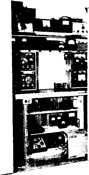 Figure 13 COMPLETE WORKSHOP IN A CLOSET! Careful layout permits complete electronic workshop to be placed in one-half of a word-robe closet. Work bench is built atop an unpointed three-shelf bookcase. шге is made from an unpainted three-shelf bookcase. A 2 x2 leg is placed under the front corners of the bench to provide maximum stability. Atop the bench, a small wooden framework supports needed items of test equipment and a single shelf contains a 115-volt outlet strip. The instruments at the top of the photo are placed on the wardrobe shelf. When not in use, the doors of the wardrobe are closed, concealing the workshop completely from view. 1 ... 69 70 71 72 73 74 75 ... 80 |
|||||||||||||||||||||||||||||||||||||||||||||||||||||||||||||||||||||||||||||||||||||||||||||||||||||||||||||||||||||||||||||||||||||||||||||||||||||||||||||||||||||||||||||||||||||||||||||||||||||||||||||||||||||||||||||||||||||||||||||||||||||||||||||||||||||||||||||||
|
© 2026 AutoElektrix.ru
Частичное копирование материалов разрешено при условии активной ссылки |