 |
 |
 |
| Главная Журналы Популярное Audi - почему их так назвали? Как появилась марка Bmw? Откуда появился Lexus? Достижения и устремления Mercedes-Benz Первые модели Chevrolet Электромобиль Nissan Leaf |
Главная » Журналы » Simple coaxial reflectometer 1 ... 70 71 72 73 74 75 76 ... 80 Electronic Test Equipment All amateur stations are required by kw to have certain items of test equipment available within the station. A c-w station is required to have a frequency meter or other means in addition to the transmitter frequency control for insuring that the transmitted signal is on a frequency within one of the frequency bands assigned for such use. A radiophone station is required in addition to have a means of determining that the transmitter is not being modulated in excess of its modulation capability, and in any event not more than 100 per cent. Further, any station operating with a power input greater than 900 watts is required to have a means of determining the exact input to the final stage of the transmitter, so as to insure that the power input to the plate circuit of the output stage does not exceed 1000 watts. The additional test and measurement equipment required by a station will be determined by the type of operation contemplated. It is desirable that all stations have an accurately calibrated volt-ohmmeter for routine transmitter and receiver checking and as an assistance in getting new pieces of equipment into operation. An oscilloscope and an audio oscillator make a very desirable adjunct to a phone station using AM or FM transmission, and are a necessity if single-sideband operation is contemplated. A calibrated signal generator is almost a necessity if much receiver work is contemplated, although a frequency meter of LM or BC-221 type, particularly if it includes internal modulation, will serve In place of the signal generator. Extensive antenna work in- variably requires the use of some type of field-strength meter, and a standing-wave meter of some type is very helpful. Lastly, if much v-h-f work is to be done, a simple grid-dip meter will be found to be one of the most used items of test equipment in the station. 34-1 Voltage, Current and Power The measurement of voltage and current in radio circuits Is very important in proper maintenance of equipment. Vacuum tubes of the types used in communications work must be operated within rather narrow limits in regard to filament or heater voltage, and they must be operated within certain maximum limits in regard to the voltage and current on other electrodes. Both direct current and voltage are most commonly measured with the aid of an Instrument consisting of a coil that is free to rotate In a constant magnetic field (dArsonval type instrument). If the instrument is to be used for the measurement of current it is called an ammeter or milliammeter. The current flowing through the circuit is caused to flow through the moving coil of this type of instrument. If the current to be measured is greater than 10 milliamperes or so it is the usual practice to cause the majority of the current to flow through a by-pass resistor called a shunt, only a specified portion of the current flowing through the moving coil of the instrument. The calculation of shunts for extending the range of d-c milliammeters and ammeters is discussed in Chapter Two. 721-B о t-fO (MA.) 0-1 DX, + 100 0 +250 0 + 1OO0 о О + 10 MA.) O-I D,C. 10K -Wr- +100 90 к -ЛАЛг- +250 О + 1000 О ISOK 750К -Wl-i-W,- ®  10K -Wj- 90 к -ИМ,- 100 250 150 К 750 К WV-1 Figure 1 MULTI-VOLTMETER CIRCUITS (A) shows a circuit whereby individual multiplier resistors are used for each range. (B) is tbe more economical series multiplier circuit. The same number of resistors is required, but those for the higher ranges have less resistance, and hence are less expensive when precision wirewound resistors are to be used. (C) shows a circuit essentially the same as at (A), except that a range switch is used. With a 0-500 d-c microam-meter substituted for the 0-1 milliammeter shown above, all resistor values would be multiplied by two and tbe voltmeter would have a 2000-ohm-per-volt sensitivity. Similarly, if a 0-50 d-c microammeter were to be used, all resistance values would be multiplied by twenty, and the voltmeter would have a sensitivity of 20,000 ohms per volt. A direct current voUmeter is merely a d-c milliammeter with a multiplier resistor in series with It. If it is desired to use a low-range milliammeter as a voltmeter the value of the multiplier resistor for any voltage range may be determined from the following formula: 1000 E R =- where: R = multiplier resistor in ohms E = desired full scale voltage I = full scale current of meter in ma. The sensitivity of a voltmeter is commonly expressed in ohms per volt. The higher the ohms per volt of a voltmeter the greater its sensitivity. When the full-scale current drain of a voltmeter is known, its sensitivity rating in ohms per volt may be determined by: 1000 Ohms per volt =- 250K гООК 40K [-m-r ®(5V-1 ®- TAP SWITCH (з> 10 к -1 - л и ллл-i - 4.5V. -X-: Figure 2 VOLT-OHMMETER CIRCUIT With the switch In position 1, the 0-1 milliammeter would be connected directly to the terminals. In position 2 the meter would read from 0-100,000 ohms, approximately, with a resistance value of 4500 ohms at half scale. (Note: The half-scale resistance value of an ohmmeter using this circuit is equal to the resistance in series with the battery inside the instrument.) The other tour taps are voltage ranges with 10, SO, 250, and 500 volts full scale. Where I is the full-scale current drain of the indicating instrument in milliamperes. MulH-Ronge It is common practice to connect Meters a group of multiplier resistors in the circuit with a single indicating instrument to obtain a multi-range voltmeter. There are several ways of wiring such a meter, the most common ones of which are indicated in figure 1. With all these methods of connection, the sensitivity of the meter in ohms per volt is the same on all scales. With a 0-1 milliammeter as shown the sensitivity is 1000 ohms per volt. Volt-Ohm meters An extremely useful piece of test equipment which should be found in every laboratory or radio station is the volt-ohmmeter. It consists of a multi-range voltmeter with an additional fixed resistor, a variable resistor, and a battery. A typical example of such an instrument is diagrammed in figure 2. Tap 1 is used to permit use of the instrument as an 0-1 d-c milliammeter. Tap 2 permits accurate reading of resistors up to 100,000 ohms; taps 3, 4, 5, and 6 are for making voltage measurements, the full scale voltages being 10, 50, 250, and 500 volts respectively. The 1000-ohm potentiometer is used to bring the needle to zero ohms when the terminals are shorted; this adjustment should always be made before a resistance measurement is taken. Higher voltages than 500 can be read if a higher value of multiplier resistor is added to an additional tap on the switch. The proper value for a given full scale reading can be determined from Ohms law. Resistances higher than 100,000 ohms can- HANDBOOK Ohmmeters 723-B not be measured accurately with the circuit constants shown; however, by increasing the ohmmeter battery to 45 volts and multiplying the 4000-ohm resistor and 1000-ohm potentiometer by 10, the ohms scale also will be multiplied by 10. This would permit accurate measurements up to 1 megohm. 0-1 d-c milliammeters are available with special volt-ohmmeter scales which make individual calibration unnecessary. Or, special scales can be purchased separately and substituted for the original scale on the milliammeter. Obviously, the accuracy of the instrument either as a voltmeter or as an ammeter can be no better than the accuracy of the milliammeter and the resistors. Because volt-ohmmeters are so widely used and because the circuit is standardized to a considerable extent, it is possible to purchase a factory-built volt-ohmmeter for no more than the component parts would cost if purchased individually. For this reason no construction details are given. However, anyone already possessing a suitable milliammeter and desirous of incorporating it in a simple volt-ohmmeter should be able to build one from the schematic diagram and design data given here. Special, precision (accurately calibrated) multiplier resistors are available if a high degree of accuracy is desired. Alternatively, good quality carbon resistors whose actual resistance has been checked may be used as multipliers where less accuracy is required. Medium- and Most ohmmeters, including the Low-Range one just described, are not Ohmmeter adapted for accurate measurement of low-resistances-in the neighborhood of 100 ohms, for instance. The ohmmeter diagrammed in figure 3 was especially designed for the reasonably accurate reading of resistances down to 1 ohm. Two scales are provided, one going in one direction and the other scale going in the other direction because of the different manner in which the milliammeter is used In each case. The low scale covers from 1 to 100 ohms and the high scale from 100 to 10,000 ohms. The high scale is in reality a medium-range scale. For accurate reading of resistances over 10,000 ohms, an ohmmeter of the type previously described should be used. The 1-100 ohm scale is useful for checking transformers, chokes, r-f coils, etc., which often have a resistance of only a few ohms. The calibration scale will depend upon the internal resistance of the particular make of ).5 V. D.P.D.T. SWITCH soon 7S0A -VW- 0-1.5 MA, 0 Rx О LEADS Figure 3 SCHEMATIC OF A LOW-RANGE OHMMETER A description of the operation of this circuit is given in the text. With the switch in the left position the half-scale reading of the meter will occur with an external resistance of 1000 ohms. With the switch in the right position, half-scale deflection will be obtained with an external resistance equal to the d-c resistance of the milliammeter (20 to SO ohms depending upon the make of instrument). 1.5-ma. meter used. The instrument can be calibrated by means of a Wheatstone bridge or a few resistors of known accuracy. The latter can be series-connected and parallel-connected to give sufficient calibration points. A hand-drawn hand-calibrated scale can be cemented over the regular meter scale to give a direct reading in ohms. Before calibrating the instrument or using it, the test prods should always be touched together and the zero adjuster set accurately. Measurement of The measurement of al-Alternating Current ternating current and and Voltage voltage is complicated by two factors; first, the frequency range covered in ordinary communication channels is so great that calibration of an instrument becomes extremely difficult; second, there is no single type of instrument which is suitable for all a-c measurements-as the dArsonval type of movement is suitable for d-c. The dArsonval movement will not operate on a-c since it indicates the average value of current flow, and the average value of an a-c wave is zero. As a result of the inability of the reliable dArsonval type of movement to record an alternating current, either this current must be rectified and then fed to the movement, or a special type of movement which will operate from the effective value of the current can be used. For the usual measurements of power frequency a.c. (25-60 cycles) the iron-vane instrument is commonly used. For audio frequency a.c. (50-20,000 cycles) a dArsonval 1G4-G 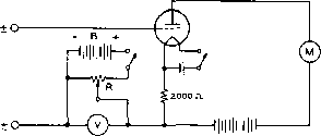 Figure 4 SLIDE-BACK V-T VOLTMETER By connecting a variable source of voltage in series with the input to a conventional v-t voltmeter, or in series with the simple triode voltmeter shown above, a slide-bacic a-c voltmeter for peak voltage measurement con be constructed. Resistor R should be about 1000 ohms per volt used at battery B. This type of v-t voltmeter has the advantage that it can give a reading of the actual peak voltage of the wave being measured, without any current drain from the source of voltage. instrument having an integral copper oxide or selenium rectifier is usually used. Radio frequency voltage measurements are usually made virith some type of vacuum-tube voltmeter, while r-f current measurements are almost invariably made with an instrument containing a thermo-couple to convert the r.f. into d.c. for the movement. Since an alternating current wave can have an almost infinite variety of shapes, it can easily be seen that the ratios between the three fundamental quantities of the wave (peak, r.m.s. effective, and average after rectification) can also vary widely. So it becomes necessary to know beforehand just which quality of the wave under measurement our instrument is going to indicate. For the purpose of simplicity we can list the usual types of a-c meters in a table along with the characteristic of an a-c wave which they will indicate; Iron-vane, thermocouple-r.m.s. Rectifier type (copper oxide or selenium) -average after rectification. V.t.v.m.-r.m.s., average or peak, depending upon design and calibration. Vacuum-Tube A vacuum-tube voltmeter is es-Voltmeters sentially a detector in which a change in the signal placed upon the input will produce a change in the indicating instrument (usually a dArsonval meter) placed in the output circuit. A vacuum-tube voltmeter may use a diode, a triode, or a multi-element tube, and it may be used either for the measurement of a.c, or d.c. When a v.t.v.m. is used in d-c measurement it is used for this purpose primarily because of the very great input resistance of rhe device. This means that a v.t.v.m. may be used for the measurement of a-v-c, a-f-c, and discriminator output voltages where no loading of the circuit can be tolerated. A-C V-T There are many different types Voltmeters of a-c vacuum-tube voltmeters, all of which operate as some type of rectifier to give an indication on a d-c instrument. There are two general types: those which give an indication of the r-m-s value of the wave (or approximately this value of a complex wave), and those which give an indication of the peak or crest value of the wave. Since the setting up and calibration of a wide-range vacuum-tube voltmeter is rather tedious, in most cases it will be best to purchase a commercially manufactured unit. Several excellent commercial units are on the market at the present time; also kits for home construction of a quite satisfactory v.t.v.m. are available from several manufacturers. These feature a wide range of a-c and d-c voltage scales at high sensitivity, and in addition several feature a built-in vacuum-tube ohmmeter which will give indications up to 500 or 1000 megohms. Peak A-C V-T There are two common types Voltmeters of peak-indicating vacuum-tube voltmeters. The first is the so-called slide-back type in which a simple v.t.v.m. is used along with a conventional d-c voltmeter and a source of bucking bias in series with the input. With this type of arrangement (figure 4) leads are connected to the voltage to be measured and the slider resistor R across the bucking voltage is backed down until an indication on the meter (called a false zero) equal to that value given with the prods shorted and the bucking voltage reduced to zero, is obtained. Then the value of the bucking voltage (read on V) is equal to the peak value of the voltage under measurement. The slide-back voltmeter has the disadvantage that it is not instantaneous in its indication-adjustments must be made for every voltage measurement. For this reason the slide-back v.t.v.m. is not commonly used, being supplanted by the diode-rectifier type of peak v.t.v.m. for most applications. High-Voltage A diode vacuum-tube voltmeter Diode Peak suitable for the measurement Voltmeter of high values of a-c voltage is diagrammed in figure 5. With the constants shown, the voltmeter has two 2X2/879 2X2/879 VOLTAGE FROM SOURCE WITH RETURN PATH r©7 Figure 5 SCHEMATIC OF A HIGH-VOLTAGE PEAK VOLTMETER A peak voltmeter such os diagrammed above is convenient for tbe measurement of peak voltages at fairly high power levels from a source of moderately low impedance. Cl-.001-tifd. high-voltage mica Сг-l.Ofifd. high-voltage paper Rl-500,000 ohms (two 0,2S-megohm V2-wait in series) Re-1.0 megohm (four 0.25-megohm Vj-wati in series) J-2.5 v., 7.75 a. filament transformer M-0-1 d-c milliammeter Sj j-S-p-d-t toggle switch S-S-p-s-f toggle switch (Note: Cl is a by-pass around Сг, the inductive reactance of which may be appreciable at high frequencies.) ranges: 500 and 1500 volts peak full scale. Capacitors Ci and Cs should be able to withstand a voltage in excess of the highest peak voltage to be measured. Likewise, Ri and R2 should be able to withstand the same amount of voltage. The easiest and least expensive way of obtaining such resistors is to use several low-voltage resistors in series, as shown in figure 5. Other voltage ranges can be obtained by changing the value of these resistors, but for voltages less than several hundred volts a more linear calibration can be obtained by using a receiving-type diode. A calibration curve should be run to eliminate the appreciable error due to the high internal resistance of the diode, preventing the capacitor from charging to the full peak value of the voltage being measured. A direct reading diode peak voltmeter of the type shown in figure 5 will load the source of voltage by approximately one-half the value of the load resistance in the circuit (Ri, or Ri plus R3, in this case). Also, the peak voltage reading on the meter will be slightly less than the actual peak voltage being measured. The amount of lowering of the reading is determined by the ratio of the reactance of the storage capacitance to the load resistance. If a cathode-ray oscilloscope is placed across the terminals of the v.t.v.m. when a voltage is being measured, the actual amount of the lowering in voltage may be determined by inspection VOLTAGE FROM SOURCE WITH RETURN PATH о о о -о CONVENTIONAL HIGH-SENSITIVITY VOLTMETER Figure 6 PEAK-VOLTAGE MEASUREMENT CIRCUIT Through use of the arrangement shown above it is possible to make accurate measurements of peak a-c voltages, such as across the secondary of a modulation transformer, witfi a conventional d-c multi-voltmeter. Capacitor С and transformer T should, of course, be insulated for the highest peak voltage likely to be encountered. A capacitance of 0.2S-iifd. at С has been found to be adequate. The higher the sensitivity of the indicating d-c voltmeter, the smaller will be the error between the indication on the meter and the actual peak voltage being measured. of the trace on the c-r tube screen. The peak positive excursion of the wave will be slightly flattened by the action of the v.t.v.m. Usually this flattening will be so small as to be negligible. An alternative arrangement, shown in figure 6, is quite convenient for the measurement of high a-c voltages such as are encountered in the adjustment and testing of high-power audio amplifiers and modulators. The arrangement consists simply of a 2X2 rectifier tube and a filter capacitor of perhaps 0.25-/u-fd. capacitance, but with a voltage rating high enough that it is not likely to be punctured as a result of any tests made. Cathode-ray oscilloscope capacitors, and those for electrostatic-deflection TV tubes often have ratings as high as 0.25 /fd. at 7500 to 10,000 volts. The indicating instrument is a conventional multi-scale d-c voltmeter of the high-sensitivity type, preferably with a sensitivity of 20,000 or 50,000 ohms per volt. The higher the sensitivity of the d-c voltmeter used with the rectifier, the smaller will be the amount of flattening of the a-c wave as a result of the rectifier action. Measurement Audio frequency or radio fre-of Power quency power in a resistive circuit is most commonly and most easily determined by the indirect method, i.e., through the use of one of the following formulas: P = EI P = EVR P = TR These three formulas mean that if any two of the three factors determining power are known 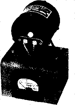 Figure 7 100-WATT DUMMY LOAD SUITABLE FOR RANGER, OR SIMILAR TYPE TRANSMITTER (resistance, current, voltage) the power being dissipated may be determined. In an ordinary 120-volt a-c line circuit the above formulas are not strictly true since the power factor oi the load must be multiplied into the result- or a direct method of determining power such as a wattmeter may be used. But in a resistive a-f circuit and in a resonant r-f circuit the power factor of the load is taken as being unity. For accurate measurement of a-f and r-f power, a thermogalvanometer or thermocouple ammeter in series with a non-inductive resistor of known resistance can be used. The meter should have good accuracy, and the exact value of resistance should be known with accuracy. Suitable dummy load resistors are available in various resistances in both 100 and 250-watt ratings. These are virtually non-inductive, and may be considered as a pure resistance up to 30 iVfc. The resistance of these units is substantially constant for all values of current up to the maximum dissipation rating, but where extreme accuracy is required, a correction chart of the dissipation coefficient of resistance (supplied by the manufacturer) may be employed. This chart shows the exact resistance for different values of current through the resistor. Sine-wave power measurements (r-f or sin-gie-frequency audio) may also be made through the use of a v.tv.m. and a resistor of known value. In fact a v.t.v.m. of the type shown in figure 6 is particularly suited to this work. The formula, P = EVR is used in this case. However, it must be remembered that a v.t.v.m. of the type shown in figure 6 indicates the peak value of the a-c wave. This reading must be converted to the r-m-s or heating value of the wave by multiplying it by 0.707 before substituting the voltage value in the formula. The same result can be obtained by using the formula P = EV2R. Thus all three methods of determining power, ammeter-resistor, voltmeter-resistor, and voltmeter-ammeter, give an excellent crosscheck upon the accuracy of the determination and upon the accuracy of the standards. Power may also be measured through the use of a calorimeter, by actually measuring the amount of heat being dissipated. Through the use of a water-cooled dummy load resistor this method of power output determination is being used by some of the most modern broadcast stations. But the method is too cumbersome for ordinary power determinations. Power may also be determined photometrically through the use of a voltmeter, ammeter, incandescent lamp used as a load resistor, and a photographic exposure meter. With this method the exposure meter is used to determine the relative visual output of the lamp running as a dummy load resistor and of the lamp running from the 120-volt a-c line. A rheostat in series with the lead from the a-c line to the lamp is used to vary its light intensity to the same value (as indicated by the exposure meter) as it was putting out as a dummy load. The a-c voltmeter in parallel with the lamp and ammeter in series with it is then used to determine lamp power input by: P = EI. This method of power determination is satisfactory for audio and low frequency r.f. but is not satisfactory for v-h-f work because of variations in lamp efficiency due to uneven heating of the filament. Dummy Loads Lamp bulbs make poor dummy loads for r-f work, in general, as they have considerable reactance above 2 Mc, and the resistance of tbe lamp varies with the amount of current passing through it. A suitable r-f load for powers up to a few watts may be made by paralleling 2-watt composition resistors of suitable value to make a 50-ohm resistor of 5 or 10 watts dissipation. The resistors should be mounted in a compact bundle, with short interconnecting leads. For powers of 100 and 250 watts, the Ohmite models D-101 and D-251 low inductance resistors may be used as dummy antennas. A D-101 resistor mounted on a small metal chassis with a r-f ammeter and coaxial plug is shown in figure 7. The Ohmite D-250 resistor may be employed in such a configuration for higher power. A dummy load capable of taking the output of a plate-modulated 1-kilowatt transmitter is shown in figure 8. The load is made up of ten 160-watt, 500-ohm Ohmite type 2409 non-inductive resistors. These resistors are mounted between two aluminum end plates measuring 4 Inches In diameter. The assembly is then end mounted by means of 1 ceramic insulators to an aluminum chassis containing the r-f ammeter and an SO-239 coaxial receptacle. This dummy load presents a good approxi-marion of a 50-ohm, l600-watt resistor up to approximately 8 Mc. Above this frequency, it becomes increasingly reactive. It may be used up to 30 Mc, if it is remembered that the reading of the r-f ammeter no longer is an absolute indication of the resistive power dissipation of the load. For use on the 20, 15 and 10 meter bands, it is recommended that the coaxial line coupling the dummy load to the transmitter either be restricted to a length of two feet or less, or else be made an electrical half-wavelength long. This will insure that a minimum of reactance will be coupled back into the transmitter. 34-2 Measurement- of Circuit- Const-anf-s The measurement of the resistance, capacitance, inductance, and Q (figure of merit) of the components used in communications work-can be divided into three general methods: the impedance method, the substitution or resonance method, and the bridge method. The Impedance The impedance method of Method measuring Inductance and capacitance can be likened to the ohmmeter method for measuring resistance. An a-c voltmeter, or milliammeter in series with a resistor, is connected in series with the inductance or capacitance to be measured and the a-c line. The reading of the meter will be inversely proportional to the inipedance of the component being measured. After the meter has been calibrated it will be possible to TRANSMITTER 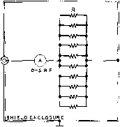 R - TEN 500-OHM, teo-WATT NON-INDUCTIVE RESISTORS IN PARALLEL {OHUITt t<03) Figure 8 1.6-KILOWATT DUMMY LOAD SCHEMATIC obtain the approximate value of the impedance directly from the scale of the meter. If the component Is a capacitor, the value of impedance may be taken as its reactance at the measurement frequency and the capacitance determined accordingly. But the d-c resistance of an Inductor must also be taken Into consideration in determining its inductance. After the d-c resistance and the impedance have been determined, the reactance may be determined from the formula: Xl=VZ ~R. Then the inductance may be determined from: L = XL/27rf. The Substitution The substitution method is Method a satisfactory system for obtaining the inductance or capacitance of high-frequency components. A large variable capacitor with a good dial having an accurate calibration curve is a necessity for making determinations by this method. If an unknown inductor is to be measured, it is connected in parallel with the standard capacitor and the combination tuned accurately to some known frequency. This tuning may be accomplished either by using the tuned circuit as a wavemeter and coupling it to the tuned circuit of a reference oscillator, or by using the tuned circuit in the controlling position of a two terminal oscillator such as a dynatron or transitron. The capacitance required to tune this first frequency is then noted as Ci. The circuit or the oscillator is then tuned to the second harmonic of this first frequency and the amount of capacitance again noted, this time as G. Then the distributed capacitance across rhe coil (including all stray capacitances) is equal to: Co=(G~4G)/3. 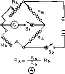 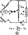 Figure 9 TWO WHEATSTONE BRIDGE CIRCUITS These circuits are used for the measurerrtent of d-c resistance. In (A) the ratio arms Rg end ore fixed and balancing ot the bridge is accomplished by variation of the standard Rg. The standard in this case usually consists of a decade box giving resistance in 1-ohm steps from 0 to 1110 or to 11,110 ohms. In (B) a fixed standard is used for each range end the ratio arm is varied to obtain balance, A calibrated slide-wire or potentiometer calibrated by resistance in terms of degrees is usually employed as and Rg. It will be noticed that the formula for determining ihe unknown resistance from tbe known is the same in either ease. This value of distributed capacitance is then substituted in the following formula along with the value of the standard capacitance for either of the two frequencies of measurement: L =- The determination of an unknown capacitance is somewhat less complicated than the above. A tuned circuit including a coil, the unknown capacitor and the standard capacitor, all in parallel, is resonated to some convenient frequency. The capacitance of the standard capacitor is noted. Then the unknown capacitor is removed and the circuit re-resonated by means of the standard capacitor. The difference between the two readings of the standard capacitor is then equal to the capacitance of the unknown capacitor. 34-3 Measurements with a Bridge Experience has shown that one of the most satisfaaory methods for measuring circuit constants (resistance, capacitance, and inductance) at audio frequencies is by means of the a-c bridge. The Wheatstone {d-c) bridge is also one of the most accurate methods for the measurement of d-c resistance. With a simple bridge of the type shown at figure 9A it is entirely practical to obtain d-c resistance de- terminations accurate to four significant figures. With an a-c bridge operating within its normal rating as to frequency and range of measurement it is possible to obtain results accurate to three significant figures. Both the a-c and the d-c bridges consist of a source of energy, a standard or reference of measurement, a means of balancing this standard against the unknown, and a means of indicating when this balance has been reached. The source of energy in the d-c bridge is a battery; the indicator is a sensitive galvanometer. In the a-c bridge the source of energy is an audio oscillator (usually in the vicinity of 1000 cycles), and the indicator is usually a pair of headphones. The standard for the d-c bridge is a resistance, usually in the form of a decade box. Standards for the a-c bridge can be resistance, capacitance, and inductance in varying forms. Figure 9 shows two general types of the Wheatstone or d-c bridge. In (A) the so-called ratio arms Ra and Rb are fixed (usually in a ratio of 1-to-l, 1-to-lO, 1-to-lOO, or 1-to-1,000) and the standard resistor Rs is varied until the bridge is in balance. In commercially manufactured bridges there are usually two or more buttons on the galvanometer for progressively increasing its sensitivity as balance is approached. Figure 9B is the slide wire type of bridge in which fixed standards are used and the ratio arm is continuously variable. The slide wire may actually consist of a moving contact along a length of wire of uniform cross section in which case the ratio of Ra to Rb may be read off direaly in centimeters or inches, or in degrees of rotation if the slide wire is bent around a circular former. Alternatively, the slide wire may consist of linear-wound potentiometer with its dial calibrated in degrees or in resistance from each end. Figure lOA shows a simple type of a-c bridge for the measurement of capacitance and inductance. It can also, if desired, be used for the measurement of resistance. The four arms of the bridge may be made up in a variety of ways. As before, Rb and Ra make up the ratio arms of the device and may be either of the slide wire type, as indicated, or they may be fixed and a variable standard used to obtain balance. In any case it is always necessary with this type of bridge to use a standard which presents the same type of impedance as the unknown being measured: resistance standard for a resistance measurement, capacitance standard for capacitance, and inductance stand- ard for inductance determination. Also, it is a great tielp in obtaining an accurate balance of the bridge if a standard of approximately the same value as the assumed value of the unknown is employed. Also, the standard should be of rhe same general type and should have approximately the same power factor as the unknown impedance. If all these precautions are observed, little trouble will be experienced in the measurement of resistance and in the measurement of impedances of the values usually used in audio and low radio frequency work. However, the bridge shown at lOA will not be satisfactory for the measurement of capacitances smaller than about 1000 /nfxfd. For the measurement of capacitances from a few micro-microfarads to about 0.001 jufd. a Wagner grounded substitution capacitance bridge of the type shown in figure lOB will be found satisfactory. The ratio arms Ra and Rb should be of the same value within 1 per cent; any value between 2500 and 10,000 ohms for both will be satisfactory. The two resistors Rc and Rd should be 1000-ohm wire-wound potentiometers. Cs should be a straight-line capacitance capacitor with an accurate vernier dial; 500 to 1000 fxjufd. will be satisfactory. Cv can be a two or three gang broadcast capacitor from 700 to 1000 jn/ufd. maximum capacitance. The procedure for making a measurement is as follows: The unknown capacitor Cx is placed in parallel with the standard capacitor Cs. The Wagner ground Rp is varied back and forth a small amount from the center of its range until no signal is heard in the phones with the switch S in the center position. Then the switch S is placed in either of the two outside positions, Cc is adjusted to a capacitance somewhat greater than the assumed value of the unknown Cx, and the bridge is brought into balance by variation of the standard capacitor Cs. It may be necessary to cut some resistance in at Rc and to switch to the other outside position of S before an exact balance can be obtained. The setting of Cs is then noted, Cx is removed from the circuit (but the leads which went to it are not changed in any way which would alter their mutual capacitance), and Cs is readjusted until balance is again obtained. The difference in the two settings of Cm is equal to the capacitance of the unknown capacitor Cx. There are many other types of a-c bridge circuits in common use for measuring inductance with a capacitance standard, frequency 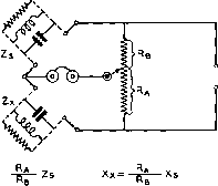 AUDIO OSCILLATOR Zx=IMPEOANCE BEING MEASURED, Rs = RESISTANCE COMPONENT OF Zs Zs= IMPEDANCE OF STANDARD, Xa = REACTANCE COMPONENT OF Zx Rx= RESISTANCE COMPONENT OF Zx, Xs= REACTANCE COMPONENT OF Zs 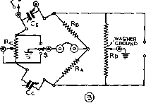 AUDIO OSCILLATOR Figure 10 TWO AC BRIDGE CIRCUITS The operation of these bridges is essentially tbe same as those of figure 9 except that a.c. is fed into the bridge instead of d.c. and a pair of phones is used as the indicator instead of the galvanometer. The bridge shown at (A) can be used for the measurement of resistance, but it is usually used for the measurement of the impedance and reactance of coils and capacitors at frequencies from 200 to 1000 cycles. The bridge shown at (B) is used for tbe measurement of small values of capacitance by the substitution method, full description of the operation of both bridges is given in the accompanying text. in terms of resistance and capacitance, and so forth. Termans Radio Engineers Handbook gives an excellent discussion of common types of a-c bridge circuits. 34-4 Frequency Measurements All frequency measurement within the United States is based on the transmissions of Station WWV of the National Bureau of Standards. This station operates continuously on frequencies of 2.5, 5, 10, 15, 20, 25, 30, and 35 Mc. The carriers of those frequencies below 30 Mc. are modulated alternately by a 440-cycle tone or a 600-cycle tone for periods of four minutes each. This tone is interrupted at the beginning of the 59th minute 6BA6 r-if-° 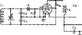 SIGNAL OUT О 63 v.A.c. о + too-EOOV. О GROUND Ci-100-iiiitd. air trimmer C2,C]-O.OOOZ-tifd. midget mica Cj,-SO-niifd. midget mica Cs-0.002-iifd. midget mica Ri, Rb-100,000 ohms /2 watt Li-10-mh, shielded r-f choke Ll-2.1-mh. r-t choke X-lOO-te. crystal Figure 11 SCHEMATIC OF A 100-KC, FREQUENCY SPOTTER of each hour and each five minutes thereafter for a period of precisely one minute. Greenwich Civil Time is given in code during these one-minute intervals, followed by a voice announcement giving Eastern Standard Time. The accuracy of all radio and audio frequencies is better than one part in 50,000,000. A 5000 microsecond pulse (5 cycles of a 1000-cycle wave) may be heard as a tick for every second except the 59th second of each minute. These standard-frequency transmissions of station WWV may be used for accurately determining the limits of the various amateur bands with the aid of the station communications receiver and a 50-kc., lOO-kc, or 200-kc. band-edge spotter. The low frequency oscillator may be self-excited if desired, but low frequency standard crystals have become so relatively inexpensive that a reference crystal may be purchased for very little more than the cost of the components for a self-excited oscillator. The crystal has the additional advantage that it may be once set so that its harmonics are at zero beat with WWV and then left with only an occasional check to see that the frequency has not drifted more than a few cycles. The self-excited oscillator, on the other hand, must be monitored very frequently to insure that it is on frequency. Using о To use a frequency spotter it is Frequency only necessary to couple the out-Spotl-er put of the oscillator unit to the antenna terminal of the receiver through a very small capacitance such as might be made by twisting two pieces of insulated hookup wire together. Station WWV is then tuned in on one of its harmonics, 15 Mc. will usually be best in the daytime and 5 or 10 Mc. at night, and the trimmer adjustment on the oscillator is varied until zero beat is obtained between the harmonic of the oscillator and WWV. With a crystal reference osciUator no difficulty will be had with using the wrong harmonic of the oscillator to obtain the beat, but with a self-excited oscillator it will be wise to insure that the reference oscillator is operating exaaly on 50, 100, or 200 kc. (whichever frequency has been chosen) by making sure that zero beat is obtained simultaneously on all the frequencies of WWV that can be heard, and by noting whether or not the harmonics of the oscillator in the amateur bands fall on the approximate calibration marks of the receiver. A simple frequency spotter is diagrammed in figure 11. 34-5 Antenna and Transmission Line Measurements The degree of adjustment of any ai7iateur antenna can be judged by the study of the standing-wave ratio on the transmission line feeding the antenna. Various types oif 1 nstru-ments have been designed to measure the s.r.w. present on the transmission line, or to measure the actual radiation resistance of the antenna in question. The most important of these instruments are the slotted line, the bridge-type s-w-r meter, and the antennascope. The Slotted Une It is obviously impractical to measure the voltage-standing-wave ratio in a length of coaxial line since the voltages and currents inside the line are completely shielded by the outer conductor of the cable. Hence it is necessary to insert some type of instrument into a section of the line in order to be able to ascertain the conditions which are taking place inside the shielded line. Where measurements of a high degree of accuracy are required, the slotted line is the instrument most frequently used. Such an instrument, diagrammed in figure 12, is an item of test equipment which could be constructed in a home workshop which included a lathe and other metal working tools. 1 ... 70 71 72 73 74 75 76 ... 80 |
|
© 2026 AutoElektrix.ru
Частичное копирование материалов разрешено при условии активной ссылки |