 |
 |
 |
| Главная Журналы Популярное Audi - почему их так назвали? Как появилась марка Bmw? Откуда появился Lexus? Достижения и устремления Mercedes-Benz Первые модели Chevrolet Электромобиль Nissan Leaf |
Главная » Журналы » Simple coaxial reflectometer 1 ... 71 72 73 74 75 76 77 ... 80 ljlgjAPER PROBE INNER CO;gDUCTOR TAPER CARRIER FOR PROBE  V SLOT IN OUTER I SLIDER CONDUCTOR CARRYING PROSE INDICATING INSTRUMENT Figure 12 DIAGRAMMATIC REPRESENTATION OF A SLOTTED LINE The conductor ratios in the slotted line, in-eluding the tapered end sections should be such that the characteristic impedance of the equipment is the some as that of the transmission line with which the equipment is to be used. The indicating instrument may be operated by fhe d-c output of fhe rectifier coupled to the probe, or it may be operated by the o-c components of the rectified signal if the signal generator or transmitter is amplitude modulated by a constant percentage. Commercially built slotted lines are very expensive since they are constructed with a high degree of accuracy for precise laboratory work. The slotted line consists essentially of a section of air-dielectric line having the same charaaeristic impedance as the transmission line into which it is inserted. Tapered fittings for the transmission line connectors at each end of the slotted line usually are required due to differences in the diameters of the slotted line and the line into which it is inserted. A narrow slot from i/g-inch to V4-inch in width is cut into the outer conductor of the line. A probe then is inserted into the slot so that it is coupled to the field inside the line. Some sort of accurately machined track or lead screw must be provided to insure that the probe maintains a constant spacing from the inner conductor as it is moved from one end of the slotted line to the other. The probe usually includes some type of rectifying element whose output is fed to an indicating instrument alongside the slotted line. The unfortunate part of the slotted-line system of measurement is that the line must be somewhat over one-half wavelength long at the test frequency, and for best results should be a full wavelength long. This requirement is easily met at frequencies of 420 Mc. and above where a full wavelength is 28 inches or less. But for the lower frequencies such an instrument is mechanically impracticable. Bridge-Type Standing-Wove Indicators The bridge type of standing-wave indicator is used quhe generally for making measurements on commercial co- r2 4:ci IN34 r4 W-1 Д- TO ANTENNA FEED LINE fo-:oo\  Figure 13 RESISTOR-BRIDGE STANDING-WAVE INDICATOR This type of test equipment is suitable for use with coaxial feed lines. Ci-0.001-iifd. midget ceramic capacitor Cs Cs-.001 disc ceramic Ri, Re-22-ohm 2-wott carbon resistors Rs-Resistor equal in resistance to the characteristic impedance of tbe coaxial transmission line to be used waftj R;,-5000-ohm wire-wound potentiometer Ri-10,000-ohm 1-watt resistor RFC-R-f choke suitable for operation at the measurement frequency axial transmission lines. A simplified version is available from M. C. Jones Electronics Co., Bristol, Conn. ( Micro-Match ). One type of bridge standing-wave indicator is diagrammed in figure 13- This type of instrument compares the electrical impedance of the transmission line with that of the resistor Rs which is included within the unit. Experience with such units has shown that the resistor Rs should be a good grade of non-inductive carbon type. The Ohmite Ltttle Devil type resistor in the 2-watt rating has given good performance. The resistance at Ra should be equal to the characteristic impedance of the antenna transmission line. In other words, this resistor should have a value of 52 ohms for lines having this characteristic impedance such as RG-8/U and RG-58/U. For use with lines having a nominal characteristic impedance of 70 ohms, a selected 68 ohm resistor having an actual resistance of 70 ohms may be used. Balance within the equipment is checked by mounting a resistor, equal in value to the nominal characteristic impedance of the Une to be used, on a coaxial plug of the type used on the end of the antenna feed line. Then this plug is inserted into the input receptacle of the instrument and a power of 2 to 4 watts applied to the output receptacle on the desired frequency of operation. Note that the signal is passed through the bridge in the direction < > о 2 Q 2 <
0 0.1 0,2 0.3 0,4 0.5 06 0.7 0-8 0,9 1.0 READING ON 0-! INSTRUMENT, OR FACTOR TIMES FULL SCALE (MAGNITUDE OF REFLECTION COEFFICIENT, A ) Figure 14 liELATrON BETWEEN STANDING-WAVE RATIO AND REFLECTION COEFFICIENT This chart may be used to convert reflection-coefficient indications such as are obtained with a bridge-type standing-wave indicator or an indicating twin lamp into values of standing-wave ratio. REFLECTOMETER OUTER SHELL INNER CONDUCTOR ¥ -тЛЛЛ- Rz 10 к  FORWARD I POWER REFLECTED] POWER UT, 2 i NDICATOR COMPONENT PARTS EMD DISC = г 3/8 DIAMETER X 1/4 (2 PEO.) CUTE R SHELL = 2 3/8 I.D. X 6 (/ PEQ . J ALIGNMENT ROD= 1/4 DIAMETER X S 1/2 REQ. ) INNER CONDUCTORS 1/2 DIAMETER )( Ъ 1/8 , TAPER ENDS TO SOLDER TO RECEPTACLES [2 REQ.) RECEPTACLES= S0-239 (.2 REQ.) (Ji,j2) BINDING POSTS - iJ RES.) Figure 15 SCHEMATIC, REFLECTOMETER O Dl-Crystal diode, 1N34A or 1Ш2 Rl-370 ohm, I wait composition resistor. IRC type BTA, matched pair. M-0-1 d.c. milliammeter Jl, Jt-Coaxial receptacle, SO-239. opposite to normal for this test. The resistor Ri is adjusted for full-scale deflection on the 0-100 microammeter. Then the plugs are reversed so that the test signal passes through the instrument in the direction indicated by the arrow on figure 13, and the power level is maintained the same as before. If the test resistor is matched to Ra, and stray capacitances have been held to low values, the indication on the milliammeter will be very small. The test plug with its resistor is removed and the plug for the antenna transmission line is inserted. The meter indication now will read the reflertion coefficient which exists on the antenna transmission line at the point where the indicaror has been inserted. From this reading of reflection coefficient the actual stand ing-wave ratio on the transmission line may be determined by reference to the chart of figure 14. Measurements of this type are quite helpful in determining whether or not the antenna is presenting a good impedance match to the transmission line being used to feed it. However, a test instrument of the type shown in figure 13 must be inserted into the line for a measurement, and then removed from the line when the equipment is to be operated. Also, the power input to the line feeding the input terminal of the standing-wave indicator must not exceed 4 warts. The power level which the unit can accept is determined by the dissipation limitation of resistors Ri plus Ra. It is also important, for satisfactory operation of the test unit, that resistors Ri and Ra be exactly equal in value. The actual resistance of these two is not critically important, and deviations up to 10 per cent from the value given in figure 13 will be satisfactory. But the two resistors must have the same value, whether they are both 21 ohms or 24 ohms, or some value in between. 34-6 A Simple Coaxial Reflectometer The reflectometer is a short section of coaxial transmission line containing two r-f voltmeters. One voltmeter reads the incident component of voltage in the line, and the orher HANDBOOK Reflectometer 733   Figure 16 INTERIOR VIEW OF COAXIAL REFLECTOMETER The Reflectometer is a siiort section of transmission Ime containing two r-f voltmeters. Center conductor of line is a section of bross rod soldered to center pins of input Ond output receptacles. At either end of unit are the crystal diodes, bypass capaciiors and terminals. Diode load resistors are at center of instrument, grounded to brass alignment rod. reads the reflected component. The magnitude of standing wave ratio on the transmission hne is the ratio of the incident component to the reflected component, as shown in figure 14. In actual use, calibration of the reflectometer is not required since the relative reading of reflected power indicates the degree of match or mis-match and all antenna and transmission line adjustments should be conducted so as to make this reading as low as possible, regardless of its absolute value. The actual meter readings obtained from the device are a function of the operating frequency, the sensitivity of the instrument being a function of transmitter power, increasing rapidly as the frequency of operation is increased. However, the reflectometer is invaluable in that it may be left permanently in the transmission line, regardless of the power output level of the transmitter. It will indicate the degree of reflected power in the antenna system, and at the same time provide a visual indication of the power output of the transmitter. Reflectometer The circuit and assembly in-Circuit formation for the reflectometer are given in figure 15. Two diode voltmeters are coupled back-to-back to a short length of transmission line. The combined inductive and capacative pickup between each voltmeter and the line is such that the incident component of the line voltage is balanced out in one case and the inductive component is balanced out in the other case. Each voltmeter, therefore, reads only one wave-com- ponent. Careful attention to physical symmetry of the assembly insures accurate and complete separation of the voltage components by the two voltmeters. The outputs of the two voltmeters may be selected and read on an external meter connected to the terminal posts of the reflectometer. Each r-f voltmeter is composed of a load resistor and a pickup loop. The pickup loop is positioned parallel to a section of transmission line permitting both inductive and capacative coupling to exist between the center conductor of the line and the loop. The dimensions of the center conduaor and the outer shield of the reflectometer are chosen so that the instrument impedance closely matches that of the transmission line. Reflectometer A view of the interior of the Construction reflectometer is shown in figure 16. The coaxial input and output connectors of the instrument are mounted on machined brass discs that are held in place by brass alignment rods, tapped at each end. The center conductor is machined from a short section of brass rod, tapered and drilled at each end to fit over the center pin of each coaxial receptacle. The end discs, the rods, and the center conductor should be silver plated before assembly. When the center conductor is placed in position, it is soldered at each end to the center pin of the coaxial receptacles. One of the alignment rods is drilled and tapped for a 6-32 bolt at the mid-point, and the end discs are drilled to hold 1/2-inch ceramic insulators and binding posts, as shown in the photograph. The load resistors, crystal diodes, and bypass capacitors are finally mounted in the assembly as the last step. The two load resistors should be measured on an ohmmeter to ensure that the resistance values are equal. The exact value of resistance is unimportant as long as the two resistors are equal. The diodes should also be checked on an ohmmeter to make sure that the front resistances and back resistances are balanced between the units. Care should be taken during soldering to ensure the diodes and resistors are not overheated. Observe that the resistor leads are of equal length and that each half of the assembly is a mirror-image of the other half. The body of the resistor is spaced about 1/8-inch away from the center conductor. Testing the The instrument can be ad-Reflectometer justed on the 28 Mc. band. An r-f source of a few watts and nonreactive load are required. The construction of the reflectometer is such that it will work well with either 52- or 72-ohm coaxial transmission lines. A suitable dummy load for the 52-ohm line can be made of four 220 ohm, 2 watt composition resistors {Ohmite Little Devil ) connected in parallel. Clip the leads of the resistors short and mount them on a coaxial plug. This assembly provides an eight watt, 55 ohm load, suitable for use at 30 Mc. If an accurate ohmmeter is at hand, the resistors may be hand picked to obtain four 208 ohm units, thus making the dummy load resistors exactly 52 ohms. For all practical purposes, the 55 ohm load is satisfactory. A 75 ohm, eight watt load resistor may be made of four 300 ohm, 2 watt composition resistors conneaed in parallel. R-f power is coupled to the reflectometer and the dummy load is placed in the output receptacle. The indicator meter is switched to the reflected power position. The meter reading should be almost zero. It may be brought to zero by removing the case of the instrument and adjusting the position of the load resistor. The actual length of wire in the resistor lead and its positioning determine the meter null. Replace the case before power is applied to the reflectometer. The reflectometer is now reversed and power is applied to the output receptacle, with a dummy load attached to the input receptacle. The second voltmeter (forward power) is adjusted for a null reading of the meter in the same manner. If a reflected reading of zero is not obtainable, the harmonic content of the r-f source might be causing a slight residual meter reading. Coupling the reflectometer to the r-f source through a tuned circuit ( antenna tuner ) will remove the offending harmonic and permit an accurate null indication. Be sure to hold the r-f input power to a low value to prevent overheating the dummy load resistors. Using the The bridge may be used up to Reflectometer 150 Mc. It is placed in the transmission line at a convenient point, preferably before any tuner, balun, or TVI filter. The indicator should be set to read forward power, with a maximum of resistance in the circuit. Power is applied and the indicator resistor is adjusted for a full scale reading. The switch is then thrown to read reflected power (indicated as A, figure I4). Assume that the forward power meter reading is 1.0 and the reflected power reading is 0.5. Substituting these values in the SWR formula of figure 14 shows the SWR to be 3. If forward power is always set to 1.0 on the meter, the reflected power (A) can be read directly from the curve of figure 14 with little error. If the meter is adjusted so as to provide a half-scale reading of the forward power, the reflectometer may be used as a transmitter power output meter. Tuning adjustments may then be undertaken to provide greatest meter reading. 34-7 Measurements on Balanced Transmission Lines Measurements made on balanced transmission lines may be conducted in the same manner as those made on coaxial lines. In the case of the coaxial lines, care must be taken to prevent flow of r-f current on the outer surface of the line as this unwanted component will introduce errors in measurements made on the line. In like fashion, the currents in a balanced transmission line must be ISO degrees out of phase and balanced with respect to ground in order to obtain a realistic relationship between incident and reflected power. This situation is not always easy to obtain in practice because of the proximity effects of metallic objects or the earth to the transmission line. All transmission line measurements, therefore, should be conducted with the realization of the physical limitations 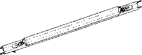 1Ф t -twin LEAD TRANSMISSION LINE TO ANTENNA Figure 17 SKETCH OF THE TWIN-LAMP TYPE OF S-W-R INDICATOR The short sect/on of line with lamps at each end usually is taped to the main transmission line with plastic electrical tape. of the equipment and the measuring technique that is being used. Measurements on One of the most satisfaaory Molded Parallel- and least expensive devices Wire Lines for obtaining a rough idea of the standing-wave ratio on a transmission line of the molded parallel-wire type is the twin-lamp. This ingenious instrument may be constructed of new components for a total cost of about 25 cents; this faa alone places the twin-lamp in a class by itself as far as test instruments are concerned. Figure 17 shows a sketch of a twin-lamp indicator. The indicating portion of the system consists merely of a length of 300-ohm Twin-Lead about 10 inches long with a dial lamp at each end. In the unit illustrated the dial lamps are standard 6.3-volt 150-ma. bayonet-base lamps. The lamps are soldered to the two leads at each end of the short section of Twin-Lead. To make a measurement the short section of line with the lamps at each end is merely taped to the section of Twin-Lead (or other similar transmission line) running from the transmitter or from the antenna changeover relay to the antenna system. When there are no standing waves on the antenna transmission line the lamp toward the transmitter will light while the one toward the antenna will not light. With 300-ohm Twin-Lead running from the antenna changeover relay to the antenna, and with about 200 watts input on the 28-Mc. band, the dial lamp toward the transmitter will light nearly to full briUiancy. With a standing-wave ratio of about 1.5 to 1 on the transmission line to the antenna the lamp toward the antenna will just begin to light. With a high standing-wave ratio on the antenna feed line both lamps will light nearly to full brilliancy. Hence the instrument gives an indication of relatively low standing waves, but when the Figure 18 OPERATION OF THE TWIN LAMP INDICATOR Showing current flow resulting from inductive and capacitive fields in a twin lamp attached to a line with a low standing-wave ratio. Standing-wave ratio is high the twin-lamp merely indicates that they are high without giving any idea of the actual magnitude. Operation of The twin lamp operates by the Twin-Lamp virtue of the fact that the capacitive and inductive couphng of the wire making up one side of the twin-lamp is much greater to the transmission-line lead immediately adjacent to it than to the transmission-line lead on the other side. The same is of course true of the wire on rhe other side of the twin-lamp and the transmission-line lead adjacent to it. A further condition which must be met for the twin-lamp to operate is that the section of line making up the twin-lamp must be short with respect to a quarter wavelength. Then the current due to capacitive coupling passes through both lamps in the same direction, while the current due to inductive couphng between the leads of the twin-lamp and the leads of the antenna transmission line passes through the two lamps in opposite directions. Hence, in a line without reflections, the two currents will cancel in one lamp while the other lamp is lighted due to the sum of the currents (figure 18). The basic fact which makes the twin-lamp a directional coupler is a result of the condition whereby the capacitive coupling is a scalar action not dependent upon the direction of the waves passing down the line, yet the inductive coupling is a vector action which is dependent upon the direction of wave propagation down the line. Thus the capacitive current is the same and is in the same phase for energy travelhng in either direction down the line. But the inductive current travels in one direction for energy travelling in one direction and in the other direaion for energy going the other direction. Hence the two currents add at one end of the line for a wave passing toward the antenna, while the currents add at the other end of the twin-lamp for the waves reflected from the antenna. When the waves are 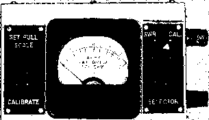 strongly reflected upon reaching the antenna, the reflected wave is nearly the same as the direct wave, and both lamps will light. This condition of strong reflection from the antenna system is that which results in a high stand-irig-wave ratio on the antenna feed line. Use of the Twin Lamp with Various Feed Lines The twin-lamp is best suited for use with antenna transmission lines of the flat ribbon type. Lines with a high power rating are available in impedances of 75 ohms, 205 ohms, and 300 ohms in the flat ribbon type. In addition, one manufacturer makes a 300-ohm line in two power-level ratings with a tubular cross section. A twin-lamp made from flat 300-ohm line may be used with this tubular line by taping the twin-lamp tightly to the mbular line so that the conduaors of the twin-lamp are as close as possible on each side of the conductors of the antenna line. 34-8 A Balanced SWR Bridge Two resistor-type standing wave indicators may be placed back-to-back to form a SWR bridge capable of being used on two wire balanced transmission lines. Such a bridge is shown in figures 19 and 21. The schematic of such an instrument (figure 20) may be compared to two of the simple bridges shown in figure 13. When the dual bridge circuit is balanced the meter reading is zero. This state is reached when the line currents are equal and exactly 180 degrees out of phase and the SWR is unity. As the condition of the line departs from the optimum, the meter of the bridge will Figure 19 SWR BRIDGE FOR BALANCED TRANSMISSION LINE A double bridge can be used for two wire transmission lines. Bridge is inserted in line and may be driven with grid-dip oscillator or other low power r-f source. show the degree of departure. When the line currents are balanced and 180 degrees out of phase, the meter will read the true value of standing wave ratio on the line. If these conditions are not met, the reading is not absolute, merely giving an indication of the degree of mis-match in the line. This handicap is not important, since the relative, not the absolute, degree of mis-match is sufficient for transmission line adjustments to be made. Bridge A suggested method of con- Construction struction of the balanced bridge is illustrated in figures 19 and 21. The unit is constructed within a box measuring 4 X 6 x 2 in size. The 0 - 200 d.c. microammeter is placed in the center of the 4 X 6 side of the case. The input and output connectors of the instrument are placed on each end of the box and the internal wiring is arranged so that the transmission line, in effea, passes in one side of the box and out the other with as little discontinuity as possible. The input and output terminals are mounted on phenolic plates placed over large cutouts in the ends of the box, thus reducing circuit capacity to ground to a minimum value. The SWR-CAL switch St is located on one side of the meter and the Calibrate potentiometer Rl is placed on the opposite side. The transmission line within the unit is 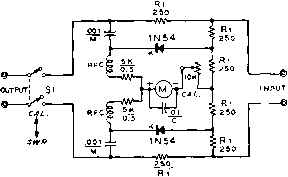 Figure 20 SCHEMATIC OF BRIDGE FOR BALANCED LINES M-0-200 d-c microammeter Rj-Hote: Six 250 ohm resistors are composition, non-inductive units. IRC type ВТ, or Ohmite Little Devil 1-watt resistors may be used, (see text) Si-DPDT rotary switch, Centralab type 1464 Figure 21 INTERIOR VIEW OF BALANCED BRIDGE SHOWING PARTS PLACEMENT Diode rectifiers are placed at right angles to the short section of transmission /ine. Both sides of bridge are balanced to ground by virtue of symmetrical construction ot unj(. 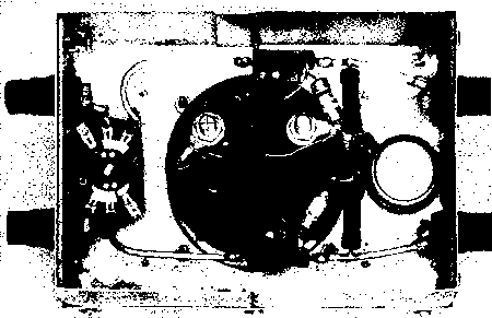 broken by two 250 ohm composition resistors and switch Si. The line segments are made of short pieces of #10 copper wire, running between the various components. Spacing between the wires is held close to three inches to approximate a 500-600 ohm Hne. The small components of the bridge are placed symmetrically about the 250 ohm series line resistors and the calibrating potentiometer, as can be seen in figure 21. Exact parts placement is not critical, except that the crystal diodes should be placed at right angles to the wires of the transmission line to reduce capacative pickup. The two r-f chokes should then be placed at right angles to the diodes. The six 250 ohm resistors are checked on an ohmmeter and should be hand-picked to obtain units that are reasonably close in value. If it is desired to use the bridge with a 600 ohm line, the value of these resistors should be increased to 300 ohms each. Excessive heat should not be used in soldering either the resistors or the diodes to ensure that their characteristics will not be altered by application of high temperatures over an extended period. Testing the Bolanced Bridge When the instrument is completed, a grid-dip meter may be coupled to the input terminals via a two turn hnk. Be careful not to pin the bridge meter. Place switch Si In the Calibrate (open) position. Set the grid dip meter in the 10-Mc. to 20-Mc. range and adjust the hnk and cahbration control Ri for full scale meter reading. A 500 ohm carbon resistor placed across the output terminals of the unit should produce a zero meter reading when Sl is set to the SWR position. Various values of resistance may now be placed across the meter terminals to obtain calibration points for the meter scale. The ratio of the external resistor to the design value of the bridge will provide the SWR value for any given meter reading. For example, a 1000 ohm resistor has a ratio of 1000/500, and will give an indicated SWR reading of 2. A 1500 ohm resistor will give an indicated reading of 3, a 2000 ohm resistor will provide a reading of 4, and so on. Before each measurement is recorded, the calibrate control should be set to a full scale reading with Si open. This simple system of calibration will lead to slight errors in calibration if the regulation of the r-f source is poor. Thar is, a change in the external calibrating resistance will produce a varying load on the r-f generator which could easily cause a change in the power applied to the bridge. A separate diode r-f voltmeter placed across the pickup loop will enable the input voltage to be held to a constant value and will provide somewhat more accurate bridge cahbration. Using the The bridge is placed In the trans-Bridge mission line and driven from a low powered source having a minimum of harmonic content. Several measurements should be made at various frequencies within the range of antenna operation. The selector swirch is set to the Cal. position and the Calibrate potentiometer is adjusted for full scale meter reading. The switch is then set to the SWR position and a reading is taken. This reading and others taken at various frequencies may be plotted on a graph to provide a SWR curve for the particular antenna and transmission line. Antenna adjustments and line balancing operations may now be conducted to provide a smooth SWR curve. г  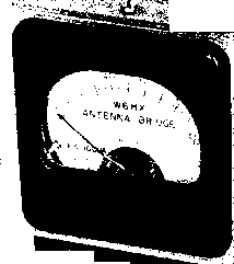 f tJ 5 g  Figure 22 THE ANTENNASCOPE The radiation resistance of r-f loads connected across the output receptacle may be quickly determined by a direct dial reading. The Antennascope may be driven with a grid-dip oscillator, covering r-f impedance range of 5 to IOOO ohms. with the point of minimum SWR occuring at the chosen design frequency of the antenna installation. The complete adjustment and checkout procedure for an antenna and transmission line system is covered in the Beam Antenna Handbook, published by Radio Publications, Inc., Wilton, Conn. 34-9 The Antennascope The Antennascope is a modified SWR bridge in which one leg of the bridge is composed of a non-inductive variable resistor. This resistor is calibrated in ohms, and when its setting is equal to the radiation resistance of the antenna under test the bridge is in a balanced state. If a sensitive voltmeter is con- с hN34l 50 r2 1000 Figure 23 SCHEMATIC, ANTENNASCOPE Rl-rooo ohm composition potentiometer ohmite type AB or Allen Bradley type J, linear taper Rl-50 ohm, 1-watt composition resistor, IRC type ВТ, or ohmite Little Devil (see text) M-0-200 d-c microammeter nected across the bridge, it will indicate a voltage null at bridge balance. The radiation resistance of the antenna may then be read directly from the calibrated resistor of the instrument. When the antenna under test is in a non-resonant or reactive state, the null indication on the meter of the Antennascope will be incomplete. The frequency of the exciting signal must then be moved to the resonant frequency of the antenna to obtain accurate readings of radiation resistance from the dial of the instrument. A typical Antennascope is shown in figures 22 and 24, and the schematic is shown in figure 23. A IOOO ohm non-inductive carbon potentiometer serves as the variable leg of the bridge. The other legs are composed of the 50 ohm composition resistor and the radiation resistance of the antenna. If the radiation resistance of the external load or antenna is 50 ohms and the potentiometer is set at mid-scale the bridge is in balance and the diode voltmeter will read zero. If the radiation resistance of the antenna is any value other than 50 ohms, the bridge may be balanced to this new value by varying the position of the potentiometer. Bridge balance may be obtained with non-reactive loads in the range of 5 ohms to 1000 ohms with this simple circuit. When measurements are conducted at the resonant frequency of the antenna system the radiation resistance of the installation may be read directly from the calibrated dial of the Antennascope. Conversely, a null reading of the instrument will occur at the resonant frequency, which may easily be found with the aid of a calibrated receiver or frequency meter. HANDBOOK Antennascope 739 Constructing the The Antennascope is built Antennascope within a sheet metal case measurmg 3 x 6 x 2 . The indicating meter is placed at the top of the case, and the r-f bridge occupies the lower portion of the box. The input and output coaxial fittings are mounted on each side of the box and the non-inductive 50 ohm resistor is soldered between the center terminals of the receptacles. The calibrating potentiometer (Ri) is mounted upon a phenolic plate placed over a 3y4-inch hole driUed In the front of the box. This reduces the capacity to ground of the potentiometer to a minimum. Placement of the small components within the box may be seen in figure 24. Care should be taken to mount the crystal diode at right angles to the 50 ohm resistor to reduce capacity coupling between the components. The upper frequency limit of accuracy of the Antennascope Is determined by the assembly technique. The unit shown will work with good accuracy to approximately 100 Mc. Above this frequency, the self-inductance of the leads prevents a perfect null from being obtained. For operation in the VHF region, it would be wise to rearrange the components to reduce lead length to an absolute minimum, and to use i-inch copper strap for the r-f leads instead of wire. Testing the When the instrument is com-Antennascope pleted, a grid-dip meter may be coupled to the input receptacle of the Antennascope by means of a two turn link. The frequency of excitation should be in the 10 Mc.-20 Mc. region. Coupling should be adjusted to obtain a half-scale reading of the meter. Various values of 1-watt composition resistors up to 1000 ohms are then plugged Into the output coaxial receptacle and the potentiometer is adjusted for a null on the meter. The settings of the potentiometer may now be calibrated in terms of the load resistor, the null position indicating the value of the test resistor. A calibrated scale for the potentiometer should be made, as shown in figure 22. Using the The antennascope may be Antennascope driven by a grid-dip oscillator coupled to it by a two turn link. Enough coupling should be used to obtain at least a % scale reading on the meter of the Antennascope with no load connected to the measuring terminals. The Antennascope may be considered to be a low range r-f ohm- 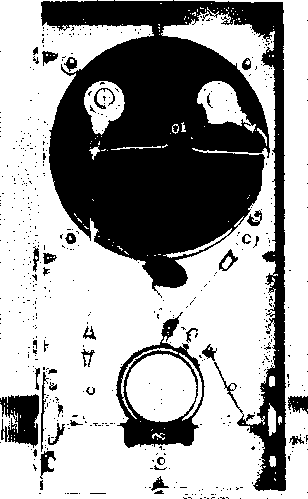 Figure 24 PLACEMENT OF PARTS WITHIN THE ANTENNASCOPE With the length of leads shown this model is useful up to about IOO Mc. Crystal diode should be placed at right angles to 50 ohm composition resistor. meter and may be employed to determine the electrical length of quarter-wave lines, surge impedance of transmission lines, and antenna resonance and radiation resistance. In general, the measuring terminals of the Antennascope are connected in series with the load at a point of maximum cunrent. This means the center of a dipole, or the base of a vertical 1/4-wave ground plane antenna. Excitation is supplied to the Antennascope, and the frequency of excitation and the resistance control of the Antennascope are both varied until a complete null is obtained on the indicating meter of the Antennascope. The frequency of  Figure 25 SIMPLE SILICON CRYSTAL NOISE GENERATOR the source of excitation is now the resonant frequency of the load, and the radiation resistance of the load may be read upon the dial of the Antennascope. On measurements on 80 and 40 meters, it might be found that it is impossible to obtain a complete null on the Antennascope. This is usually caused by pickup of a nearby broadcast station, the rectified signal of the broadcast station obscuring the null indication on the Antennascope. This action is only noticed when antennas of large size are being checked. 34-10 A Silicon Crystal Noise Generator The limiting factor in signal reception above 25 Mc. is usually the thermal noise generated in the receiver. At any frequency, however, the tuned circuits of the receiver must be accurately aligned for best signal-to-noise ratio. Circuit changes (and even alignment changes) in the r-f stages of a receiver may do much to either enhance or degrade the noise figure of the receiver. It is exceedingly hard to determine whether changes of either alignment or circMtry are really providing a boost in signal-to-noise ratio of the receiver, or are merely increasing the gain (and noise) of the unit. 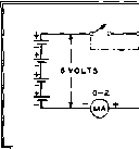 1N2I <=:lb- C.001 CERAMIC SMIELDEP EWCLO U e  A SILICON CRYSTAL NOISE GENERATOR Figure 26 A simple means of determining the degree of actual sensitivity of a receiver is to inject a minute signal in the input circuit and then measure the amount of this signal that is needed to overcome the inherent receiver noise. The less injected signal needed to override the receiver noise by a certain, fixed amount, the more sensitive is the receiver. A simple source of minute signal may be obtained from a silicon crystal diode. If a small d-c current is passed through a silicon crystal in the direction of highest resistance, a small but constant r-f noise (or hiss) is generated. The voltage necessary to generate this noise may be obtained from a few flashlight cells. The generator is a broad band device and requires no mning. If built with short leads, it may be employed for receiver measurements well above 150 Mc. The noise generator should be used for comparative measurements only, since calibration against a high quality commercial noise generator is necessary for absolute measurements. A Practical Shown in figure 25 is a sim- Noise Generator pie silicon crystal noise generator The schematic of this unit is illustrated in figure 26. The 1N21 crystal and .001 /ifd. ceramic capacitor are connected in series directly across the output terminals of the instrument. Three small flashlight batteries are wired in series and mounted inside the case, along with the 0-2 d-c milliammeter and the noise level potentiometer. To prevent heat damage to the 1N21 crystal during the soldering process, the crystal should be held with a damp rag, and the connections soldered to it quickly with a very hot iron. Across the terminals (and in parallel with the equipment to be attached to the generator) is a 1-watt carbon resistor whose resistance is equal to the impedance level at which measurements are to be made. This will usually be either 50 or 300 ohms. If the noise generator is to be used at one impedance level only, this 1 ... 71 72 73 74 75 76 77 ... 80 |
|||||||||||||||||||||||||||||||||||||||||||||||||||||||||||||||||||||||||||||||||||||||||||||||||||||||||||||||||||||||||||||||||||||||||||||||||||||||||||||||||||||||||||||||||||||||||||||||||||||||||||||||||
|
© 2026 AutoElektrix.ru
Частичное копирование материалов разрешено при условии активной ссылки |