 |
 |
 |
| Главная Журналы Популярное Audi - почему их так назвали? Как появилась марка Bmw? Откуда появился Lexus? Достижения и устремления Mercedes-Benz Первые модели Chevrolet Электромобиль Nissan Leaf |
Главная » Журналы » Metal oxide semiconductor 1 ... 12 13 14 15 16 17 18 ... 91 where V is the effective (rms) value of the ac component of load voltage Vi, (10.24) Substituting Eq. (10.24) into Eq. (10.23), the ripple factor can be expressed as  -1 = y/vv RF = In the case of a half-wave rectifier. Half-wave RF = Vl.572 - 1 = 1.21 In the case of a full-wave rectifier. Full-wave RF = Vl.ll - 1 = 0.482 (10.25) (10.26) (10.27) 10.2.3.6 Transformer Utilization Factor The transformer utilization factor (TUF), which is a measure of the merit of a rectifier circuit, is defined as the ratio of the dc output power to the transformer volt-ampere (VA) rating required by the secondary winding. TUF = £dc (10.28) where and are the rms voltage and rms current ratings of the transformer secondary s= = 0.707 (10.29) The rms value of the transformer secondary current is the same as that for the load current 4. For a half-wave rectifier, can be found from Eq. (10.14) Half-wave L = (10.30) For a full-wave rectifier, is found from Eq. (10.16). 0.707 Full-wave L = (10.31) Therefore, the TUF of a half-wave rectifier can be obtained by substituting Eqs. (10.3), (10.13), (10.29), and (10.30) into Eq. (10.28). Half-wave TUF = 0.318 0.707 X 0.5 = 0.286 (10.32) The poor TUF of a half-wave rectifier signifies that the transformer employed must have a 3.496 (1/0.286) VA rating in order to deliver 1W dc output power to the load. In addition, the transformer secondary winding has to carry a dc current that may cause magnetic core saturation. As a result, half-wave rectifiers are used only when the current requirement is small. In the case of a full-wave rectifier with a center-tapped transformer, the circuit can be treated as two half-wave rectifiers operating together. Therefore, the transformer secondary VA rating УД is double that of a half-wave rectifier, but the output dc power is increased by a factor of four due to the higher rectification ratio as indicated by Eqs. (10.5) and (10.15). Therefore, the TUF of a full-wave rectifier with center-tapped transformer can be found from Eq. (10.32) Full-wave TUF = 4 X 0.318 2 X 0.707 X 0.5 = 0.572 (10.33) The bridge rectifier has the highest TUF in single-phase rectifier circuits because the currents flowing in both the primary and secondary windings are continuous sinewaves. By substituting Eqs. (10.5), (10.15), (10.29), and (10.31) into Eq. (10.28), the TUF of a bridge rectifier can be found Bridge TUF = 0.636 0.707 X 0.707 = 0.81 (10.34) The transformer primary VA rating of a full-wave rectifier is equal to that of a bridge rectifier because the current flowing in the primary winding is also a continuous sinewave. 10.2.3.7 Harmonics Full-wave rectifier circuits with resistive load do not produce harmonic currents in their transformers but they are produced in half-wave rectifiers. The amplitudes of the harmonic currents of a half-wave rectifier with resistive load, relative to the fundamental, are given in Table 10.1. The extra loss caused by the harmonics in the resistively loaded rectifier circuits is often neglected because it is not high compared with other losses. However, with nonlinear loads, harmonics can cause appreciable loss and other problems such as poor power factor and interference. TABLE 10.1 Harmonic percentages of a half-wave rectifier with resistive load
TABLE 10.2 Important design parameters of basic single-phase rectifier circuits with resistive load
10.2.4 Design Considerations The goal in practical design is to achieve a given dc output voltage. Therefore, it is more convenient to put aU the design parameters in terms of V. For example, the rating and turns ratio of the transformer in a rectifier circuit can be easily determined if the rms input voltage to the rectifier is in terms of the required output voltage V. Denote the rms value of the input voltage to the rectifier as V, which is equal to 0.707 V. Based on this relation and Eq. (10.3), the rms input voltage to a half-wave rectifier is found as Half-wave V, = 2.22 V, (10.35) Similarly, from Eqs. (10.5) and (10.29), the rms input voltage per secondary winding of a fuU-wave rectifier is found as FuU-wave у = 1.11 V: Another important design parameter is the Peak Repetitive Reverse Voltage (Vrrm) rating of the diodes employed. In the case of a half-wave rectifier, from Eq. (10.3), Half-wave Vrrm = m= = 3.14 V (10.37) In the case of a fuU-wave rectifier with center-tapped transformer, from Eq. (10.5), Full-wave Vy, = 2 V = 2 = 3.14 V (10.38) In the case of a bridge rectifier, also from Eq. (10.5), Bridge V = V== 1.57 уас (10.39) It is important to evaluate the Peak Repetitive Forward Current (4rm) rating of the employed diodes in rectifier circuits. In the case of a half-wave rectifier, from Eq. (10.13), Half-wave /ркм = = = 3.41/, R 0.318 (10.40) In the case of fuU-wave rectifiers, from Eq. (10.15), FuU-wave = = = 1.57/, (10.41) The important design parameters of basic single-phase rectifier circuits with resistive loads are summarized in Table 10.2. (10.36) 10.3 Three-Phase Diode Rectifiers In Section 10.2 we showed that single-phase diode rectifiers require a rather high transformer VA rating for a given dc output power. Therefore, these rectifiers are suitable only for low to medium power applications. For power output higher than 15kW, three-phase or polyphase diode rectifiers should be employed. There are two types of three-phase diode rectifier that convert a three-phase ac supply into a dc voltage, star rectifiers and bridge rectifiers. In the foUowing, the operations of these rectifiers are examined and their performances are analyzed and compared in a table. For the sake of simplicity, the diodes and transformers are considered to be ideal, that is, the diodes have zero forward voltage drop and reverse current, and the transformers do not possess either resistance or leakage inductance. Furthermore, it is assumed that the load is purely resistive, such that the load voltage and the load current have simUar waveforms. The effects of inductive load and capacitive load on a diode rectifier are considered in detaU in Section 10.5. 10.3.1 Three-Phase Star Rectifiers 10.3.1.1 Basic Three-Phase Star Rectifier Circuit A basic three-phase star rectifier circuit is shown in Fig. 10.7. This circuit can be considered as three single-phase half-wave rectifiers combined together. Therefore, it is sometimes referred to as a three-phase half-wave rectifier. The diode in a particular phase conducts during the period when the voltage on that phase is higher than that on the other two phases. The voltage waveforms of each phase and the load are shown in Fig. 10.8. It is clear that, unhke the single-phase rectifier circuit, the conduction angle of each diode is 2я/3, instead of n. This circuit finds uses where the required dc output voltage is relatively low and the required output current is too large for a practical single-phase system. Taking phase R as an example, diode D conducts from n/6 to 5я/6. Therefore, by using Eq. (10.1) the average value of the output can be found as 57Г/6 sine do (10.42) Vdc = m--= 0.827 n 2 (10.43) Similarly, using Eq. (10.6), the rms value of the output voltage can be found as  57Г/6 (ysin) (10.44)  = 0.84 y (10.45) In addition, the rms current in each transformer secondary winding can also be found as L = l  = 0.485 L (10.46) where = VJR. Based on the relationships stated in Eqs. (10.43), (10.45) and (10.46), all the important design parameters of the three-phase star rectifier can be evaluated as listed in Table 10.3. Note that, as with a single-phase half-wave rectifier, the three-phase star rectifier shown in Fig. 10.7 has direct currents in the secondary windings that can cause a transformer core saturation problem. In addition, the currents in the primary do not 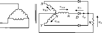 FIGURE 10.7 Three-phase star rectifier. sum to zero. Therefore, it is preferable not to have star-connected primary windings. 10.3.1.2 Three-Phase Inter-Star Rectifier Circuit The transformer core saturation problem in the three-phase star rectifier can be avoided by a special arrangement in its secondary windings, known as zig-zag connection. The modified circuit is called the three-phase interstar or zig-zag rectifier circuit, as shown in Fig. 10.9. Each secondary phase voltage is obtained from two equal-voltage secondary windings (with a phase displacement of я/3) connected in series so that the dc magnetizing forces due to the two secondary windings on any limb are equal and opposite. At the expense of extra secondary windings (increasing the transformer secondary rating factor from 1.51 VA/W to 1.74 VA/W), this circuit connection ehminates the effects of core saturation and reduces the transformer primary rating factor to the minimum of 1.05 VA/W. Apart from transformer ratings, all the design parameters of this circuit are the same as those of a three-phase star rectifier (therefore, they are not separately listed in RN YN 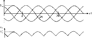 -1.73K
FIGURE 10.8 Waveforms of voltage and current of the three-phase star rectifier as shown in Fig. 10.7. TABLE 10.3 Important design parameters of three-phase rectifier circuits with resistive load Three-Phase Star Rectifier Three-Phase Double-Star Rectifier With Inter-Phase Transformer Three-Phase Bridge Rectifier
  FIGURE 10.9 Three-phase inter-star rectifier. Table 10.3). Furthermore, a star-connected primary winding with no neutral connection is equally permissible because the sum of aU primary phase currents is zero at aU times. 10.3.1.3 Three-Phase Double-Star Rectifier with Interphase Transformer This circuit consists essentially of two three-phase star rectifiers with their neutral points interconnected through an interphase transformer or reactor. The polarities of the corresponding secondary windings in the two interconnected systems are reversed with respect to each other, so that the rectifier output voltage of one three-phase unit is at a minimum when the rectifier output voltage of the other unit is at a maximum as shown in Fig. 10.10. The interphase transformer causes the output voltage to be the average of the rectified voltages Vi and V2 as shown in Fig. 10.11. In addition, the ripple frequency of the output voltage is now six times that of the mains and, therefore, the component size of the filter (if there is any) becomes smaUer. In a balanced circuit, the output currents of two three-phase units flowing in opposite directions in the interphase transformer winding wiU produce no dc magnetization current. SimUarly, the dc magnetization currents in the secondary windings of two three-phase units cancel each other out. By virtue of the symmetry of the secondary circuits, the three primary currents add up to zero  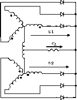 FIGURE 10.10 Three-phase double-star rectifier with interphase transformer. at aU times. Therefore, a star primary winding with no neutral connection would be equally permissible. 10.3.2 Three-Phase Bridge Rectifiers Three-phase bridge rectifiers are commonly used for high-power applications because they have the highest possible transformer utihzation factor for a three-phase system. The circuit of a three-phase bridge rectifier is shown in Fig. 10.12. 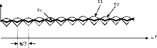 FIGURE 10.11 Voltage waveforms of the three-phase double-star rectifier.  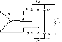 FIGURE 10.12 Three-phase bridge rectifier. Similarly, using Eq. (10.6), the rms value of the output voltage can be found as  .271/3 (ysin) /3 9a/3 = 42 + = (10.49) (10.50) The diodes are numbered in the order of conduction sequences and the conduction angle of each diode is 2я/3. The conduction sequence for diodes is 12, 23, 34, 45, 56, and 61. The voltage and current waveforms of the three-phase bridge rectifier are shown in Fig. 10.13. The line voltage is 1.73 times the phase voltage of a three-phase star-connected source. It is permissible to use any combination of star- or delta-connected primary and secondary windings because the currents associated with the secondary windings are symmetrical. Using Eq. (10.1), the average value of the output can be found as 27Г/3 л/з VsinOde (10.47) = 1.654 (10.48) 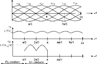 D6 conducts D2 conducts 571/3 2n D4 conducts , conducts conducts FIGURE 10.13 rectifier. Voltage and current waveforms of the three-phase bridge In addition, the rms current in each transformer secondary winding can also be found as  = 0.78 L (10.51) and the rms current through a diode is = 0.552 (10.52) where = 1.73 VJR. Based on Eqs. (10.48), (10.50), (10.51), and (10.52), all the important design parameters of the three-phase star rectifier can be evaluated as hsted in Table 10.3. The dc output voltage is slightly lower than the peak line voltage or 2.34 times the rms phase voltage. The Peak Repetitive Reverse Voltage (Vrrm) rating of the employed diodes is 1.05 times the dc output voltage, and the Peak Repetitive Forward Current (/ркм) rating of the employed diodes is 0.579 times the dc output current. Therefore, this three-phase bridge rectifier is very efficient and popular wherever both dc voltage and current requirements are high. In many applications, no additional filter is required because the output ripple voltage is only 4.2%. Even if a filter is required, the size of the filter is relatively small because the ripple frequency is increased to six times the input frequency. 10.3.3 operation of Rectifiers with Finite Source Inductance It has been assumed in the preceding sections that the commutation of current from one diode to the next takes place instantaneously when the interphase voltage assumes necessary polarity. In practice, this is hardly possible because there are finite inductances associated with the source. For the purpose of discussing the effects of the finite source inductance, a three- phase star rectifier with transformer leakage inductances is shown in Fig. 10.14, where Z, /2, /3, denote the leakage inductances associated with the transformer secondary windings. 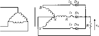 FIGURE 10.14 Three-phase star rectifier with transformer leakage inductances. Refer to Fig. 10.15. At the time that iyn is about to become larger than v, due to leakage inductance Z, the current in cannot faU to zero immediately. Similarly, due to the leakage inductance /2, the current in D2 cannot increase immediately to its full value. The result is that both diodes conduct for a certain period, which is caUed the overlap (or commutation) angle. The overlap reduces the rectified voltage Vi as shown in the upper voltage waveform of Fig. 10.15. If aU the leakage inductances are equal, that is, = /2 = /3 = then the amount of reduction of dc output voltage can be estimated as mfiljy where m is the ratio of the lowest-ripple frequency to the input frequency. For example, for a three-phase star rectifier operating from a 60-Hz supply with an average load current of 50 A, the amount of reduction of the dc output voltage is 2.7 V if the leakage inductance in each secondary winding is 300 iH. 10.4 Poly-Phase Diode Rectifiers 10.4.1 Six-Phase Star Rectifier A basic six-phase star rectifier circuit is shown in Fig. 10.16. The six-phase voltages on the secondary are obtained by 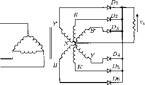 FIGURE 10.16 Six-phase star rectifier. means of a center-tapped arrangement on a star-connected three-phase winding. Therefore, it is sometimes referred to as a three-phase full-wave rectifier. The diode in a particular phase conducts during the period when the voltage on that phase is higher than that on the other phases. The voltage waveforms of each phase and the load are shown in Fig. 10.17. It is clear that, unlike the three-phase star rectifier circuit, the conduction angle of each diode is я/3 instead of 2я/3. Currents flow in only one rectifying element at a time, resulting in a low average current, but a high peak-to-average current ratio in the diodes and poor transformer secondary utilization. Nevertheless, the dc currents in the secondary of the six-phase star rectifier cancel in the secondary windings like a fuU-wave rectifier and, therefore, core saturation is not encountered. This six-phase star circuit is attractive in applications that require a low ripple factor and a common cathode or anode for the rectifiers. By considering the output voltage provided by v between я/3 and 2я/3, the average value of the output voltage can be found as 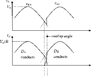 FIGURE 10.15 Waveforms during commutation in Fig. 10.14. 27Г/3 sin 0 de (10.53) 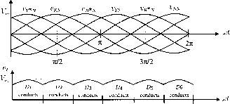 7Г/3 27U/3 n 4K/3 571/3 2n FIGURE 10.17 Voltage waveforms of the six-phase star rectifier. dc = . = 0.955 (10.54) Similarly, the rms value of the output voltage can be found as  271/3 (ysin) (10.55) individual bridge rectifier) to 1%. The combined bridge rectifier is referred to as a six-phase series bridge rectifier. In the six-phase series bridge rectifier shown in Fig. 10.18, let y* be the peak voltage of the delta-connected secondary. The peak voltage between the fines of the star-connected secondary is also У*. The peak vohage across the load, denoted as У^, is equal to 2 У* x cos(/12) or 1.932 У* because there is я/6-phase displacement between the secondaries. The ripple frequency is 12 times the mains frequency. The average value of the output voltage can be found as In addition, the rms current in each transformer secondary winding can be found as (10.57) where = VJR. Based on the relationships stated in Eqs. (10.55), (10.56), and (10.57), all the important design parameters of the six-phase star rectifier can be evaluated, as listed in Table 10.4 (given at the end of Section 10.4.3). dc=- 771/12 y sin e de 571/12 (10.58) dc = vj- = 0.98862 y, (10.59) The rms value of the output voltage can be found as  771/12 (Vsinefde (10.60) 571/12 12 /я 1 (10.61) 10.4.2 Six-Phase Series Bridge Rectifier The star- and delta-connected secondaries have an inherent я/6-phase displacement between their output voltages. When a star-connected bridge rectifier and a delta-connected bridge rectifier are connected in series as shown in Fig. 10.18, the combined output voltage will have a doubled ripple frequency (12 times that of the mains). The ripple of the combined output voltage will also be reduced from 4.2% (for each The rms current in each transformer secondary winding is 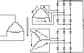 The rms current through a diode is (10.62) 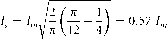 FIGURE 10.18 Six-phase series bridge rectifier. (10.63) where = VJR. Based on Eqs. (10.59), (10.61), (10.62), and (10.63), all the important design parameters of the six-phase series bridge rectifier can be evaluated, as listed in Table 10.4. 10.4.3 Six-Phase Parallel Bridge Rectifier The six-phase series bridge rectifier described in the preceding is useful for high-output voltage applications. Fiowever, for high-output current applications, the six-phase parallel bridge rectifier (with an interphase transformer) shown in Fig. 10.19 should be used. TABLE 10.4 Important design parameters of six-phase rectifier circuits with resistive load
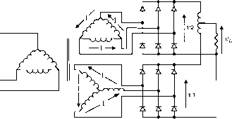 FIGURE 10.19 Six-phase parallel bridge rectifier. The interphase transformer causes the output voltage Vi to be the average of the rectified voltages v and V2 as shown in Fig. 10.20. As with the six-phase series bridge rectifier, the output ripple frequency of the six-phase paraUel bridge rectifier is also 12 times that of the mains. Further filtering on the output voltage is usually not required. Assuming a balanced circuit, the output currents of two three-phase units (flowing in opposite directions in the interphase transformer winding) produce no dc magnetization current. All the important design parameters of the six-phase parallel rectifiers with interphase transformer are also listed in Table 10.4. 10.5 Filtering Systems in Rectifier Circuits Filters are commonly employed in rectifier circuits for smoothing out the dc output voltage of the load. They are classified as inductor-input dc filters and capacitor-input dc filters. Inductor-input dc filters are preferred in high-power applications because more efficient transformer operation is obtained due to the reduction in the form factor of the rectifier current. Capacitor-input dc filters can provide volu-metrically efficient operation, but they demand excessive turn-on and repetitive surge currents. Therefore, capacitor-input dc filters are suitable only for lower-power systems where close regulation is usually achieved by an electronic regulator cascaded with the rectifier.  TZ/6 FIGURE 10.20 Voltage waveforms of the six-phase bridge rectifier with interphase transformer. 10.5.1 Inductive-Input dc Filters The simplest inductive-input dc filter is shown in Fig. 10.21a. The output current of the rectifier can be maintained at a steady value if the inductance of is sufficiently large (coL R). The filtering action is more effective in heavy load conditions than in light load conditions. If the ripple attenuation is not sufficient even with large values of inductance, an L-section filter as shown in Fig. 10.21b can be used for further filtering. In practice, multiple L-section filters can also be employed if the requirement on the output ripple is very stringent. 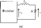
FIGURE 10.21 Inductive-input dc filters, (a) Simplest inductive-input dc filter; (b) L-section filter. For the simple inductive-input dc filter shown in Fig. 10.21a, the ripple is reduced by the factor R + ilnf.Lf (10.64) where is the ripple voltage before filtering, is the ripple voltage after filtering, and is the ripple frequency. For the inductive-input dc filter shown in Fig. 10.21b, the amount of reduction in the ripple voltage can be estimated as 1 - {Inf.flfCf where is the ripple frequency, if > l/lnfCf. 10.5.1.1 Voltage and Current Waveforms for a Full-Wave Rectifier with Inductor-Input dc Filter Figure 10.22 shows a single-phase full-wave rectifier with an inductor-input dc filter. The voltage and current waveforms are illustrated in Fig. 10.23. When the inductance of is infinite, the current through the inductor and the output voltage are constant. When inductor Ljr is finite, the current through the inductor has a ripple component, as shown by the dotted lines in Fig. 10.23. If the input inductance is too small, the current decreases to zero (becoming discontinuous) during a portion of the time between the peaks of the rectifier output voltage. The minimum value of inductance required to maintain a continuous current is known as the critical inductance L(j. ->h inductor with ......-aKinfinite inductance 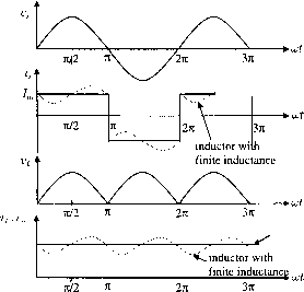 inductor with infinite inductance FIGURE 10.23 Voltage and current waveforms of full-wave rectifier with inductor-input dc filter. 10.5.1.2 Critical Inductance In the case of single-phase full-wave rectifiers, the critical (10.65) inductance can be found as Full-wave Lq = (10.66) where /J is the input mains frequency. In the case of polyphase rectifiers, the critical inductance can be found as Polyphase = 3nm(m - l)fi (10.67) where m is the ratio of the lowest ripple frequency to the input frequency, for example, m = 6 for a three-phase bridge rectifier. 10.5.1.3 Determining the Input Inductance for a Given Ripple Factor In practice, the choice of the input inductance depends on the required ripple factor of the output voltage. The ripple voltage of a rectifier without filtering can be found by means of Fourier analysis. For example, the coefficient of the nth harmonic component of the rectified voltage Vi shown in Fig. 10.22 can be expressed as n(n - 1) (10.68) FIGURE 10.22 A full-wave rectifier with inductor-input dc filter. where /7 = 2, 4, 8,..., etc. The dc component of the rectifier voltage is given by Eq. (10.5). Therefore, in addition to Eq. (10.27), the ripple factor can also be expressed as RF = я=2,4,8 \ (10.69) Considering only the lowest-order harmonic (/7 = 2), the output ripple factor of a simple inductor-input dc filter (without Cjr) can be found, from Eqs. (10.64) and (10.69), as Fihered RF = 0.4714 1 + {AnfLf/Rf (10.70) 10.5.1.4 Harmonics of the Input Current In general, the total harmonic distortion (THD) of an input current is defined as --C4- FIGURE 10.24 Equivalent circuit for input ac filter. The power factor of the circuit shown in Fig. 10.22 can be improved by instaUing an ac filter between the source and the rectifier, as shown in Fig. 10.24. Considering only the harmonic components, the equivalent circuit of the rectifier given in Fig. 10.24 can be found as shown in Fig. 10.25. The rms value of the nth harmonic current appearing in the supply can then be obtained using the current-divider rule.  THD = JU -1 (10.71) where L is the rms value of the input current and Li and the rms value of the fundamental component of the input current. The THD can also be expressed as THD = J E я=2,3,4 Vsl (10.72) where L is the rms value of the nth harmonic component of the input current. Moreover, the input power factor is defined as PF = cos(/) (10.73) where ф is the displacement angle between the fundamental components of the input current and voltage. Assume that inductor of the circuit shown in Fig. 10.22 has an infinitely large inductance. The input current is then a square wave. This input current contains undesirable higher harmonics that reduce the input power factor of the system. The input current can be easily expressed as 71 п=1,3,5П (10.74) The rms values of the input current and its fundamental component are L and 4 (яа/2), respectively. Therefore, the THD of the input current of this circuit is 0.484. As the displacement angle ф = 0, the power factor is 4/(яа/2) = 0.9. 1 - (2пп0ЦС, (10.75) where is the rms value of the nth harmonic current of the rectifier. Applying Eq. (10.73) and knowing IrJIn = 1/ from Eq. (10.74), the THD of the rectifier with input fiher shown in Fig. 10.24 can be found as Filtered THD = J E V n=3,5 1 - {InnffUC, (10.76) The important design parameters of typical single-phase and three-phase rectifiers with inductor-input dc filter are listed in Table 10.5. Note that, in a single-phase half-wave rectifier, a freewheehng diode is required to be connected across the input of the dc filters such that the flow of load current can be maintained during the negative half-cycle of the supply voltage. 10.5.2 Capacitive-Input dc Filters Figure 10.26 shows a fuU-wave rectifier with capacitor-input dc filter. The voltage and current waveforms of this rectifier are FIGURE 10.25 Equivalent circuit for input ac filter. 1 ... 12 13 14 15 16 17 18 ... 91 |
|||||||||||||||||||||||||||||||||||||||||||||||||||||||||||||||||||||||||||||||||||||||||||||||||||||||||||||||||||||||||||||||||||||||||||||||||||||||||||||||||||||||||||||||||||||||||||||||||||||||||||||
|
© 2026 AutoElektrix.ru
Частичное копирование материалов разрешено при условии активной ссылки |