 |
 |
 |
| Главная Журналы Популярное Audi - почему их так назвали? Как появилась марка Bmw? Откуда появился Lexus? Достижения и устремления Mercedes-Benz Первые модели Chevrolet Электромобиль Nissan Leaf |
Главная » Журналы » Metal oxide semiconductor 1 ... 16 17 18 19 20 21 22 ... 91 Three-Phase Controlled Rectifiers Juan W. Dixon, Ph.D. Department of Electrical Engineering, Catholic University of Chile, Vicuna Mackenna 4860 Santiago, Chile 6904411 12.1 Introduction........................................................................................ 183 12.2 Line-Commutated Controlled Rectifiers................................................... 183 12.2.1 Three-Phase Half-Wave Rectifier 12.2.2 Six-Pulse or Double Star Rectifier 12.2.3 Double Star Rectifier with Interphase Connection 12.2.4 Three-Phase Full-Wave Rectifier or Graetz Bridge 12.2.5 Half-Controlled Bridge Converter 12.2.6 Commutation 12.2.7 Power Factor 12.2.8 Harmonic Distortion 12.2.9 Special Configurations for Harmonic Reduction 12.2.10 Applications of Line-Commutated Rectifiers in Machine Drives 12.2.11 Applications in HVDC Power Transmission 12.2.12 Dual Converters 12.2.13 Cycloconverters 12.2.14 Harmonic Standards and Recommended Practices 12.3 Force-Commutated Three-Phase Controlled Rectifiers............................... 196 12.3.1 Basic Topologies and Characteristics 12.3.2 Operation of the Voltage Source Rectifier 12.3.3 PWM Phase-to-Phase and Phase-to-Neutral Voltages 12.3.4 Control of the DC Link Voltage 12.3.5 New Technologies and Apphcations of Force-Commutated Rectifiers References........................................................................................... 210 12.1 Introduction Three-phase controlled rectifiers have a wide range of applications, from small rectifiers to large high voltage direct current (FiVDC) transmission systems. They are used for electrochemical processes, many kinds of motor drives, traction equipment, controlled power supplies, and many other applications. From the point of view of the commutation process, they can be classified into two important categories: line-commutated controlled rectifiers (thyristor rectifiers); and force-commutated PWM rectifiers. 12.2 Line-Commutated Controlled Rectifiers 12.2.1 Three-Phase Half-Wave Rectifier Figure 12.1 shows the three-phase half-wave rectifier topology. To control the load voltage, the half-wave rectifier uses three common-cathode thyristor arrangement. In this figure, the power supply and the transformer are assumed ideal. The thyristor will conduct (ON state), when the anode-to-cathode voltage Vj is positive, and a firing current pulse ig is applied to the gate terminal. Delaying the firing pulse by an angle a controls the load voltage. As shown in Fig. 12.2, the firing angle a is measured from the crossing point between the phase supply voltages. At that point, the anode-to-cathode thyristor voltage Vjj begins to be positive. Figure 12.3 shows that the possible range for gating delay is between a = 0° and a = 180°, but because of commutation problems in actual situations, the maximum firing angle is hmited to 160°. As shown in Fig. 12.4, when the load is resistive, current i has the same waveform as the load voltage. As the load becomes more and more inductive, the current flattens and finally becomes constant. The thyristor goes to the nonconducting condition (OFF state) when the following thyristor is switched ON, or the current tries to reach a negative value. With the help of Fig. 12.2, the load average voltage can be evaluated and is given by ТГ max тг/З+а -7г/3+а sin я/3 cos cot d(cot) cos a 1.17- V-cosa (12.1) where V is the secondary phase-to-neutral peak voltage, VfN t mean square (rms) value, and ш is the angular frequency of the main power supply. It can be seen from Eq. (12.1) that the load average voltage Vj is modified by changing firing angle a. When a is <90°, Vp, is positive and when a is >90°, the average dc voltage becomes negative. In such a case, the rectifier begins to work as an inverter, and the load needs to be able to generate power reversal by reversing its dc voltage. Power Supply Power Transformer  LOAD FIGURE 12.1 Three-phase half-wave rectifier. 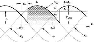 FIGURE 12.2 Instantaneous dc voltage v average dc voltage F and firing angle a. The ac currents of the half-wave rectifier are shown in Fig. 12.5. This drawing assumes that the dc current is constant (very large L). Disregarding commutation overlap, each valve conducts during 120° per period. The secondary currents (and thyristor currents) present a dc component that is undesirable, and makes this rectifier not useful for high power applications. The primary currents show the same waveform, but with the dc component removed. This very distorted waveform requires an input filter to reduce harmonics contamination. The current waveforms shown in Fig. 12.5 are useful for designing the power transformer. Starting from prim (pnm)f-N -prim sec - (sec)/-]V sec (12.2) Pd = Vd Id where VAp. and VA are the ratings of the transformer for the primary and secondary side, respectively. Here Pj is the power transferred to the dc side. The maximum power 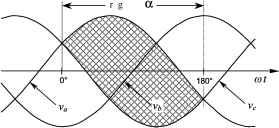 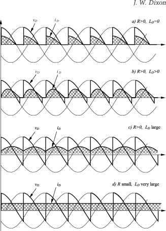 FIGURE 12.4 DC current waveforms. transfer is with a = 0° (or a = 180°). Then, to establish a relation between ac and dc voltages, Eq. (12.1) for a = 0° is required: Уп = 1.17.У, (sec)/-]V (12.3)
FIGURE 12.3 Possible range for gating delay in angle a. FIGURE 12.5 AC current waveforms for the half-wave rectifier. 12 Three-Phase Controlled Rectifiers and Vp, = lA7-a-V! (prim)/-iV (12.4) where a is the secondary to primary turn relation of the transformer. On the other hand, a relation between the currents is also possible to obtain. With the help of Fig. 12.5, voltage is higher than that from the half-wave rectifier, and its average value is given by T / max 7г/6+а -7г/6+а sin я/6 я/6 COS cot d(CDt) COS a 1.35. V.cosa (12.8) rrms rrms prim - (12.5) (12.6) Combining Eqs. (12.2) to (12.6), it yields yAprin. = 1.21.P, У4ес = 1.48.Р^, (12.7) Equation (12.7) shows that the power transformer has to be oversized 21% at the primary side, and 48% at the secondary side. Then a special transformer has to be built for this rectifier. In terms of average VA, the transformer needs to be 35% larger that the rating of the dc load. The larger rating of the secondary respect to primary is because the secondary carries a dc component inside the windings. Furthermore, the transformer is oversized because the circulation of current harmonics does not generate active power. Core saturation, due to the dc components inside the secondary windings, also needs to be taken into account for iron oversizing. 12.2.2 Six-Pulse or Double Star Rectifier The thyristor side windings of the transformer shown in Fig. 12.6 form a six-phase system, resulting in a 6-pulse starpoint (midpoint connection). Disregarding commutation overlap, each valve conducts only during 60° per period. The direct Mr Г #1Р Mr Mr Л FIGURE 12.6 Six-pulse rectifier. The dc voltage ripple is also smaller than the one generated by the half-wave rectifier, due to the absence of the third harmonic with its inherently high amplitude. The smoothing reactor L is also considerably smaller than the one needed for a 3-pulse (half-wave) rectifier. The ac currents of the 6-pulse rectifier are shown in Fig. 12.7. The currents in the secondary windings present a dc component, but the magnetic flux is compensated by the double star. As can be observed, only one valve is fired at a time, and then this connection in no way corresponds to a parallel connection. The currents inside the delta show a symmetrical waveform, with 60° conduction. Finally, due to the particular transformer connection shown in Fig. 12.6, the source currents also show a symmetrical waveform, but with 120° conduction. Evaluation of the rating of the transformer is done in similar fashion to the way the half-wave rectifier is evaluated: yApri = 1.28.P У4ес= 1.81.P, (12.9) Thus, the transformer must be oversized 28% at the primary side, and 81% at the secondary side. In terms of size it has an average apparent power of 1.55 times the power Pp, (55% oversized). Because of the short conducting period of the valves, the transformer is not particularly well utilized. 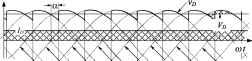 Tzzr I I FIGURE 12.7 AC current waveforms for the 6-pulse rectifier. 12.2.3 Double Star Rectifier with Interphase Connection This topology works as two half-wave rectifiers in paraUel, and is very useful when high dc current is required. An optimal way to reach both good balance and eliminaton of harmonics is through the connection shown in Fig. 12.8. The two rectifiers are shifted by 180°, and their secondary neutrals are connected through a middle-point autotransformer, caUed an interphase transformer . The interphase transformer is connected between the two secondary neutrals, and the middle point at the load return. In this way, both groups operate in paraUel. Half the direct current flows in each half of the interphase transformer and then its iron core does not become saturated. The potential of each neutral can osciUate independently, generating an almost triangular voltage waveform (vj) in the interphase transformer, as shown in Fig. 12.9. As this converter works like two half-wave rectifiers connected in parallel, the load average voltage is the same as in Eq. (12.1): Va. la 1.17 - f-N COS a (12.10) where VJ is the phase-to-neutral rms voltage at the valve side of the transformer (secondary). The Fig. 12.9 also shows the two half-wave rectifier voltages, related to their respective neutrals. Voltage v represents the potential between the common cathode connection and the 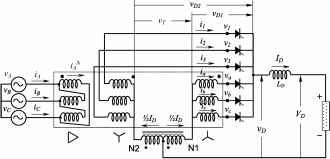 FIGURE 12.8 Double star rectifier with interphase transformer. 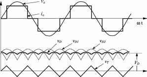
FIGURE 12.10 Firing angle variation from a = 0° to 180°. neutral N1. The voltage y)! is between the common cathode connection and N2. It can be seen that the two instantaneous voltages are shifted, which gives as a resuh a voltage v that is smoother than v and yj- Figure 12.10 shows how v, v, yj change when the firing angle changes from a = 0° to a = 180°. The transformer rating in this case is VApri = 1.05.P V4 = 1.48.P, (12.11) and the average rating power wiU be 1.26P2), which is better than the previous rectifiers (1.35 for the half-wave rectifier, and 1.55 for the 6-pulse rectifier). Thus the transformer is weU utihzed. Figure 12.11 shows ac current waveforms for a rectifier with interphase transformer. 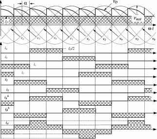 FIGURE 12.9 Operation of the interphase connection for a = 0°. FIGURE 12.11 transformer. AC current waveforms for the rectifier with interphase 12.2.4 Three-Phase Full-Wave Rectifier or Graetz Bridge Parallel connection via interphase transformers permits the implementation of rectifiers for high current applications. Series connection for high voltage is also possible, as shown in the full-wave rectifier of Fig. 12.12. With this arrangement, it can be seen that the three common cathode valves generate a positive voltage with respect to the neutral, and the three common anode valves produce a negative voltage. The result is a dc voltage twice the value of the half-wave rectifier. Each half of the bridge is a 3-pulse converter group. This bridge connection is a two-way connection, and alternating currents flow in the valve-side transformer windings during both half periods, avoiding dc components into the windings, and saturation in the transformer magnetic core. These characteristics make the so-called Graetz bridge the most widely used line-commutated thyristor rectifier. The configuration does not need any special transformer, and works as a 6-pulse rectifier. The series characteristic of this rectifier produces a dc voltage twice the value of the half-wave rectifier. The load average voltage is given by Vn - 2/371 COS cot d(cot) = 2. -7г/3+а sin я/3 cos a 2.34 . cos a (12.12) 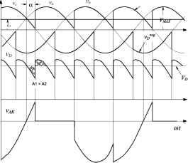 FIGURE 12.13 Voltage waveforms for the Graetz bridge. 12.14 shows the currents of the rectifier, which assumes that is large enough to keep the dc current smooth. The example is for the same AY transformer connection shown in the topology of Fig. 12.12. It can be noted that the secondary currents do not carry any dc component, thereby avoiding overdesign of the windings and transformer saturation. These two figures have been drawn for a firing angle a of 30°. The perfect symmetry of the currents in all windings and lines is one of the reasons why this rectifier is the most popular of its type. The transformer rating in this case is 3. V2-yf cos a 1.35 V!. cos a (12.13) where V is the peak phase-to-neutral voltage at the secondary transformer terminals, V its rms value, and V!!y the rms phase-to-phase secondary voltage, at the valve terminals of the rectifier. Figure 12.13 shows the voltages of each half-wave bridge of this topology v° and v, the total instantaneous dc voltage Vp, and the anode-to-cathode voltage v in one of the bridge thyristors. The maximum value of v is /3 Vax which is the same as that of the half-wave converter and the interphase transformer rectifier. The double star rectifier presents a maximum anode-to-cathode voltage of 2 times Vmax- Figure 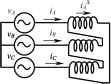 -Л -Л -Л VA =L05-Pr, У4 = 1.05.Р^, (12.14) 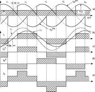 FIGURE 12.12 Three-phase full-wave rectifier or Graetz bridge. FIGURE 12.14 Current waveforms for the Graetz bridge. Ld + a) b) FIGURE 12.15 One-quadrant bridge converter circuits: (a) half-controlled bridge; and (b) free-wheeling diode bridge. As can be noted, the transformer needs to be oversized only 5%, and both primary and secondary windings have the same rating. Again, this value can be compared with the previous rectifier transformers: \35Pjj for the half-wave rectifier; \.55Pjj for the 6-pulse rectifier; and \.26Pjj for the interphase transformer rectifier. The Graetz bridge makes exceUent use of the power transformer. 12.2.5 Half-Controlled Bridge Converter The fully controlled three-phase bridge converter shown in Fig. 12.12 has six thyristors. As already explained here, this circuit operates as a rectifier when each thyristor has a firing angle a of <90° and functions as an inverter for a >90°. If inverter operation is not required, the circuit may be simph-fied by replacing three controlled rectifiers with power diodes, as in Fig. 12.15a). This simplification is economically attractive because diodes are considerably less expensive than thyristors, and they do not require firing angle control electronics. The half-controUed bridge, or semiconverter, is analyzed by considering it as a phase-controUed half-wave circuit in series with an uncontroUed half-wave rectifier. The average dc voltage is given by the foUowing equation: (1 + cosa) (12.15) Then, the average voltage Vj never reaches negative values. The output voltage waveforms of the half-controUed bridge are simUar to those of a fully controlled bridge with a freewheeling diode. The advantage of the free-wheeling diode connection, shown in Fig. 12.15b is that there is always a path for the dc current, independent of the status of the ac line and of the converter. This can be important if the load is inductive-resistive with a large time constant, and there is an interruption in one or more of the line phases. In such a case, the load current could commutate to the free-wheeling diode. 12.2.6 Commutation The description of the converters in the previous sections was based upon the assumption that the commutation was instantaneous. In practice, this is not possible because the transfer of current between two consecutive valves in a commutation group takes a finite time. This time, caUed overlap time, depends on the phase-to-phase voltage between the valves participating in the commutation process, and the line inductance L5 between the converter and power supply. During the overlap time, two valves conduct, and the phase-to-phase voltage drops entirely on the inductances L5. Assuming the dc current I] to be smooth, and with the help of Fig. 12.16, the foUowing relation is deduced: smcot = V4 - Vi (12.16) where i is the current in the valve being fired during the commutation process (thyristor T2 in Fig. 12.16). This current can be evaluated, and it yields: г.г = - - V2 2U cos cot f-f~ (12.17) -►b ON W: OFF Tl i FIGURE 12.16 Commutation process. Constant C is evaluated through initial conditions at the instant when T2 is ignited. In terms of angle, when cot = (x: L = 0 T/sec a/2 coL. cos a Replacing Eq. (12.18) in Eq. (12.17): Vf f i = --(cos a - cos cot) V2 coLg (12.18) (12.19) Before commutation, the current Ij was carried by thyristor Tl (see Fig. 12.16). During the commutation time, the load current Ip) remains constant, i returns through Tl, and Tl is automatically switched-off when the current i reaches the value of Ip,. This happens because thyristors cannot conduct in reverse direction. At this moment, the overlap time lasts, and the current Ip, is then conducted by T2. In terms of angle, when cot = (X -\- /Л, i = Ip where /л is defined as the overlap angler Replacing this final condition in Eq. (12.19) yields: a/2 coLc [cos a - cos(a + fi)] (12.20) To avoid confusion in a real analysis, it has to be remembered that Vf f corresponds to the secondary voltage in the case of transformer utilization. For this reason, the abbreviation sec has been added to the phase-to-phase voltage in Eq. (12.20). During commutation, two valves conduct at a time, which means that there is an instantaneous short circuit between the two voltages participating in the process. As the inductances of each phase are the same, the current i produces the same voltage drop in each L, but with opposite sign because this current flows in reverse direction in each inductance. The phase with the higher instantaneous voltage suffers a voltage drop - Av, and the phase with the lower voltage suffers a voltage increase +Av. This situation affects the dc voltage Vq, reducing its value an amount AV. Figure 12.17 shows the meanings of Av, AV, /л, and i. 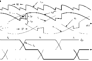 figure 12.17 Effect of the overlap angle on the voltages and currents. The area AV showed in Fig. 12.17 represents the loss of voltage that affects the average voltage Vq, and can be evaluated through the integration of Av during the overlap angle 1Л. The voltage drop Av can be expressed as (12.21) Integrating Eq. (12.21) into the corresponding period (60°) and interval (), at the instant when the commutation begins (a): Tl 2 71-72 Subtracting AVed in Eq. (12.13): [cos a - cos(a + ju)] (12.22) (12.23) 3 V2 Yff cosa-AV ,d (12.24) 3 V2 [cos a + cos(a + ju)] (12.25) [cosfa + ) cosl (12.26) 71 L \ 2/ 2- Equations (12.20) and (12.25) can be written as a function of the primary winding of the transformer, if any transformer. a J - J J a/2 coLc [cos a - cos(a + )] (12.27) 3. V2.a.y/!7 2n [cos a + cos(a + )] (12.28) where a= Vf/Vf}f. With Eqs. (12.27) and (12.28) one obtains: J J IT (12.29) Equation (12.29) allows a very simple equivalent circuit of the converter to be made, as shown in Fig. 12.18. It is important to note that the equivalent resistance of this circuit is not real because it does not dissipate power. From the equivalent circuit, regulation curves for the rectifier under different firing angles are shown in Fig. 12.19. It should be noted that these curves correspond only to an (virtual resistance) - (32/n)aVf.fCOsa Vd FIGURE 12.18 Equivalent circuit for the converter. (3V2/7i)a f.f yi/cosai (3V2/7i)aFcosa2
Ido Id FIGURE 12.19 Direct current voltage regulation curves for rectifier operation. where VJ is the rms value of the voltage v, and the rms value of (fundamental component of i,). Analog relations can be obtained for and v. The apparent power per phase is given by n T T-rms 7-rn The power factor is defined by (12.32) (12.33) By substituting Eqs. (12.30), (12.31) and (12.32) into Eq. (12.33), the power factor can be expressed as follows rrms cos a (12.34) This equation shows clearly that due to the nonsinusoidal waveform of the currents, the power factor of the rectifier is negatively affected by both the firing angle a and the distortion of the input current. In effect, an increase in the distortion of the current produces an increase in the value of FJ in Eq. (12.34), which deteriorates the power factor. 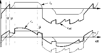 FIGURE 12.20 Effect of the overlap angle on and on thyristor voltage v. ideal situation, but they help in understanding the effect of voltage drop Av on dc voltage. The commutation process and the overlap angle also affects the voltage and anode-to-cathode thyristor voltage, as shown in Fig. 12.20. 12.2.7 Power Factor The displacement factor of the fundamental current, obtained from Fig. 12.14 is cos(/)i = cos a (12.30) In the case of nonsinusoidal current, the active power delivered per phase by the sinusoidal supply is Plf{ Va(t)ia(t)dt = vriT COS ф, (12.31) I . П 12.2.8 Harmonic Distortion The currents of the line-commutated rectifiers are far from being sinusoidal. For example, the currents generated from the Graetz rectifier (see Fig. 12.14b) have the following harmonic content: гл = 2V3. /п COS cot--COS Scot +-COS 7a;t - YYos llcot + (12.35) Some of the characteristics of the currents obtained from Eq. (12.35) include: i) the absence of triple harmonics; ii) the presence of harmonics of order 6; ±1 for integer values of k; iii) those harmonics of orders 6/с + 1 are of positive sequence, and those of orders 6k - I are of negative sequence; and iv) the rms magnitude of the fundamental frequency is v) the rms magnitude of the nth harmonic is: (12.36) (12.37) If either the primary or the secondary three-phase windings of the rectifier transformer are connected in delta, the ac side current waveforms consist of the instantaneous differences between two rectangular secondary currents 120° apart as shown in Fig. 12.14e). The resulting Fourier series for the current in phase a on the primary side is 2V3. 1л =--!]:,( cos cot cos Scot - - cos 7cot - YYos Hot + (12.38) This series differs from that of a star-connected transformer only by the sequence of rotation of harmonic orders 6/cib 1 for odd values of h that is, 5th, 7th, 17th, 19th, etc. 12.2.9 Special Configurations for Harmonic Reduction A common solution for harmonic reduction is through the connection of passive filters, which are tuned to trap a particular harmonic frequency. A typical configuration is shown in Fig. 12.21. Fiowever, harmonics also can be ehminated using special configurations of converters. For example, 12-pulse configuration consists of two sets of converters connected as shown in Fig. 12.22. The resultant ac current is given by the sum of the 11111  Jib jth -О FIGURE 12.21 Typical passive filter for one phase.  two Fourier series of the star connection (Eq. 12.35) and delta connection transformers (Eq. 12.38): COS cot -- COS 1 Icot + - COS 13a;t 11 13 --cos23t + ... (12.39) The series contains only harmonics of order 12/cib 1. The harmonic currents of orders 6k I (with к odd), that is, 5th, 7th, 17th, 19th, etc., circulate between the two converter transformers but do not penetrate the ac network. The resulting line current for the 12-pulse rectifier shown in Fig. 12.23 is closer to a sinusoidal waveform than previous line currents. The instantaneous dc voltage is also smoother with this connection. Fiigher pulse configuration using the same principle is also possible. The 12-pulse rectifier was obtained with a 30° phase-shift between the two secondary transformers. The addition of further appropriately shifted transformers in parallel provides the basis for increasing pulse configurations. For instance, 24-pulse operation is achieved by means of four transformers with 15° phase-shift, and 48-pulse operation requires eight transformers with 7.5° phase-shift. Although theoretically possible, pulse numbers >48 are rarely justified due to the practical levels of distortion found in the supply voltage waveforms. Further, the converter topology becomes more and more complicated. An ingenious and very simple way to reach high pulse operation is shown in Fig. 12.24. This configuration is called dc ripple reinjection. It consists of two parallel converters connected to the load through a multistep reactor. The reactor uses a chain of thyristor-controUed taps, which are connected to symmetrical points of the reactor. By firing the thyristors located at the reactor at the right time, high-pulse operation is reached. The level of pulse operation depends on the number of thyristors connected to the reactor. They multiply the basic level of operation of the two converters. The example of Fig. 12.24 shows a 48-pulse configuration, obtained by the multiplication of basic 12-pulse operation by four reactor thyristors. This technique also can be applied to series connected bridges. Another solution for harmonic reduction is the utilization of active power filters. Active power filters are special pulse width modulated (PWM) converters, able to generate the 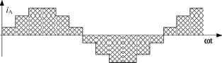 FIGURE 12.22 A 12-pulse rectifier configuration. FIGURE 12.23 Line current for the 12-pulse rectifier. 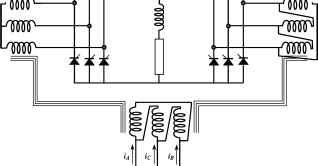 FIGURE 12.24 Direct current ripple reinjection technique for 48-pulse operation. -vvv Shunt Active Filter Line-commutated converter Reference Current Calculation  FIGURE 12.25 Current-controlled shunt active power filter. harmonics the converter requires. Figure 12.25 shows a current-controUed shunt active power filter. 12.2.10 Applications of Line-Commutated Rectifiers in Machine Drives Important applications for line-commutated three-phase controlled rectifiers are found in machine drives. Figure 12.26 shows a dc machine control implemented with a 6-pulse rectifier. Torque and speed are controUed through armature current Ij and excitation current 4. Current Ij is adjusted with V, which is controUed by the firing angle a through Eq. (12.12). This dc drive can operate in two quad- Id = Ia 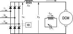 rants - positive and negative dc voltage. This two-quadrant operation aUows regenerative braking when a > 90°, and The converter of Fig. 12.26 also can be used to control synchronous machines, as shown in Fig. 12.27. In this case, a second converter working in the inverting mode operates the machine as a self-controlled synchronous motor. With this second converter, the synchronous motor behaves like a dc motor but has none of the disadvantages of mechanical commutation. This converter is not hne commutated, but machine commutated. The nominal synchronous speed of the motor on a 50 or 60 Hz ac supply is now meaningless, and the upper speed limit is determined by the mechanical limitations of the rotor construction. There is the disadvantage that the rotational emfs required for load commutation of the machine side converter are not avaUable at standstiU and low speeds. In such a case, auxihary force commutated circuits must be used. The line-commutated rectifier through a controls the torque of the machine. This approach gives direct torque control of the commutatorless motor and is analogous to the use of armature current control as shown in Fig. 12.26 for the converter-fed dc motor drive. Line-commutated rectifiers are also used for speed control of wound-rotor induction motors. Subsynchronous and supersynchronous static converter cascades using a naturally commutated dc hnk converter can be implemented. Figure 12.28 shows a supersynchronous cascade for a wound rotor induction motor, using a naturally commutated dc hnk converter. In the supersynchronous cascade shown in Fig. 12.28, the right-hand bridge operates at slip frequency as a rectifier or inverter, while the other operates at network frequency as an inverter or rectifier. Control is difficult near synchronism when shp frequency emfs are insufficient for natural commutation, and special circuit configuration employing forced commutation or devices with a self-turn-off capabUity is necessary for a passage through synchronism. This kind of supersynchronous cascade works better with cycloconverters.  FIRING SIGNALS FIRING SIGNALS POSITION-TO-VELOCITY CONVERTER 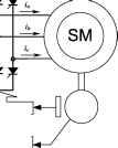 Position sensor FIGURE 12.26 Direct Current machine drive with a 6-pulse rectifier. FIGURE 12.27 Self-controlled synchronous motor drive. 1 ... 16 17 18 19 20 21 22 ... 91 |
||||||||||||||||||||||||||||||||||||||||||||||||||||||||||||||||||||||||||||
|
© 2026 AutoElektrix.ru
Частичное копирование материалов разрешено при условии активной ссылки |