 |
 |
 |
| Главная Журналы Популярное Audi - почему их так назвали? Как появилась марка Bmw? Откуда появился Lexus? Достижения и устремления Mercedes-Benz Первые модели Chevrolet Электромобиль Nissan Leaf |
Главная » Журналы » Metal oxide semiconductor 1 ... 18 19 20 21 22 23 24 ... 91 In this method, there are two important parameters to define: the amphtude modulation ratio, or modulation index m, and the fi-equency modulation ratio p. Definitions are given by Т/ max mod TRIANG (12.68) (12.69) Where Vqd ang amplitudes of Vqd TRiANG respectively. On the other hand, /5 is the frequency of the mains supply and fj the frequency of the triangular carrier. In Fig. 12.51, m = 0.8 and p = 21. When m > I overmodula-tion is defined. The modulation method described in Fig. 12.51 has a harmonic content that changes with p and m. When p < 21, it is recommended that synchronous PWM be used, which means that the triangular carrier and the template should be synchronized. Furthermore, to avoid subharmonics, it is also desired that p be an integer. If p is an odd number, even harmonics will be eliminated. If p is a multiple of 3, then the PWM modulation of the three phases wiU be identical. When m increases, the amplitude of the fundamental voltage increases proportionally, but some harmonics decrease. Under overmodulation, the fundamental voltage does not increase linearly, and more harmonics appear. Figure 12.52 shows the harmonic spectrum of the three-phase PWM voltage waveforms for different values of m, and p = 3k where к is an odd number. Due to the presence of the input inductance L5, the harmonic currents that result are proportionally attenuated with the harmonic number. This characteristic is shown in the current waveforms of Fig. 12.53, where larger p numbers generate cleaner currents. The rectifier that originated the currents of Fig. 12.53 has the foUowing characteristics: Vp, = 450 Vjc, V = 220 Vc, Ls = 3 mH, and input current /5 = 80 Arms. It can be observed that with p > 21 the current distortion is quite smaU. The value of p = 81 in Fig. 12.53 produces an almost pure sinusoidal waveform, and it means 4860 Fiz of switching frequency at 60 Fiz or only 4.050 Fiz in a rectifier operating in a 50-Fiz supply. This switching frequency 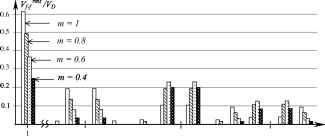 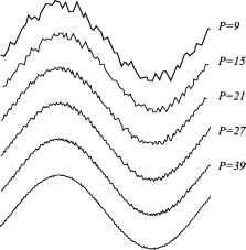 P=81 FIGURE 12.53 Current waveforms for different values of p. can be managed by MOSFETs, IGBTs, and even power Darlingtons. Then p = 81 is feasible for todays low and medium power rectifiers. 12.3.4.3 Voltage-Source Load-Controlled PWM Rectifier A simple method of control for smaU PWM rectifiers (up to 10-20 kW) is based on direct control of the dc current. Figure 12.54 shows the schematic of this control system. The fundamental voltage Vmod modulated by the rectifier is produced by a fixed and unique PWM pattern, which can be carefully selected to eliminate most undesirable harmonics. As the PWM does not change, it can be stored in a permanent digital memory (ROM). The control is based on changing the power angle д between the mains voltage V and fundamental PWM voltage mod-When д changes, the amount of power flow transferred from the ac to the dc side also changes. When the power angle is negative (Vqd lB V), the power flow goes from the ac to the dc side. When the power angle is positive, the power flows p-4 p-2 p p+2 p+4 2p-5 2p-l 2p 2p+l 2p+5 3p-4 3p-2 3p 3p+2 3p+4 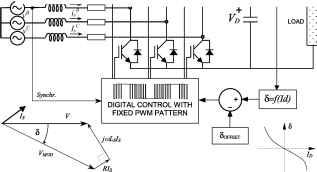 FIGURE 12.52 Harmonic spectrum for SPWM modulation. FIGURE 12.54 Voltage-source load-controlled PWM rectifier. in the opposite direction. Then, the power angle can be controlled through the current 1,. The voltage does not need to be sensed, because this control establishes a stable dc voltage operation for each dc current and power angle. With these characteristics, it is possible to find a relation between Ij and S so as to obtain constant dc voltage for aU load conditions. This relation is given by iD=m = V(cos3 -coLs/R sin 3 - 1) R[l(coLs/Rf] (12.70) From Eq. (12.70) a plot and a reciprocal function S = f{I) are obtained to control the rectifier. The relation between Ij) and д aUows for leading power factor operation and null regulation. The leading power factor operation is shown in the phasor diagram of Fig. 12.54. The control scheme of the voltage source load-controlled rectifier is characterized by the foUowing: i) there are neither input current sensors nor dc voltage sensor; ii) it works with a fixed and predefined PWM pattern; iii) it presents very good StabUity; iv) its stabUity does not depend on the size of the dc capacitor; v) it can work at leading power factor for aU load conditions; and vi) it can be adjusted with Eq. (12.70) to work at zero regulation. The drawback appears when R in Eq. 12.70 becomes negligible, because in such a case the control system is unable to find an equUibrium point for the dc link voltage. This is why this control method is not applicable to large systems. 12.3.5 New Technologies and Applications of Force-Commutated Rectifiers The additional advantages of force-commutated rectifiers with respect to line-commutated rectifiers make them better candidates for industrial requirements. They permit new applications such as rectifiers with harmonic elimination capabUity (active filters), power factor compensators, machine drives with four-quadrant operation, frequency links to connect 50-Hz with 60-Hz systems, and regenerative converters for traction power supplies. Modulation with very fast valves such as IGBTs permit almost sinusoidal currents to be obtained. The dynamics of these rectifiers is so fast that they can reverse power almost instantaneously. In machine drives, current source PWM rectifiers, like the one shown in Fig. 12.35a, can be used to drive dc machines from the three-phase supply. Four-quadrant applications, using voltage-source PWM rectifiers, are extended for induction machines, synchronous machines with starting control, and special machines such as brushless-dc motors. Back-to-back systems are being used in Japan to hnk power systems of different frequencies. 12.3.5.1 Active Power Filter Force-commutated PWM rectifiers can work as active power filters. The voltage-source current-controUed rectifier has the capability to eliminate harmonics produced by other polluting loads. It only needs to be connected as shown in Fig. 12.55. The current sensors are located at the input terminals of the power source, and these currents (instead of the rectifier currents) are forced to be sinusoidal. As there are polluting loads in the system, the rectifier is forced to deliver the harmonics that loads need, because the current sensors do not aUow the harmonics going to the mains. As a result, the rectifier currents become distorted, but an adequate dc capacitor Cj) can keep the dc link voltage in good shape. In this way the rectifier can do its duty, and also eliminate harmonics to the source. In addition, it also can compensate power factor and unbalanced load problems. 12.3.5.2 Frequency Link Systems Frequency link systems permit power to be transferred from one frequency to another one. They are also useful for linking unsynchronized networks. Line-commutated converters are widely used for this application, but they have some drawbacks that force-commutated converters can eliminate. For example, the harmonic filters requirement, the poor power factor, and the necessity to count with a synchronous compensator when generating machines at the load side are absent. Figure 12.56 shows a typical line-commutated system in which a 60-Hz load is fed by a 50-Hz supply. As the 60-Hz side needs excitation to commutate the valves, a synchronous compensator has been required. POLLUTING LOADS I line(a) I line(b) I line(c) LOAD PWM generation Ab Ac Synchr. sin((Ot+(p)  i > sin((ot+ip-nO°) ►( x .........-......Ч - > sin((ot+ip-2AQ°) x ..........................................................у FIGURE 12.55 Voltage-source rectifier with harmonic elimination capability. 50 Hz Passive Filter synchr. 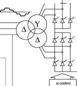 Id Ld 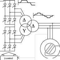 60 Hz Master Control Excitation Voltage Synchronous Compensator Pasive Filter FIGURE 12.56 Frequency link systems with line-commutated converters. In contrast, an equivalent system with force-commutated converters is simpler, cleaner, and more reliable. It is implemented with a dc voltage-controUed rectifier, and another identical converter working in the inversion mode. The power factor can be adjusted independently at the two ac terminals, and filters or synchronous compensators are not required. Figure 12.57 shows a frequency link system with force-commutated converters. each bridge are shifted to cancel harmonics. The example uses sinusoidal PWM that are with triangular carrier shifted. The waveforms of the input currents for the series connection system are shown in Fig. 12.59. The frequency modulation ratio shown in this figure is for p = 9. The carriers are shifted by 90° each to obtain harmonics canceUation. Shifting of the carriers Sj depends on the number of converters in series (or in paraUel), and is given by 12.3.5.3 Special Topologies for High-Power Applications Fiigh-power applications require series- and/or parallel-connected rectifiers. Series and paraUel operation with force-commutated rectifiers aUow improving the power quality because harmonic cancellation can be applied to these topologies. Figure 12.58 shows a series connection of force-commu-tated rectifiers, where the modulating carriers of the valves in 50 Hz PWM CONVERTER PWM I DC LINK VOLTAGE CONTROL 60 Hz CONVERTER POWER CONTROL FIGURE 12.57 Frequency link systems with force-commutated converters. (12.71) where n is the number of converters in series or in paraUel. It can be observed that despite the low value of p, the total current becomes quite clean, and clearly better than the current of one of the converters in the chain. The harmonic cancellation with series- or paraUel-connected rectifiers, using the same modulation but the carriers shifted, is quite effective. The resultant current is better with n converters and frequency modulation p = pi than with one converter and p = n- p. This attribute is verified in Fig. 12.60, where the total current of four converters in series with p = 9 and carriers shifted is compared with the current of only one converter and p = 36. This technique also aUows for the use of valves with slow commutation times, such as high-power GTOs. Generally, high-power valves have low commutation times and hence the paraUel and/or series options remain very attractive. Another special topology for high power was implemented for ABB (Asea Brown Boveri) in Bremen. A 100-MW power converter supphes energy to the railways at l Fiz. It uses basic Fi bridges like the one shown in Fig. 12.61, connected to the load through power transformers. These transformers are MAINS SUPPLY 9 f -Wpir- -W ШР- -whnnnp- SPWM generation - VVW SPWM generation g- VVW SPWM generation - VVW Vmo/Vmo/ Vt(3) SPWM generation VMOD lv l,., С MONITOR  FIGURE 12.58 Series connection system with force-commutated rectifiers. Current in one of the four converters in series 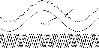 FIGURE 12.59 Input currents and carriers of the series connection system of Fig. 12.58. Figure 12.64 shows the voltage waveforms for different number of converters connected in the bridge. It is clear that the larger the number of converters, the better the voltage. Another interesting result with this converter is that the ac voltages become modulated by both pulsewidth and amphtude (PWM and AM). This is because when the pulse modulation changes, the steps of the amplitude change. The maximum number of steps of the resultant voltage is equal to the number of converters. When the voltage decreases, some steps disappear, and then the amplitude modulation becomes a discrete function. Figure 12.65 shows the amplitude modulation of the voltage. Total current with four converters in series and p9  FIGURE 12.60 Four converters in series and p = 9y compared with one converter and p = 36. connected in paraUel at the converter side, and in series at the load side. The system uses SPWM with triangular carriers shifted, and depending on the number of converters connected in the chain of bridges, the voltage waveform becomes more and more sinusoidal. Figure 12.62 shows a back-to-back system using a chain of 12 Fi converters connected as shown in Fig. 12.61b. The ac voltage waveform obtained with the topology of Fig. 12.62 is displayed in Fig. 12.63. It can be observed that the voltage is formed by smaU steps that depend on the number of converters in the chain (12 in this case). The current is almost perfectly sinusoidal. 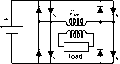 load FIGURE 12.61 The H modulator: (a) one bridge; and (b) bridge connected in series at load side through isolation transformers. 12.3.5.4 Machine Drives Applicarions One of the most important applications of force-commutated rectifiers is in machine drives. Line-commutated thyristor converters have hmited applications because they need excitation to extinguish the valves. This limitation do not aUow the use of line-commutated converters in induction machine drives. On the other hand, with force-commutated converters four-quadrant operation is achievable. Figure 12.66 shows a typical frequency converter with a force-commutated rectifier-inverter link. The rectifier side controls the dc link, and the inverter side controls the machine. The machine can be a synchronous, brushless dc, or induction machine. The reversal of both speed and power are possible with this topology. At the rectifier side, the power factor can be controUed, and even with an inductive load such as an induction machine, the source can see the load as capacitive or resistive. Changing the frequency of the inverter controls the machine speed, and the torque is controUed through the stator currents and torque angle. The inverter wiU become a rectifier during regenerative braking, which is possible by making slip negative in an induction machine, or by making the torque angle negative in synchronous and brushless dc machines. A variation of the drive of Fig. 12.66 is found in electric traction applications. Battery-powered vehicles use the inverter as a rectifier during regenerative braking, and sometimes the inverter is also used as a battery charger. In this case, the rectifier can be fed by a single-phase or by a three-phase system. Figure 12.67 shows a battery-powered electric bus system. This system uses the power inverter of the traction motor as a rectifier for two purposes: regenerative braking; and as a battery charger fed by a three-phase power source. 12.3.5.5 Variable Speed Power Generarion Power generation at 50 or 60 Fiz requires constant speed machines. In addition, induction machines are not currently used in power plants because of magnetization problems. With the use of frequency-link force-commutated converters, variable-speed constant-frequency generation becomes possible. 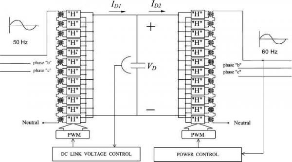 POWER CONVERTERS Phase a FIGURE 12.62 Frequency link with force-commutated converters and sinusoidal voltage modulation. even with induction generators. The power plant in Fig. 12.68 shows a wind generator implemented with an induction machine, and a rectifier-inverter fi-equency link connected to the utility. The dc link voltage is kept constant with the converter located at the mains side. The converter connected at the machine side controls the slip of the generator and adjusts it according to the speed of wind or power requirements. The utility is not affected by the power factor of the generator, because the two converters keep the coscp of the machine independent of the mains supply. The last one can even be adjusted to operate at leading power factor. 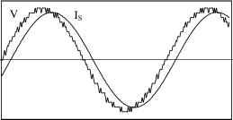 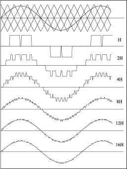 FIGURE 12.63 Voltage and current waveforms with 12 converters. FIGURE 12.64 Voltage waveforms with different numbers of H bridges in series.  0,5 Vnom - OJVnom -p. 0,9 Vnom -►   Variable-speed constant-frequency generation also can be used in either hydraulic or thermal plants. This aUows for optimal adjustment of the efficiency-speed characteristics of the machines. In Japan, wound rotor induction generators working as variable speed synchronous machines are being used as constant frequency generators. They operate in hydraulic plants that are able to store water during low demand periods. A power converter is connected at the shp rings of the generator. The rotor is then fed with variable FIGURE 12.65 Amplitude modulation of the H bridges of Fig. 12.62.  -©-ШГ Ч CONTROL О + Vr CONTROL FIGURE 12.66 Frequency converter with force-commutated converters. traction motor POWER SOURCE   RVNG- ARGNG L TRON SWT SL TOR ol ol ol SOFT-START FILTRES AND SENSORS CONTROL POWER CONVERTER (INVERTER-RECTIFIER) FIGURE 12.67 Electric bus system with regenerative braking and battery charger. BATTERY PACK 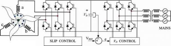 WIND GENERATOR FIGURE 12.68 Variable-speed constant-frequency wind generator. frequency excitation. This aUows the generator to generate at different speeds around the synchronous rotating flux. References 1. G. Moltgen, Line Commutated Thyristor Converters, Siemens Aktiengesellschaft, ВегИп-Munich, Pitman Publishing, London, 1972. 2. G. Moltgen, Converter Engineering, and Introduction to Operation and Theory, John Wiley and Sons, New York, 1984. 3. K. Thorborg, Power Electronics, Prentice-Hall International Ltd., UK, 1988. 4. M. H. Rashid, Power Electronics, Circuits Devices and Applications, Prentice-Hall International Editions, Englewood Cliffs, NJ, 1993. 5. N. Mohan, T. M. Undeland, and W. P. Robbins, Power Electronics: Converters, Applications, and Design, John Wiley and Sons, New York, 1989. 6. J. Arrillaga, D. A. Bradley, and P. S. Bodger, Power System Harmonics, John Wiley and Sons, New York, 1989. 7. J. M. D. Murphy and R G. TurnbuU, Power Electronic Control of AC Motors, Pergamon Press, New York, 1988. 8. M. E. Villablanca and J. Arrillaga, Pulse Multiplication in Parallel Converters by Multilap Control of Interphase Reactor, lEE Proceed-ings-B, 139:1, 13-20 (1992). 9. D. A. Woodford, HVDC Transmission, Professional Report from Manitoba HVDC Research Center, Winnipeg, Manitoba, March 1998. 10. D. R. Veas, J. W. Dixon, and B. T. Ooi, A novel load current control method for a leading power factor voltage source РЕМ rectifier, IEEE Trans on Power Electronics 9:2, 153-159 (1994). 11. L. Moran, E. Mora, R. Wallace, and J. Dixon, Performance analysis of a power factor compensator which simultaneously eliminates line current harmonics, IEEE Power Electronics Specialists Conference, PESC92, Toledo, Espana, June 29 to July 3, 1992. 12. R D. Ziogas, L. Moran, G. Joos, and D. Vincenti, A refined PWM scheme for voltage and current source converters, lEEE-IAS Annual Meeting, 1990, pp. 997-983. 13. W McMurray, Modulation of the chopping frequency in dc choppers and PWM inverters having current hysteresis controllers, IEEE Trans. Ind. Appl, IA-20:4 763-768 (1984). 14. J. W. Dixon and B. T. Ooi, Indirect current control of a unity power factor sinusoidal current boost type three-phase rectifier, IEEE Trans, on Industrial Electronics 35:4, 508-515 (1988). 15. L. Moran, J. Dixon, and R. Wallace, A three-phase active power filter operating with fixed switching frequency for reactive power and current harmonic compensation, IEEE Trans. Industrial Electronics 42:4, 402-408 (1995). 16. M. A. Boost and P. Ziogas, State-of-the-art PWM techniques, a critical evaluation, IEEE Trans, on Industry Applications 24:2, 271-280 (1988). 17. J. W. Dixon and B. T. Ooi, Series and parallel operation of hysteresis current-controlled PWM rectifiers, IEEE Trans, on Industry Applications 2ЪЛ, 644-651 (1989). 18. В. Т. Ooi, J. W. Dixon, A. B. Kulkarni, and M. Nishimoto, An integrated AC drive system using a controlled-current PWM rectifier/inverter link, IEEE Trans, on Power Electronics 3:1, 64-71 (1988). DC-DC Converters Dariusz Czarkowski, Ph.D. Department of Electrical and Computer Engineering. Polytechnic University, Six Metrotech Center, Brooklyn, m 11201 USA 13.1 Introduction..................................................................................... 211 13.2 DC Choppers.................................................................................... 212 13.3 Step-Down (Buck) Converter.............................................................. 213 13.3.1 Basic Converter 13.3.2 Transformer Versions of Buck Converter 13.4 Step-Up (Boost) Converter................................................................. 215 13.5 Buck-Boost Converter........................................................................ 216 13.5.1 Basic Converter 13.5.2 Flyback Converter 13.6 Cuk Converter.................................................................................. 218 13.7 Effects of Parasitics............................................................................ 218 13.8 Synchronous and Bidirectional Converters............................................. 220 13.9 Control Principles.............................................................................. 221 13.10 Applications of DC-DC Converters...................................................... 223 References........................................................................................ 224 13.1 Introduction Modern electronic systems require high-quality, smaU, lightweight, reliable, and efficient power supphes. Linear power regulators, whose principle of operation is based on a voltage or current divider, are inefficient. This is because they are limited to output voltages smaUer than the input voltage, and also their power density is low because they require low-frequency (50 or 60 Fiz) line transformers and filters. Linear regulators can, however, provide a very high-quality output voltage. Their main area of application is at low power levels. Electronic devices in linear regulators operate in their active (linear) modes, but at higher power levels switching regulators are used. Switching regulators use power electronic semiconductor switches in on and off states. Because there is a smaU power loss in those states (low voltage across a switch in the on state, zero current through a switch in the off state), switching regulators can achieve high energy conversion efficiencies. Modern power electronic switches can operate at high frequencies. The higher the operating frequency, the smaller and lighter the transformers, filter inductors, and capacitors. In addition, the dynamic characteristics of converters improve with increasing operating frequencies. The bandwidth of a control loop is usually determined by the corner frequency of the output filter. Therefore, high operating frequencies aUow for achieving a faster dynamic response to rapid changes in the load current and/or the input voltage. Fiigh-frequency electronic power processors are used in dc-dc power conversion. The functions of dc-dc converters are: to convert a dc input voltage into a dc output voltage to regulate the dc output voltage against load and line variations; to reduce the ac voltage ripple on the dc output voltage below the required level; to provide isolation between the input source and the load (isolation is not always required); to protect the supplied system and the input source from electromagnetic interference (EMI); and to satisfy various international and national safety standards. The dc-dc converters can be divided into two main types: hard-switching pulsewidth modulated (PWM) converters, and resonant and soft-switching converters. This chapter deals with PWM dc-dc converters, which have been very popular for the last three decades, and that are widely used at aU power levels. Topologies and properties of PWM converters are weU understood and described in the literature. Advantages of PWM converters include low component count, high efficiency, constant frequency operation, relatively simple control and commercial availability of integrated circuit controUers, and ability to achieve high conversion ratios for both step-down and step-up application. A disadvantage of PWM dc-dc converters is that PWM rectangular voltage and current waveforms cause turn-on and turn-off losses in semiconductor devices, which limit practical operating frequencies to hundreds of kilohertz. Rectangular waveforms also inherently generate EMI. This chapter begins with a section on dc choppers that are used primarily in dc drives. The output voltage of dc choppers is controUed by adjusting the on time of a switch, which in turn adjusts the width of a voltage pulse at the output. This is the so-called pulse width modulation (PWM) control. The dc choppers with additional filtering components form PWM dc-dc converters. Four basic dc-dc converter topologies are presented in Sections 13.3-13.6 - buck, boost, buck-boost, and Cuk converters. Popular isolated versions of these converters are also discussed. The operation of converters is explained under ideal component and semiconductor device assumptions. Section 13.7 discusses the effects of nonidealities in PWM converters; Section 13.8 presents topologies for increased efficiency at low output voltages and for bidirectional power flow; Section 13.9 reviews control principles of PWM dc-dc converters, and describes two main control schemes, namely, voltage-mode control and current-mode control. A summary of application areas of PWM dc-dc converters is given in Section 13.10. Finally, a hst of modern textbooks on power electronics is provided [1-8]. These books are excellent resources for deeper exploration of the area of dc-dc power conversion. 13.2 DC Choppers A step-down dc chopper with a resistive load is shown in Fig. 13.1a. It is a series connection of a dc input voltage source V, controllable switch S, and load resistance R. In most cases, switch S has unidirectional voltage-bioeking capabUities and unidirectional current-conduction capabUities. Power electronic switches are usually implemented with power MOSFETs, IGBTs, MCTs, power BJTs, or GTOs. If an antiparaUel diode is used or embedded in a switch, the switch exhibits a bidirectional current conduction property. Figure 13.1b depicts waveforms in a step-down chopper. The switch is being operated with a duty ratio D defined as a ratio of the switch on time to the sum of the on and times. For a constant frequency operation 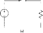 S closed S open (l-D)T FIGURE 13.1 DC chopper with resistive load: (a) circuit diagram; (b) output voltage waveform. where T = 1 is the period of the switching frequency /. The average value of the output vohage is Vo = DVs (13.2) ton + (13.1) and can be regulated by adjusting the duty ratio D. The average output voltage is always smaUer than the input voltage, hence the name of the converter. The dc step-down choppers are commonly used in dc drives. In such a case, the load is represented as a series combination of inductance L, resistance R, and back-emf E as shown in Fig. 13.2a. To provide a path for a continuous inductor current flow when the switch is in the off state, an antiparaUel diode D must be connected across the load. Because the chopper of Fig. 13.2a provides a positive voltage and a positive current to the load, it is caUed a first-quadrant chopper. The load voltage and current are graphed in Fig. 13.2b under assumptions that the load current never reaches zero and the load time constant т = L/R is much greater than the period T. Average values of the output voltage and current can be adjusted by changing the duty ratio D. The dc choppers can also provide peak output voltages higher than the input voltage. Such a step-up configuration is presented in Fig. 13.3. It consists of dc input source V, inductor L connected in series with the source, switch S connecting the inductor to ground, and a series combination of diode D and load. If the switch operates with a duty ratio D, the output voltage is a series of pulses of duration (1 - D)T and amplitude /(1 - D). Therefore, neglecting losses, the average value of the output voltage is V. To obtain an average value of the output voltage greater than V, a capacitor must be connected in paraUel with the load. This results in a topology of a boost dc-dc converter that is described in Section 13.4. 1 ... 18 19 20 21 22 23 24 ... 91 |
|
© 2026 AutoElektrix.ru
Частичное копирование материалов разрешено при условии активной ссылки |