 |
 |
 |
| Главная Журналы Популярное Audi - почему их так назвали? Как появилась марка Bmw? Откуда появился Lexus? Достижения и устремления Mercedes-Benz Первые модели Chevrolet Электромобиль Nissan Leaf |
Главная » Журналы » Metal oxide semiconductor 1 ... 28 29 30 31 32 33 34 ... 91 The control algorithm for the inverter is At +3 = At , + D n+2 (15.28) where D = At +2/W2 - and T = t +4 - t . The schematic of a digital signal processor (DSP)-based controller for the DTC method is shown in Fig. 15.60. The duty cycle can be approximated from the reference sine wave by level shifting and scaling it between 0 and 1. The time W2 ~ is the sum of At +i and At +2- These data provide information for the calculation of the next switching time The switches are triggered by the changing edge of the switch control Q. Approximate delays are added to the individual switching signals for both the inverter switches and the quasi-resonant switches. Typical gating waveforms are shown in Fig. 15.61. The use of the quasi-resonant soft-switched inverter is a very effective way to suppress switching transient and EMI emission. Figure 15.62a,b shows the inverter switch voltage waveforms of a standard hard-switched inverter and a quasi-resonant soft-switched inverter, respectively. It is clear that the soft-switched waveform has much less transient than the hard-switched waveform. 15.14.5 Resonant Pole Inverter and Auxiliary Resonant Commutated Pole Inverter The resonant pole inverter (RPI) integrates the resonant components with the output filter components and Cj The load is connected to the midpoint of the dc bus capacitors as shown in Fig. 15.63. Fiowever, it should be noted that the RPI can be described as a resonant inverter. Figure 15.64 shows 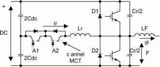 FIGURE 15.67 Improved resonant pole inverter leg. a single-phase RPI. Its operation can be described with the timing diagram in Fig. 15.65. The operating modes are included in Fig. 15.66. The RPI provides soft-switching for aU power switches but it has two disadvantages. First, power devices have to be switched continuously at the resonant frequency determined by the resonant components. Second, the power devices in the RPI circuit require a 2.2 to 2.5 p.u. current turn-off capability. An improved version of the RPI is the auxiliary resonant commutated pole inverter (ARCPI). The ARCPI for one inverter leg is shown in Fig. 15.67. Unlike the basic RPI, the ARCPI aUows the switching frequency to be controUed. Each of the primary switches is closely paraUeled with a snubber capacitor to ensure ZV turn-off. Auxiliary switches are connected in series with an inductor, ensuring that they operate under ZC conditions. For each leg, an auxiliary circuit composed of two extra switches Al and A2, two freewheeling diodes, and a resonant inductor is required. This doubles the number of power switches when compared with hard-switched inverters. Figure 15.68 shows the three-phase ARCPI system. Depending on the load conditions, three commutation modes are generally needed. The commutation methods at low RECTIFIER IN ERTER 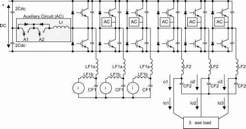 FIGURE 15.68 Three-phase auxiliary resonant commutated pole inverter (ARCPI). and high current are different. This makes the control of the ARCPI very complex. The increase in control and circuit complexity represents a considerable cost penalty [50]. References 1. R.M. Davis, Power Diode and Thyristor Circuits, lEE Monograph, Series 7, 1971. 2. N. Mohan, T. Undeland, and W. Robbins, Power Electronics, Converters, Applications, and Design, New York: John Wiley, 1995. 3. M.H. Rashid, Power Electronics, Circuits, Devices, and Applications, Englewood Cliffs: Prentice Hall, 1993. 4. P. Vinciarelli, Forward Converter Switching at Zero Current, U.S. Patent 4,415,959, Nov. 1983. 5. F.C. Lee, High-Frequency Resonant, Quasi-Resonant and Multi-Resonant Converters, Virginia Power Electronics Center, 1991. 6. F.C. Lee, High-Frequency Resonant and Soft-Switching Converters, Virginia Power Electronics Center, 1991. 7. M.K. Kazimierczuk and D. Czarkowski, Resonant Power Converters, New York: Wiley Interscience, 1995. 8. R.E. Tarter, Solid-State Power Conversion Handbook, New York: Wiley-Interscience 1993. 9. K.H. Liu and F.C. Lee, Resonant Switches - A Unified Approach to Improve Performances of Switching Converters, in Proc. Int Tele-comm. Energy Conf, 1984, pp. 344-351. 10. K.H. Liu, R. Oruganti, and F.C. Lee, Resonant Switches - Topologies and Characteristics, in Proc. IEEE Power Electron. Spec. Conf, 1985, pp. 62-67. 11. K.D.T. Ngo, Generalized of Resonant Switches and Quasi-Resonant DC-DC Converters, in Proc. IEEE Power Electron. Spec. Conf, 1986, pp. 58-70. 12. F.C. Lee, High-frequency Quasi-Resonant and Multi-Resonant Converter Technologies, in Proc. IEEE Int. Conf. Ind. Electron., 1988, pp. 509-521. 13. K.H. Liu and F.C. Lee, Zero-Voltage Switching Techniques in DC/DC Converter Circuits, in Proc. IEEE Power Electron. Spec. Conf, 1986, pp. 58-70. 14. M. Jovanovic, W. Tabisz, and F.C. Lee, Zero-voltage Switching Technique in High Frequency Off-line Converters, in Proc. Applied Power Electron. Conf and Expo., 1988, pp. 23-32. 15. R. Steigerwald, A Comparison of Half-Bridge Resonant Converter Topologies, IEEE Trans. Power Electron, 3:2 174-182, Apr. 1988. 16. O.D. Patterson and D.M. Divan, Pseudo-resonant Full-Bridge DC/DC Converter, in Proc. IEEE Power Electron. Spec. Conf, 1987, pp. 424-430. 17. CP Henze, H.C Martin, and D.W Parsley, Zero-Voltage Switching in High Frequency Power Converters Using Pulse Width Modulation, in Proc. IEEE Applied Power Electron. Conf and Expo., 1988, pp. 33-40. 18. General Electric Company, Full-Bridge Lossless Switching Converters, U.S. Patent 4,864,479, 1989. 19. WA. Tabisz and F.C. Lee, Zero-Voltage-Switching Multi-Resonant Technique - a Novel Approach to Improve Performance of High Frequency Quasi-Resonant Converters, IEEE Trans. Power Electron. 4:4, 450-458, Oct. 1989. 20. WA. Tabisz and F.C. Lee, DC Analysis and Design of Zero-Voltage Switched Multi-Resonant Converters, in Proc. IEEE Power Electron. Spec. Conf, 1989, pp. 243-251. 21. M. Jovanovic and F.C. Lee, DC Analysis of Half-Bridge Zero-Voltage-Switched Multi-Resonant Converter, IEEE Trans. Power Electron. 5:2, 160-171, Apr. 1990. 22. R. Farrington, M.M. Jovanovic, and F.C. Lee, Constant-Frequency Zero-Voltage-Switched Multi-resonant converters: Analysis, Design, and Experimental Results, in Proc. IEEE Power Electron. Spec. Conf, 1990, pp. 197-205. 23. G. Hua, CS. Leu, and F.C. Lee, Novel zero-voltage-transition PWM converters in Proc. IEEE Power Electron. Spec. Conf, 1992, pp. 55-61. 24. R. Watson, G. Hua, and F.C. Lee, Characterization of an Active Clamp Flyback Topology for Power Factor Correction Applications, IEEE Trans. Power Electron. 11:1, 191-198, Jan. 1996. 25. R. Watson, F.C. Lee, and G. Hua, Utilization of an Active-Clamp Circuit to Achieve Soft Switching in Flyback Converters, IEEE Trans. Power Electron. 11:1, 162-169, Jan. 1996. 26. B. Carsten, Design Techniques for Transformer Active Reset Circuits at High Frequency and Power Levels, in Proc. High Freq. Power Conversion Conf, 1990, pp. 235-245. 27. S.D. Johnson, A.F. Witulski, and E. W. Erickson, A Comparison of Resonant Technologies in High Voltage DC Applications, in Proc. lEEEAppli. Power Electron. Conf, 1987, pp. 145-156. 28. A.K.S. Bhat and S.B. Dewan, A Generalized Approach for the Steady State Analysis of Resonant Inverters, IEEE Trans. Ind. Appl. 25:2, 326-338, Mar. 1989. 29. A.K.S. Bhat, A Resonant Converter Suitable for 650V DC Bus Operation, IEEE Trans. Power Eletcron. 6:4, 739-748, Oct. 1991. 30. A.K.S. Bhat and M.M. Swamy, Loss Calculations in Transistorized Parallel Converters Operating Above Resonance, IEEE Trans. Power Electron. 4:4, 449-458, July 1989. 31. A.K.S. Bhat, A Unified Approach for the Steady-State Analysis of Resonant Converter, IEEE Trans. Ind. Electron. 38:4, 251-259, Aug. 1991. 32. Applications Handbook, Unitrode Corporation, 1999. 33. Barbi, J.C Bolacell, D.C Martins, and F.B. Libano, Buck quasi-resonant converter operating at constant frequency: Analysis, design and experimentation, PESC89, pp. 873-880. 34. K.W.E. Cheng and P.D. Evans A family of extended-period circuits for power supply applications using high conversion frequencies, EPE91, pp.4.225-4.230. 35. S.YR. Hui, K.W.E. Cheng, and S.R.N. Prakash, A Mly soft-switched extended-period quasi-resonant power correction circuit, IEEE Trans. Power Electron. 12:5, pp. 922-930, Sept. 1997. 36. H.S.H. Chung and Hui S.Y.R., Reduction of EMI in power converters using fully soft-switching technique, IEEE Trans, on Electromagnetics 40:3, pp. 282-287, August 1998. 37. T. Undeland, Snubbers for pulse width modulated bridge converters with power transistors or GTOs, IPEC, Tokyo, Conference Proceedings, vol.1, pp.313-323, 1983. 38. W. McMurray, Efficient snubbers for voltage source GTO inverters, IEEE Trans, on Power Electron. 2:3, pp.264-272, July 1987. 39. D.M. Divan, The resonant dc link converter - A new concept in static power conversion, IEEE Trans. IA 25:2, 317-325, 1989. 40. Jin-Sheng Lai and К Bose, An induction motor drive using an improved high frequency resonant dc link inverter, IEEE Trans. Power Electron. 6:3, 504-513, 1991. 41. D.M. Divan and G. Skibinski, Zero-switching-loss inverters for high-power applications, IEEE Trans. IA 25:4, 634-643, 1989. 42. S.J. Finney, T.C Green, and B.W Williams, Review of resonant link topologies for inverters, IFF Proc. В 140:2, 103-114, 1993. 43. S.B. Dewan and D.L. Duff, Optimum design of an input commutated inverter for AC motor control, IEEE Trans. Industry Gen. Applications, IGA-5:6, 699-705, Nov/Dec. 1969. 44. V.R. Stefanov and R Bhagwat, A novel dc side commutated inverter, IEEE PESO Record, 1980. 45. A. Kurnia, H. Cherradi and D. Divan, Impact of IGBT behavior on design optimization of soft switching inverter topologies, IEEE IAS Conf. Record, 1993, pp.140-146. 46. Y.C. Jung, J.G. Cho, and G.H. Cho, A new zero voltage switching resonant dc-link inverter with low voltage stress, Proc. IEEE Industrial Electronics Conference, 1991, pp 308-313. 47. S.Y.R. Hui, E.S. Gogani, and J. Zhang, Analysis of a quasi-resonant circuit for soft-switched inverters, IEEE Trans, on Power Electron. 11:1, 106-114, Jan. 1999. 48. D.M. Baker, V.G. Ageliidis, C.W. Meng, and C.V. Nayar, Integrating the digital time control algorithm with DC-bus notching circuit based soft-switching inverter, lEE Proceedings-Electric Power Applications 146:5, 524-529, Sept. 1999. 49. RC. Lee and D. Borojevic, Soft-switching PWM converters and inverters . Tutorial notes, PESC94. 50. D.M. Divan and R.W. De Doncker, Hard and Soft-switching voltage source inverters, Tutorial notes, PESC94. AC-AC Converters Ajit K. Chattopadhyay, Ph.D., Б1ЕЕЕ Electrical Engg. Department Bengal Engineering College (Deemed University) Howrah-711 103 India 16.1 16.2 16.3 16.4 16.5 16.6 Introduction...................................................................................... 307 Single-Phase AC/AC Vohage Controller................................................. 307 16.2.1 Phase-Controlled Single-Phase Alternating Current Voltage Controller 16.2.2 Single-Phase AC/AC Vohage Controller with ON/OFF Control Three-Phase AC/AC Voltage Controllers................................................ 312 16.3.1 Phase-Controlled Three-Phase AC Voltage Controllers 16.3.2 FuUy Controlled Three-Phase Three-Wire AC Voltage Controller Cycloconverters.................................................................................. 316 16.4.1 Single-Phase/Single-Phase Cycloconverter 16.4.2 Three-Phase cycloconverters 16.4.3 Cycloconverter Control Scheme 16.4.4 Cycloconverter Harmonics and Input Current Waveform 16.4.5 Cycloconverter Input Displacement/Power Factor 16.4.6 Effect of Source Impedance 16.4.7 Simulation Analysis of Cycloconverter Performance 16.4.8 Forced-Commutated Cycloconverter (FCC) Matrix Converter................................................................................ 327 16.5.1 Operation and Control Methods of the Matrix Converter 16.5.2 Commutation and Protection Issues in a Matrix Converter Applications of AC/AC Converters........................................................ 331 16.6.1 Applications of AC Voltage Controllers 16.6.2 Applications of Cycloconverters 16.6.3 Apphcations of Matrix Converters References.......................................................................................... 333 16.1 Introduction A power electronic ac/ac converter, in generic form, accepts electric power from one system and converts it for delivery to another ac system with waveforms of different amplitude, frequency, and phase. They may be single-or three-phase types depending on their power ratings. The ac/ac converters employed to vary the rms voltage across the load at constant frequency are known as ac voltage controllers or ac regulators. The voltage control is accomplished either by: (i) phase control under natural commutation using pairs of silicon-controlled rectifiers (SCRs) or triacs; or (ii) by on/off control under forced commutation using fully controUed self-commutated switches such as Gate Turn-off Thyristors (GTOs), power transistors. Insulated Gate Bipolar Transistors (IGBTs), MOS-controUed Thyristors (MCTs), etc. The ac/ac power converters in which ac power at one frequency is directly converted to ac power at another frequency without any intermediate dc conversion link (as in the case of inverters discussed in Chapter 4, Section 14.3) are known as cycloconverters, the majority of which use naturally commutated SCRs for their operation when the maximum output frequency is hmited to a fraction of the input frequency. With the rapid advancement in fast-acting fully controlled switches, force-commutated cycloconverters (FCC) or recently developed matrix converters with bidirectional on/off control switches provide independent control of the magnitude and frequency of the generated output voltage as weU as sinusoidal modulation of output voltage and current. While typical applications of ac voltage controUers include lighting and heating control, on-line transformer tap chaning, soft-starting and speed control of pump and fan drives, the cycloconverters are used mainly for high-power low-speed large ac motor drives for application in cement kilns, roUing miUs, and ship propeUers. The power circuits, control methods, and the operation of the ac voltage controUers, cycloconverters, and matrix converters are introduced in this chapter. A brief review is also given regarding their applications. 16.2 Single-Phase AC/AC Voltage Controller The basic power circuit of a single-phase ac-ac voltage controller, as shown in Fig. 16.1a, is composed of a pair of 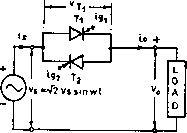 TRWC J V5=V2VsS nwt is H<J 4>h s=>r2Vssinwt 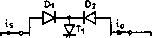 4<HH>H ©Di sinwt FIGURE 16.1 Single-phase ac voltage controllers: (a) full-wave, two SCRs in inverse parallel; (b) full-wave with Triac; (c) full wave with two SCRs and two diodes; (d) full wave with four diodes and one SCR; and (e) half wave with one SCR and one diode in antiparallel. SCRs connected back-to-back (also known as inverse-paraUel or antiparaUel) between the ac supply and the load. This connection provides a bidirectional full-wave symmetrical control and the SCR pair can be replaced by a Triac (Fig. 16.1b) for low-power applications. Alternate arrangements are as shown in Fig. 16.1c with two diodes and two SCRs to provide a common cathode connection for simphfying the gating circuit without needing isolation, and in Fig. 16.Id with one SCR and four diodes to reduce the device cost but with increased device conduction loss. An SCR and diode combination, known as a thyrode controller, as shown in Fig. 16. le, provides a unidirectional half-wave asymmetrical voltage control with device economy but introduces a dc component and more harmonics and thus is not very practical to use except for a very low power heating load. With phase control, the switches conduct the load current for a chosen period of each input cycle of voltage and with on/off control the switches connect the load either for a few cycles of input voltage and disconnect it for the next few cycles (integral cycle control) or the switches are turned on and off several times within alternate half-cycles of input voltage (ac chopper or PWM ac voltage controller). 16.2.1 Phase-Controlled Single-Phase AC Voltage Controller For a fuU-wave, symmetrical phase control, the SCRs and t2 in Fig. 16.1a are gated at a and я + a, respectively, from the zero crossing of the input voltage and by varying a, the power flow to the load is controlled through voltage control in ahernate half-cycles. As long as one SCR is carrying current, the other SCR remains reverse-biased by the voltage drop across the conducting SCR. The principle of operation in each half-cycle is similar to that of the controUed half-wave rectifier (Chapter 11, Section 11.2) and one can use the same approach for analysis of the circuit. 16 AC-AC Converters
The input power factor: P V The average SCR current: 1 a sin 2a 1-- + - л 1/2 (16.3) M,SCR - a/2 V, sin cot d(cDt) (16.4) As each SCR carries half the line current, the rms current in each SCR is   
FIGURE 16.2 Waveforms for single-phase ac full-wave voltage controller with R-load. 4,SCR = I0/V2 (16.5) Operation with RL Load, Figure 16.3 shows the voltage and current waveforms for the controller in Fig. 16.1a with RL load. Due to the inductance, the current carried by the SCR may not faU to zero at cot = n when the input voltage goes negative and may continue until cot = the extinction angle, as shown. The conduction angle (16.6) of the SCR depends on the firing delay angle a and the load impedance angle ф. The expression for the load current Io(cot) Operation with R-load, Figure 16.2 shows the typical voltage and current waveforms for the single-phase bidirectional phase-controlled ac voltage controUer of Fig. 16.1a with resistive load. The output voltage and current waveforms have half-wave symmetry and thus no dc component. If i; = a/2 sin cot is the source voltage, then the rms output voltage with triggered at a can be found from the half-wave symmetry as IVsin cot d(cDt)
(16.1) Note that can be varied from to 0 by varying a from 0 to 71. The rms value of load current: R 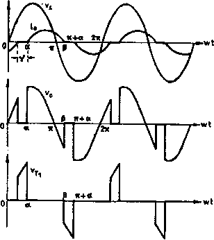 (16 2) FIGURE 16.3 Typical waveforms of single-phase ac voltage controller with an i?L-load. when conducting from a to can be derived in the same way as that used for a phase-controUed rectifier in a discontinuous mode (Chaper 11, Section 11.2) by solving the relevant Kirchhoff voltage equation: а/2У /(cot) = [sin(ajt - Ф)- sin(a - a-cot)/ tanj a<(Dt <P (16.7) where Z = {P} + coL) = load impedance and ф = load impedance angle = tan~(coL/i). The angle , when the current faUs to zero, can be determined from the foUowing transcendental equation obtained by putting iicot = ) = 0 in Eq. (16.7) sm{P -ф) = sin(a -Ф)- sin(a - (/))e(->/ (16.8) From Eqs. (16.6) and (16.8) one can obtain a relationship between в and a for a given value of ф as shown in Fig. 16.4, which shows that as a is increased the conduction angle в decreases and the rms value of the current decreases. The rms output voltage nl/2 IVsincDt d(t) sin 2a sin 2 nl/2 can be evaluated for two possible extreme values of ф = 0 when P = n and ф = n/2 when = 2я - a, and the envelope of the voltage-control characteristics for this controUer is shown in Fig. 16.5. <D 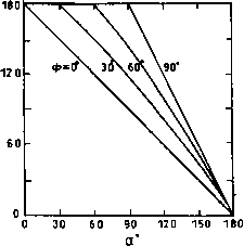 FIGURE 16.4 в vs a curves for single-phase ac voltage controller with RL load. 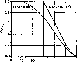 90 120 150 160 Firing Angle (Cl FIGURE 16.5 Envelope of control characteristics of a single-phase ac voltage controller with RL load. The rms SCR current can be obtained from Eq. (16.7) as ,SCR - i] d(cot) (16.10) The rms load current (16.9) average value of SCR current 4, SCR - i, d(CDt) (16.11) (16.12) Gating Signal Requirements, For the inverse parallel SCRs as shown in Fig. 16.1a, the gating signals of SCRs must be isolated from one another as there is no common cathode. For i-load, each SCR stops conducting at the end of each half-cycle and under this condition, single short pulses may be used for gating as shown in Fig. 16.2. With RL load, however, this single short pulse gating is not suitable as shown in Fig. 16.6. When SCR T2 is triggered at cot = я + a, SCR is stiU conducting due to the load inductance. By the time the SCR Tl stops conducting at , the gate pulse for SCR T2 has already ceased and T2 wiU faU to turn on, causing the converter to operate as a single-phase rectifier with conduction of only. This necessitates apphcation of a sustained gate pulse either in the form of a continuous signal for the half-cycle period, which increases the dissipation in SCR gate circuit and a large isolating pluse transformer or better a train of pulses (carrier frequency gating) to overcome these difficulties. Operation with a < ф. If a = then from Eq. (16.8), sm(l] -ф) = sm(l] - a) = 0 (16.13) 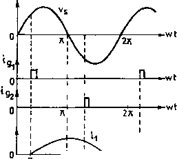 -I I-3.-1 > Wt 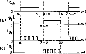 FIGURE 16.6 Single-phase full-wave controller with RL load: Gate pulse requirements. (16.14) As the conduction angle в cannot exceed % and the load current must pass through zero, the control range of the firing angle is ф < a < n. With narrow gating pulses and a < ф, only one SCR wiU conduct resulting in a rectifier action as shown. Even with a train of pulses, if a < ф, the changes in the firing angle wiU not change the output voltage and current but both SCRs wiU conduct for the period n with becoming on at cot = n and T2 at cot + n. This dead zone (a = 0 to ф), whose duration varies with the load impedance angle ф, is not a desirable feature in closed-loop control schemes. An alternative approach to the phase control with respect to the input voltage zero crossing has been reported in which the firing angle is defined with respect to the instant when it is the load current (not the input voltage) that reaches zero, this angle being called the hold-off angle (y) or the control angle (as marked in Fig. 16.3). This method requires sensing the load current - which may otherwise be required anyway in a closed-loop controller for monitoring or control purposes. I 0Л e < I 0.4
firing anle a* FIGURE 16.7 Harmonic content as a function of the firing angle for a single-phase voltage controller with RL load. Power Factor and Harmonics, As in the case of phase-controlled rectifiers, the important limitations of the phase-controlled ac voltage controllers are the poor power factor and the introduction of harmonics in the source currents. As seen from Eq. (16.3), the input power factor depends on a, and as a increases, the power factor decreases. The harmonic distortion increases and the quality of the input current decreases with increase of firing angle. The variations of low-order harmonics with the firing angle as computed by Fourier analysis of the voltage waveform of Fig. 16.2 (with i-load) are shown in Fig. 16.7. Only odd harmonics exist in the input current because of half-wave symmetry. 16.2.2 Single-Phase AC/AC Vohage Controller with ON/OFF Control Integral Cycle Control, As an alternative to the phase control, the method of integral cycle control or burst-firing is used for heating loads. Fiere, the switch is turned on for a time t with n integral cycles and turned off for a time t with m integral cycles (Fig. 16.8). As the SCRs or Triacs used here are turned on at the zero-crossing of the input voltage and turn-off occurs at zero current, supply harmonics and radio frequency interference are very low. Fiowever, subharmonic frequency components may be generated that are undesirable as they may set up subharmonic resonance in the power supply system, cause lamp flicker, and 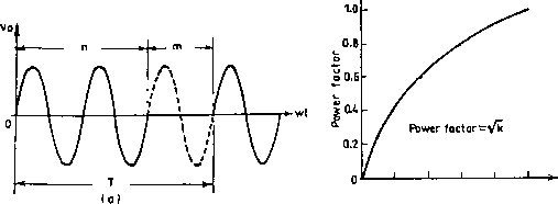 0.2 V* 0.6 ав 1.0 FIGURE 16.8 Integral cycle control: (a) typical load-voltage waveforms; and (b) power factor with the duty cycle k. may interfere with the natural frequencies of motor loads causing shaft oscillations. For sinusoidal input voltage v = a/2 sin cot, the rms output voltage (16.15) where к = nl{n -\- m) = duty cycle and = rms phase voltage. The power factor is which is poorer for lower values of the duty cycle k. (16.16) PWM AC Chopper, As in the case of controUed rectifier in Chapter 11, Section 11.6, the performance of ac voltage controllers can be improved in terms of harmonics, quality of output current and input power factor by pulsewidth modulation (PWM) control in PWM ac choppers. The circuit configuration of one such single-phase unit is shown in Fig. 16.9. Here, fully controUed switches Si and s2 connected in antiparaUel are turned on and off many times during the positive and negative half-cycles of the input voltage, respectively; S[ and 82 provide the freewheeling paths for the load current when Si and s2 are off. An input capacitor filter 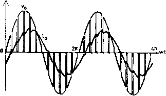 FIGURE 16.10 Typical output voltage and current waveforms of a single-phase PWM ac chopper. may be provided to attenuate the high switching frequency current drawn from the supply and also to improve the input power factor. Figure 16.10 shows the typical output voltage and load-current waveform for a single-phase PWM ac chopper. It can be shown that the control characteristics of an ac chopper depend on the modulation index M, which theoretically varies from zero to unity. Three-phase PWM choppers consist of three single-phase choppers either delta connected or four-wire star connected. FIGURE 16.9 Single-phase PWM as chopper circuit. 16.3 Three-Phase AC/AC Voltage Controllers 16.3.1 Phase-Controlled Three-Phase AC Voltage Controllers Various Configurations, Several possible circuit configurations for three-phase phase-controUed ac regulators with star-or delta-connected loads are shown in Fig. 16.1 la-h. The configurations in Fig. 16.11a and b can be realized by three single-phase ac regulators operating independently of each other and they are easy to analyze. In Fig. 16.11a, the SCRs are 1 ... 28 29 30 31 32 33 34 ... 91 |
||||||||||||||||||||||||||||||||||||||||||||||||||||||||||||||||||||||||||||||||||||||||||||||||||||||||||||||||||||||||||||||||
|
© 2026 AutoElektrix.ru
Частичное копирование материалов разрешено при условии активной ссылки |